ProSoft inRAx MVI71-GSC User manual

MVI71-GSC
PLC Platform
Generic Serial Communication Module
User Manual
January 31, 2008

Please Read This Notice
Successful application of this module requires a reasonable working knowledge of the Rockwell
Automation PLC hardware, the MVI71-GSC Module and the application in which the combination is
to be used. For this reason, it is important that those responsible for implementation satisfy
themselves that the combination will meet the needs of the application without exposing personnel
or equipment to unsafe or inappropriate working conditions.
This manual is provided to assist the user. Every attempt has been made to ensure that the
information provided is accurate and a true reflection of the product's installation requirements. In
order to ensure a complete understanding of the operation of the product, the user should read all
applicable Rockwell Automation documentation on the operation of the Rockwell Automation
hardware.
Under no conditions will ProSoft Technology be responsible or liable for indirect or consequential
damages resulting from the use or application of the product.
Reproduction of the contents of this manual, in whole or in part, without written permission from
ProSoft Technology is prohibited.
Information in this manual is subject to change without notice and does not represent a
commitment on the part of ProSoft Technology Improvements and/or changes in this manual or the
product may be made at any time. These changes will be made periodically to correct technical
inaccuracies or typographical errors.
Warning: This module is not hot-swappable! Always remove power from the rack before
inserting or removing this module, or damage may result to the module, the processor, or other
connected devices.
Power, Input, and Output (I/O) wiring must be in accordance with Class 1,
Division 2 wiring methods, Article 501-4 (b) of the National Electrical Code, NFPA
70 for installation in the U.S., or as specified in Section 18-1J2 of the Canadian
Electrical Code for installations in Canada, and in accordance with the authority
having jurisdiction.
A Warning - Explosion Hazard - Substitution of components may impair
suitability for Class 1, Division 2.
B Warning - Explosion Hazard - When in hazardous locations, turn off power
before replacing or wiring modules.
C Warning - Explosion Hazard - Do not disconnect equipment unless power has
been switched off or the area is known to be non-hazardous.

Your Feedback Please
We always want you to feel that you made the right decision to use our products. If you have
suggestions, comments, compliments or complaints about the product, documentation or support,
please write or call us.
ProSoft Technology
1675 Chester Avenue, Fourth Floor
Bakersfield, CA 93301
+1 (661) 716-5100
+1 (661) 716-5101 (Fax)
http://www.prosoft-technology.com
Copyright © ProSoft Technology, Inc. 2000 - 2008. All Rights Reserved.
MVI71-GSC User Manual
January 31, 2008
PSFT..MVI71.UM.08.01.31
ProSoft Technology ®, ProLinx ®, inRAx ®, ProTalk® and RadioLinx ® are Registered Trademarks
of ProSoft Technology, Inc.


Contents MVI71-GSC ♦PLC Platform
Generic Serial Communication Module
ProSoft Technology, Inc. Page 5 of 82
January 31, 2008
Contents
PLEASE READ THIS NOTICE................................................................................................................2
Your Feedback Please ......................................................................................................................3
GUIDE TO THE MVI71-GSC USER MANUAL .......................................................................................7
1START HERE....................................................................................................................................9
1.1 System Requirements.................................................................................................................9
1.2 Package Contents.....................................................................................................................10
1.3 Setting Jumpers ........................................................................................................................11
1.4 Install the Module in the Rack...................................................................................................11
1.5 Connect your PC to the Processor ...........................................................................................13
1.6 Download the Sample Program to the Processor.....................................................................14
1.1.1 Configuring RSLinx.................................................................................................................... 15
1.7 Connect your PC to the Module................................................................................................17
2INSTALLING AND CONFIGURING THE MODULE.......................................................................19
1.8 Module Configuration................................................................................................................20
2.1.1 Power Up................................................................................................................................... 21
1.9 Module Data Files .....................................................................................................................21
2.1.2 Configuration Data..................................................................................................................... 21
2.1.3 Status Data................................................................................................................................ 25
2.1.4 MVI71-GSC Status Data Definition............................................................................................ 26
3LADDER LOGIC .............................................................................................................................31
4DIAGNOSTICS AND TROUBLESHOOTING.................................................................................33
1.10 Reading Status Data from the module ...............................................................................33
4.1.1 The Configuration/Debug Menu................................................................................................. 33
4.1.2 Required Hardware ................................................................................................................... 34
4.1.3 Required Software..................................................................................................................... 34
4.1.4 Using the Configuration/Debug Port .......................................................................................... 35
4.1.5 Main Menu................................................................................................................................. 36
4.1.6 Data Analyzer............................................................................................................................ 38
4.1.7 Data Analyzer Tips .................................................................................................................... 41
1.11 LED Status Indicators.........................................................................................................43
1.12 Clearing a Fault Condition..................................................................................................44
1.13 Troubleshooting..................................................................................................................44
5REFERENCE...................................................................................................................................45
1.14 Product Specifications ........................................................................................................45
5.1.1 Features and Benefits ............................................................................................................... 45
5.1.2 General Specifications............................................................................................................... 45
5.1.3 Hardware Specifications............................................................................................................ 45
5.1.4 Functional Specifications........................................................................................................... 46
1.15 Functional Overview ...........................................................................................................47
5.1.5 General Concepts...................................................................................................................... 47
5.1.6 Backplane Data Transfer........................................................................................................... 48
5.1.7 Normal Data Transfer ................................................................................................................ 50
5.1.8 Configuration Data Transfer ...................................................................................................... 57
5.1.9 Command Control Blocks..........................................................................................................58
5.1.10 Data Flow between MVI71-GSC Module and PLC Processor................................................... 59
5.1.11 Termination of Received Data ................................................................................................... 61
1.16 Cable Connections .............................................................................................................63
5.1.12 RS-232 Configuration/Debug Port............................................................................................. 64
5.1.13 RS-232 ...................................................................................................................................... 66
5.1.14 RS-422 ...................................................................................................................................... 68

MVI71-GSC ♦PLC Platform Contents
Generic Serial Communication Module
Page 6 of 82
January 31, 2008
5.1.15 RS-485 ...................................................................................................................................... 68
5.1.16 DB9 to RJ45 Adaptor (Cable 14)............................................................................................... 69
6SUPPORT, SERVICE & WARRANTY........................................................................................... 71
6.1 How to Contact Us: Sales and Support.................................................................................... 72
6.2 Return Material Authorization (RMA) Policies and Conditions................................................. 73
6.2.1 All Product Returns ................................................................................................................... 73
1.17 Procedures for Return of Units Under Warranty................................................................ 73
1.18 Procedures for Return of Units Out of Warranty................................................................ 74
6.2.2 Un-repairable Units ................................................................................................................... 74
6.2.3 Purchasing Warranty Extension ................................................................................................ 75
1.19 LIMITED WARRANTY ....................................................................................................... 75
6.2.4 What Is Covered By This Warranty ........................................................................................... 75
6.2.5 What Is Not Covered By This Warranty..................................................................................... 76
6.2.6 DISCLAIMER REGARDING HIGH RISK ACTIVITIES .............................................................. 77
6.2.7 DISCLAIMER OF ALL OTHER WARRANTIES......................................................................... 77
6.2.8 LIMITATION OF REMEDIES**.................................................................................................. 77
6.2.9 Time Limit for Bringing Suit ....................................................................................................... 77
6.2.10 No Other Warranties ................................................................................................................. 78
6.2.11 Intellectual Property................................................................................................................... 78
6.2.12 Additional Restrictions Relating To Software And Other Intellectual Property........................... 78
6.2.13 Allocation of risks ...................................................................................................................... 78
6.2.14 Controlling Law and Severability ............................................................................................... 79
INDEX.................................................................................................................................................... 81

Start Here MVI71-GSC ♦PLC Platform
Generic Serial Communication Module
ProSoft Technology, Inc. Page 7 of 82
January 31, 2008
Guide to the MVI71-GSC User Manual
Function Section to Read Details
Introduction
(Must Do)
→
Start Here (page
19, page 9)
This Section introduces the customer to the
module. Included are: package contents,
system requirements, hardware installation,
and basic configuration.
Verify Communication,
Diagnostic and
Troubleshooting
→Verifying
Communication
(page 33)
Diagnostics and
Troubleshooting
(page 33)
This section describes how to verify
communications with the network. Diagnostic
and Troubleshooting procedures.
Reference
Product Specifications
Functional Overview
Glossary
→Reference (page
45)
Functional
Overview (page 47)
Product
Specifications
(page 45)
These sections contain general references
associated with this product, Specifications,
and the Functional Overview.
Support, Service, and
Warranty
Index
→Support, Service
and Warranty
(page 71)
This section contains Support, Service and
Warranty information.
Index of chapters.

MVI71-GSC ♦PLC Platform Start Here
Generic Serial Communication Module
Page 8 of 82 ProSoft Technology, Inc.
January 31, 2008
Start Here MVI71-GSC ♦PLC Platform
Generic Serial Communication Module
ProSoft Technology, Inc. Page 9 of 82
January 31, 2008
1 Start Here
In This Chapter
System Requirements .............................................................................9
Package Contents .................................................................................10
Setting Jumpers ....................................................................................11
Install the Module in the Rack ...............................................................11
Connect your PC to the Processor ........................................................13
Download the Sample Program to the Processor..................................14
Connect your PC to the Module ............................................................17
Installing the MVI71-GSC module requires a reasonable working knowledge of
the Rockwell Automation hardware, the MVI71-GSC Module and the application
in which they will be used.
Caution: It is important that those responsible for implementation can complete the
application without exposing personnel, or equipment, to unsafe or inappropriate working
conditions. Safety, quality and experience are key factors in a successful installation.
1.1 System Requirements
The MVI71-GSC module requires the following minimum hardware and software
components:
Rockwell Automation PLC processor, with compatible power supply and one
free slot in the rack, for the MVI71-GSC module. The module requires 800mA
of available power.
The PLC Processor must provide for at least 64 words of BTR/BTW area,
otherwise the module may not function correctly.
Rockwell Automation RSLogix 5 programming software.
Rockwell Automation RSLinx communication software
Pentium® 100 MHz minimum. Pentium III 700 MHz (or better) recommended
Supported operating systems:
oMicrosoft Windows XP
oMicrosoft Windows 2000
oMicrosoft Windows NT v4.0 with Service Pack 3 or greater
oMicrosoft Windows ME
oMicrosoft Windows 98
64 Mbytes of RAM minimum, 256 Mbytes of RAM recommended

MVI71-GSC ♦PLC Platform Start Here
Generic Serial Communication Module
Page 10 of 82 ProSoft Technology, Inc.
January 31, 2008
100 Mbytes of free hard disk space (or more based on application
requirements)
256-color VGA graphics adapter, 800 x 600 minimum resolution (True Color
1024 ×768 recommended)
CD-ROM drive
3.5 inch floppy disk drive
HyperTerminal or other terminal emulator program capable of file transfers
using Ymodem protocol.
1.2 Package Contents
The following components are included with your MVI71-GSC module, and are
all required for installation and configuration.
Important: Before beginning the installation, please verify that all of the following items are
present.
Qty. Part Name Part Number Part Description
1 MVI71-GSC
Module
MVI71-GSC Generic Serial Communication Module
1 Cable RS232 Null
Modem
For RS232 Connection to the CFG Port
3 Cable Cable #14, RJ45 to
DB9 Male Adapter
For DB9 Connection to Module's Port
2 Adapter 1454-9F Two Adapters, DB9 Female to Screw Terminal.
For RS422 or RS485 Connections to Port 1 and 2
of the Module
1 ProSoft
Solutions
CD
Contains sample programs, utilities and
documentation for the MVI71-GSC module.
If any of these components are missing, please contact ProSoft Technology
Support for replacement parts.
Start Here MVI71-GSC ♦PLC Platform
Generic Serial Communication Module
ProSoft Technology, Inc. Page 11 of 82
January 31, 2008
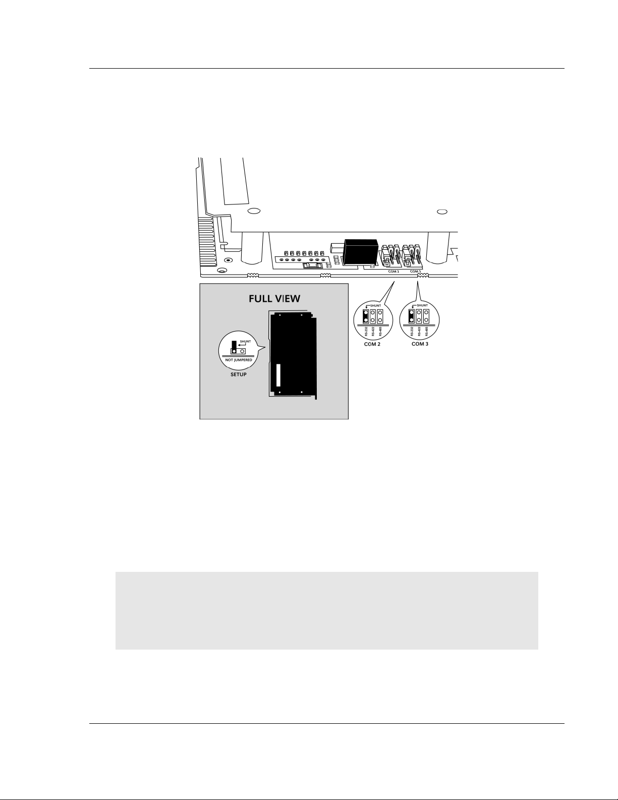
1.3 Setting Jumpers
The following illustration shows the jumper configurations for the various RS
interfaces. If you are using an interface other than RS-232 (default), you must
change the jumpers as shown:
The Setup Jumper acts as "write protection" for the module's flash memory. In
"write protected" mode, the Setup pins are not connected, and the module's
firmware cannot be overwritten. Do not jumper the Setup pins together unless
you are directed to do so by ProSoft Technical Support.
1.4 Install the Module in the Rack
If you have not already installed and configured your PLC processor and power
supply, please do so before installing the MVI71-GSC module. Refer to your
Rockwell Automation product documentation for installation instructions.
Warning: You must follow all safety instructions when installing this or any other electronic
devices. Failure to follow safety procedures could result in damage to hardware or data, or even
serious injury or death to personnel. Refer to the documentation for each device you plan to
connect to verify that suitable safety procedures are in place before installing or servicing the
device.
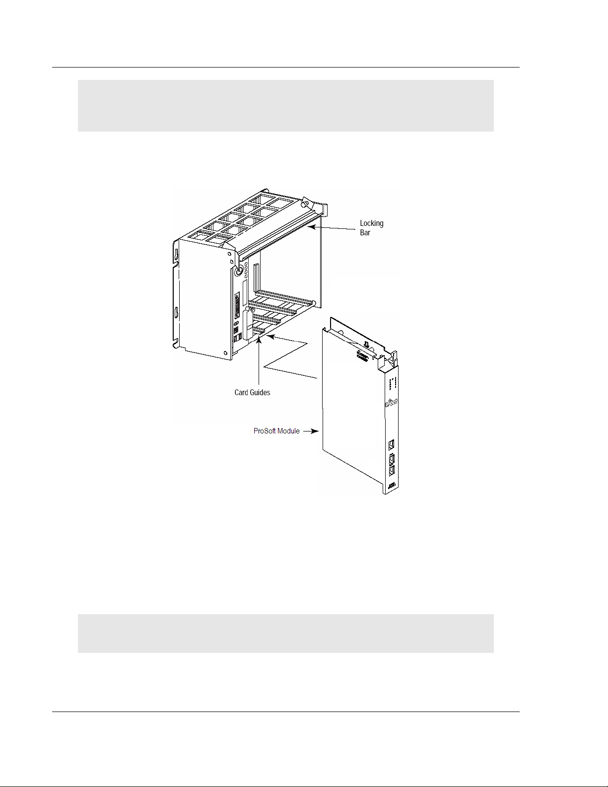
After you have checked the placement of the jumpers, insert MVI71-GSC into the
PLC™ chassis. Use the same technique recommended by Rockwell Automation
to remove and install PLC modules.
MVI71-GSC ♦PLC Platform Start Here
Generic Serial Communication Module
Page 12 of 82 ProSoft Technology, Inc.
January 31, 2008
Warning: This module is not hot-swappable! Always remove power from the rack before
inserting or removing this module, or damage may result to the module, the processor, or other
connected devices.
1 Turn power OFF.
2 Align the module with the top and bottom guides, and slide it into the rack
until the module is firmly against the backplane connector.
3 With a firm but steady push, snap the module into place.
4 Check that the holding clips on the top and bottom of the module are securely
in the locking holes of the rack.
5 Make a note of the slot location. You will need to identify the slot in which the
module is installed in order for the sample program to work correctly. Slot
numbers are identified on the green circuit board (backplane) of the PLC
rack.
6 Turn power ON.
Note: If you insert the module improperly, the system may stop working, or may behave
unpredictably.

Start Here MVI71-GSC ♦PLC Platform
Generic Serial Communication Module
ProSoft Technology, Inc. Page 13 of 82
January 31, 2008
1.5 Connect your PC to the Processor
1 Connect the right-angle connector end of the cable to your controller at the
communications port.
2 Connect the straight connector end of the cable to the serial port on your
computer.
MVI71-GSC ♦PLC Platform Start Here
Generic Serial Communication Module
Page 14 of 82 ProSoft Technology, Inc.
January 31, 2008
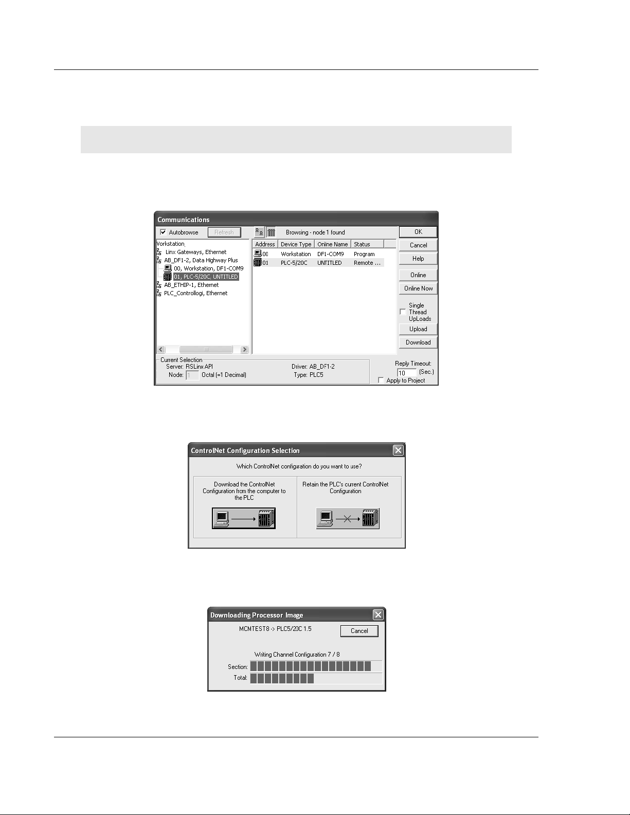
1.6 Download the Sample Program to the Processor
To download the sample program from RSLogix 5 to the PLC processor:
Note: The key switch on the front of the PLC processor must be in the REM position.
1 If you are not already online to the processor, open the Communications
menu, and then choose Download. RSLogix will establish communication
with the processor.
2 Click the Download button to transfer the sample program to the processor.
3 When prompted, choose Computer to PLC
4 RSLogix will compile the program and transfer it to the processor. This
process may take a few minutes.

Start Here MVI71-GSC ♦PLC Platform
Generic Serial Communication Module
ProSoft Technology, Inc. Page 15 of 82
January 31, 2008
5 When the download is complete, RSLogix will open another confirmation
dialog box. Click OK to switch the processor from Program mode to Run
mode.
Note: If you receive an error message during these steps, refer to your RSLogix documentation to
interpret and correct the error.
1.1.1 Configuring RSLinx
If RSLogix is unable to establish communication with the processor, follow
these steps:
1 Open RSLinx.
2 Open the Communications menu, and choose Configure Drivers.
This action opens the Configure Drivers dialog box.
Note: If the list of configured drivers is blank, you must first choose and configure a driver from the
Available Driver Types list. The recommended driver type to choose for serial communication with
the processor is "RS-232 DF1 Devices".

MVI71-GSC ♦PLC Platform Start Here
Generic Serial Communication Module
Page 16 of 82 ProSoft Technology, Inc.
January 31, 2008
3 Click to select the driver, and then click Configure. This action opens the
Configure Allen-Bradley DF1 Communications Device dialog box.
4 Click the Auto-Configure button. RSLinx will attempt to configure your serial
port to work with the selected driver.
5 When you see the message "Auto Configuration Successful", click the OK
button to dismiss the dialog box.
Note: If the auto-configuration procedure fails, verify that the cables are connected correctly
between the processor and the serial port on your computer, and then try again. If you are still
unable to auto-configure the port, refer to your RSLinx documentation for further troubleshooting
steps.

Start Here MVI71-GSC ♦PLC Platform
Generic Serial Communication Module
ProSoft Technology, Inc. Page 17 of 82
January 31, 2008
1.7 Connect your PC to the Module
With the module securely mounted, connect your PC to the Configuration/Debug
port using an RJ45-DB-9 Serial Adapter Cable and a Null Modem Cable.
1 Attach both cables as shown.
2 Insert the RJ45 cable connector into the Configuration/Debug port of the
module.
3 Attach the other end to the serial port on your PC or laptop.

MVI71-GSC ♦PLC Platform Start Here
Generic Serial Communication Module
Page 18 of 82 ProSoft Technology, Inc.
January 31, 2008

Installing and Configuring the Module MVI71-GSC ♦PLC Platform
Generic Serial Communication Module
ProSoft Technology, Inc. Page 19 of 82
January 31, 2008
2 Installing and Configuring the Module
In This Chapter
Module Configuration ............................................................................20
Module Data Files .................................................................................21
This chapter describes how to install and configure the module to work with your
application. The configuration process consists of the following steps.
1 Use RSLogix 5 to identify the module to the processor and add the module to
a project.
Note: The RSLogix 5 software must be in "offline" mode to add the module to a project.
2 Modify the example ladder logic to meet the needs of your application, and
copy the ladder logic to the processor. Example ladder logic files are provided
on the CD-ROM.
Note: If you are installing this module in an existing application, you can copy the necessary
elements from the example ladder logic into your application.
The rest of this chapter describes these steps in more detail.
The first step in installing and configuring the module is to define whether the
block transfer or side-connect interface will be utilized. If the block transfer
interface is to be used, remove the Compact Flash Disk from the module if it is
present and insert the module into the rack with the power turned off.
If the side-connect interface is utilized, make sure the file SC_DATA.TXT on the
Compact Flash Disk contains the correct configuration file number. You can run
the setdnpsc.exe program to set the configuration file number to be used with
your application. Install the module in the rack and turn on the power. Connect
the terminal server to the module's debug/configuration port and exit the program
by pressing the Esc key followed by the 'X' key. This will cause the program to
exit and remain at the operating system prompt. Run the setdnpsc.exe program
with a command line argument of the file number to use for the configuration file.
For example, to select N10: as the configuration file, enter the following:
SETDNPSC 10
The program will build the SC_DATA.TXT on the Compact Flash Disk (C: drive in
the root directory).
The next step in module setup is to define the data files to be used with the
application. If the block transfer interface is used, define the data files to hold the
configuration, status and user data. Enter the module's configuration in the user
data files. Enter the ladder logic to handle the blocks transferred between the
module and the PLC. Download the program to the PLC and test the program
with the module.

MVI71-GSC ♦PLC Platform Installing and Configuring the Module
Generic Serial Communication Module
Page 20 of 82 ProSoft Technology, Inc.
January 31, 2008
If the side-connect interface is used, minimum ladder logic is required for data
transfer. The user data files to interface with the module must reside in
contiguous order in the processor. The first file to be used by the interface is the
configuration file. This is file number set in the SC_DATA.TXT file using the
SETDNPSC.EXE program. The following table lists the files used by the side-
connect interface:
File Number Example Size Description
Cfg File N10 300 Configuration/Control/Status File
Cfg File+1 N11 500 Data transferred from the module to the processor
Cfg File+2 N12 500 Data transferred from the processor to the module
Even if the files are not required for an application, they still are reserved and
should only be used for that purpose. The read and write data contained in the
last set of files possess the data transferred between the module and the
processor. The read data file (Cfg File + 1) will contain data received on the
communication port and passed to the module. The write data file (Cfg File + 2)
will contain data passed to the module from the processor to be sent out the
communication ports.
Special care must be taken when defining the files for the side-connect interface.
Because the module directly interacts with the PLC processor and its memory,
any errors in the configuration may cause the processor to fault and it may even
lose its configuration and program. After defining the files and populating them
with the correct data, download the program to the processor, and place the
processor in run mode. If everything is configured correctly, the module should
start its normal operation.
If all the configuration parameters are set correctly and the module is attached to
a network, the module's Application LED (APP LED) should remain off and the
backplane activity LED (BP ACT) should blink very rapidly. Refer to the
Troubleshooting section if you encounter errors. Attach a computer or terminal
to Port 0 on the module and look at the status of the module using the
Configuration/Debug Menu in the module. Refer to the Configuration/Debug
Port section for a complete discussion of the use of this feature.
1.8 Module Configuration
In order for the MVI71-GSC module to function, a minimum amount of
configuration data must be transferred to the module. The following table
provides an overview of the different types of configuration data that the module
will require, depending on the operating modes to be supported.
Function Name Description
Data
Transfer
General Module
Configuration
This section of the configuration data contains the
module configuration data that defines the data
transfer between the module and the PLC processor.
Serial Port
Drivers
Port Configuration These sections define the characteristics of each of
the serial communication ports on the module. These
parameters must be set correctly for proper module
operation.
Table of contents
Other ProSoft Conference System manuals


