WolfPack HDTVHRS5500 User manual

1
ALL-IN-ONE Huddle Room Solution
Version: V1.0.1
USER MANUAL
HDTVHRS5500

2
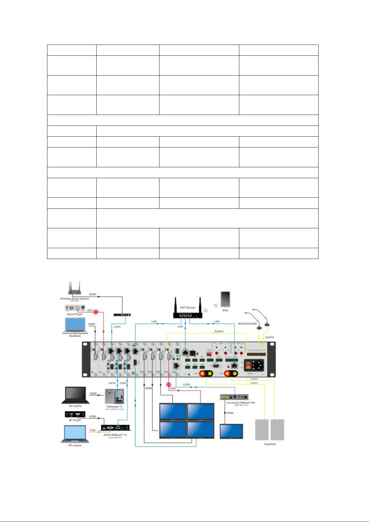
1. Product description:
medium sized conference rooms. It integrates a 5x5 hybrid/modular matrix switcher, an 8x4 audio
processor, 2*150W amplifier system and a central control system in a 2RU chassis. With the highly
integration and good compatibility to provide users a friendly and easy use for the conference
room, truly realized the function of BYOD.
other video signal input and output. Support optical signal input and output,transmission distance
up to 10 km over a single optical fiber. Support HDBaseT network cable signal input and output, the
transmission distance up to 100 meters over a single network cable. Support seamless switching,
resolution conversion, and a variety of fixed resolution output.
processing bus architecture, fixed I/O structure, faster TI L138 FLOPS DSP chip controlling and
processing audio streams, intuitively present the software design of sound from input -
amplification - noise reduction - mixing - noise reduction - Output the entire process. The operation
interface is simple and concise. The control software includes grouping control, parameter copying,
pasting and joint control functions. According to the acoustic characteristics of different functions,
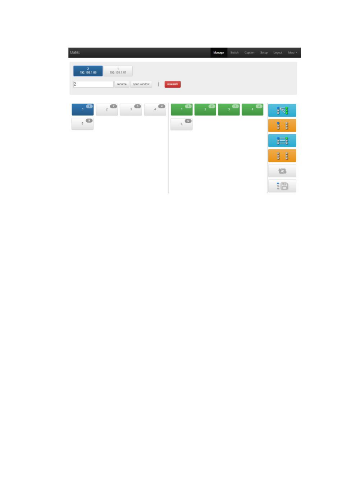
editing and storage of scene (conference mode, performance mode and singing mode). B/S
architecture client enabling control by mobile phone, tablet, laptop and other movable terminals. It
also integrates two 150W digital power amplifier module enabling drives the speakers directly.
The central controller configuration up to 4000MHz 32-bit embedded processor, built-in 32M
memory and 4M memory FLASH, enabling high speed operation of complex logic instructions; open
programmable control platform, user-friendly Chinese operation Interface and interactive control
structure; built-in infrared learning function, enabling users to create its own infrared code
database and one-key dual-code infrared logic control; extended Ethernet control interface
enabling computer remote control; muti-connection Ethernet interface enabling easy to connect
IPAD and Android touch screen.
The applications from the meeting rooms, function rooms, theaters, concert halls, classrooms,
exhibitions, public transport centers, stadiums, churches, and other applications demands.
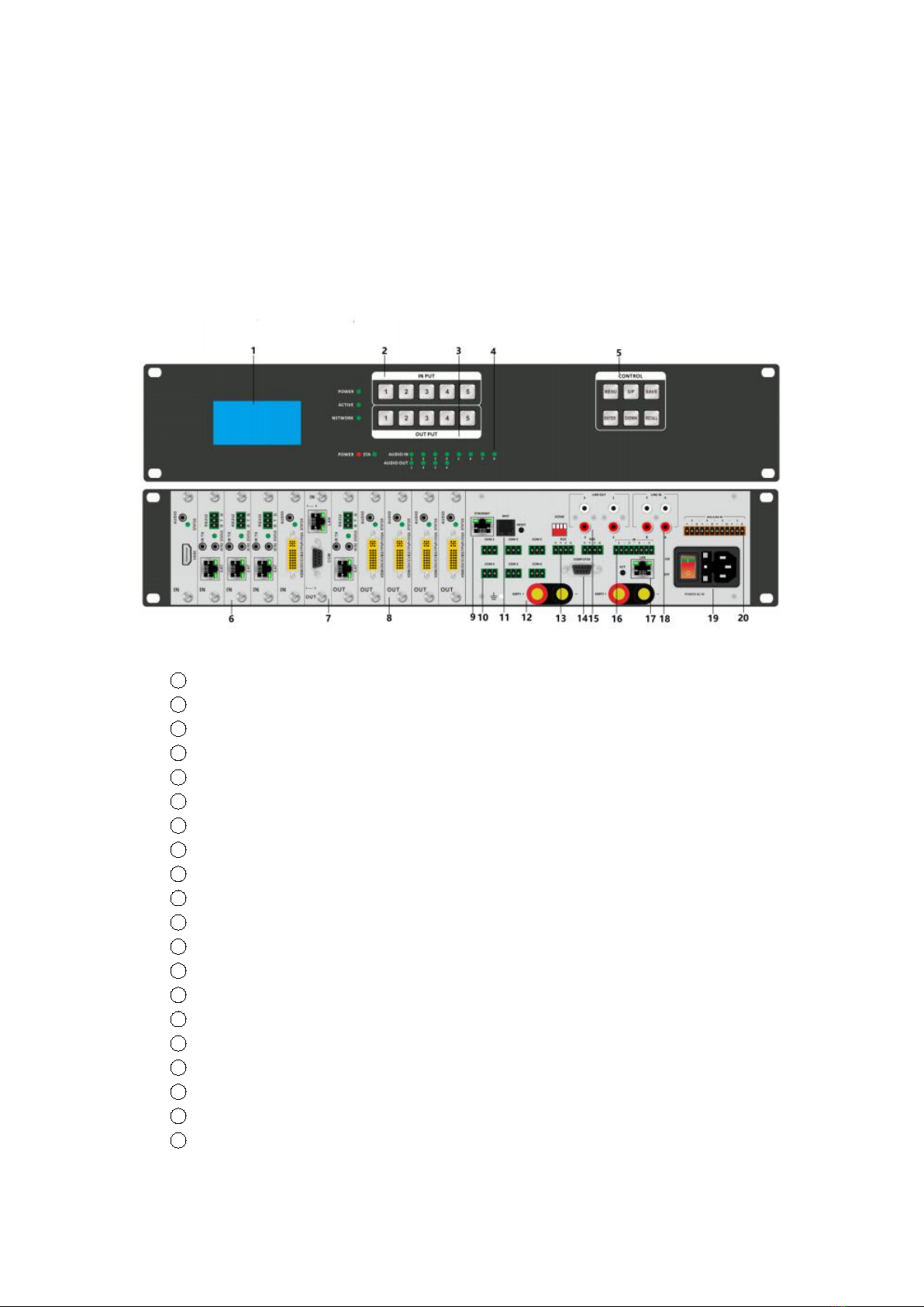
2. Product Features:
Video section
Card cage and 1 card 1 port designing,there are 5 input slots and 5 output slots.
Support 3GSDI, DVI, HDMI, analog signal, optical signal, network cable signal input, adaptive input.
Support 3GSDI, DVI, HDMI, analog signals, optical signals, network cable signal output
Support seamless switching, no black,no blue,no crack screen when switching
Support Fiber input and output, the transmission distance up to 10 km over a single optical fiber
Support HDBaseT input and output,transmission 70 meters or 100 meters over a single Cat
Front control buttons with background light
Support RS232/WEB GUI/ APP control
Audio section
HDTVHRS5500 is aAll-in-one Huddle RoomSolution product, it’sspecially developed forsmall and
HDTVHRS5500 supports 3GSDI,DVI,HDMI,analogsignals, optical signals, networkcable signals and
The HDTVHRS5500 usesthird-generationaudioprocessing technology. High quality amplifier,DSP

3
Support 4 balanced / unbalanced analog channel input and 4 unbalanced analog channel input
Support 4 unbalanced analog channel output
Support 2 * 150W digital power amplifier
Texas Instruments TI core processing chip(450MHz Flops)
Sampling standard 48KHz / 24bit (up to 192KHz / 32bit) High-quality A / D and D / A converter
Support Windows, Android, iOS three platform client
DSP audio processing, built-in automatic mixer, feedback cancellation, echo cancellation, noise
cancellation module
Input: pre-amplification, signal generator, expander, compressor, 5-band parametric equalizer,
automatic gain, dodge, sound pressure level, etc.
Output: 31 sections of graphic equalizer, delay, divider, limiter
Full-featured matrix mixing function
Central control section
6-way COM (RS232) control port support controlling other peripheral devices with serial port
4 IR control port
Built-in infrared learning function enabling users to create its own infrared code database, and
realize one-key dual-code infrared logic control
2 BPBUS control bus provide a common bus interface for expand peripherals
Configuration support multi-connection Ethernet interface enabling easy connect to IPAD and
Android touch screen.
3. Technical Specification
Model
Description
Small and medium-sized multimedia operating platform host
Video section
Input card
5 input, one port one card, support HDMI, DVI, 3GSDI, VGA, YPBPR, CVBS, network, optical
input
Output card
5 output, one port one card, support HDMI, DVI, 3GSDI, VGA, YPBPR, CVBS, network, optical
output
Protocol
Support HDMI2.0, HDMI1.4a and DVI1.0 protocol, support HDCP2.2, HDCP1.X protocol and
EDID function
Color space
Support RGB444, YUV444, YUV422 color space, support for x.v.Color extended color gamut
standards
Resolution
640x480---1920x1200@60Hz(VESA), 480i---4K60Hz(HDTV)
Data speed
12.5Gbps
Transmission
distance
70m (six types of network cable), 10KM (single mode fiber), 25 meters (digital cable) 30 meters
(analog cable)
Control methods
RS232 + LAN and other control method
Audio Processor section
Input
4X balanced audio (Phoenix terminal), 4X unbalanced audio (RCA)
Output
4X unbalanced audio (RCA)
Dynamic Range
Greater than 105dB
A-weighted
Maximum input gain
0-59dB
HDTVHRS5500

4
4. Equipment connection diagram:
5. Packing Details:
Phantom power
DC 48V
Microphone input impedance
2KΩ
Frequency
response
20-20kHz(±2dB)
Line input impedance
5KΩ
Total harmonic
distortion
≤0.05%@1kHz,+2,2dBu
Output impedance
200ohm(output 1/2) ,4ohm
(8ohm)(output 3/4)
Maximum input
level
20dBu
Line 1-2 maximum output level
10dBu
Amplifier section
Output
2X150W
Output Power
150W(8Ω/CH)
Maximum output current
48V/16A
Damping
coefficient
200
Voltage conversion rate
50V/us@8Ω
Central control section
RS232 Control
interface
6XRS232
Infrared port
4XIR
BUS interface
2XBPBUS
Power
consumption
125W,110-240V 50/60Hz input
Operating
temperature
0-50℃
Working humidity
10-90%
Measurement
482X89X440MM
Weight
7.4Kg(without I/O cards)

5
AC Power cord ......................................................................................................................... 1 PCS
Audio connection Phoenix terminal 1 ..................................................................................... 1 PCS
Screwdriver .............................................................................................................................. 1 PCS
User manual............................................................................................................................. 1 PCS
6. Panel introduction:
1LCD screen: indicate the information of the video matrix;
2Input buttons;
3Output buttons;
4Audio Processor Indicator;
5Video matrix function buttons
6Video matrix input cards;
7Video matrix controlling interface LAN and RS232 ports;
8Video matrix output cards;
9Audio Processor LAN Control port;
10 Central controller external RS232 ports;
11 Audio Processor External Control port;
12 Amplifier port;
13 Central controller external BUS port;
14 Central controller programming port;
15 Audio processor output port;
16 Central controller external infrared port;
17 Central Controller Router port;
18 Audio Processor unbalanced audio input port;
19 AC power connector;
20 Audio processor balanced audio input port;
HDTVHRS5500 ......................................................................................................................... 1unit

6
7. Instructions
video matrix and audio processor can be individually controlled by separate control systems and
also can be controlled by central controller.
7.1 Video section
The video section can be controlled by the front panel( broadcasting level with light buttons), Web
and RS232, the following are the introduction:
7.1.1 Font panel buttons switching operation
The LCD display screen will light up after power and turned on. It shows the current operation
status, press MENU button, it will keep recycling between VIEW, SWITCH, SCENE, SETUP four
different interfaces. Default interface is VIEW.
7.1.1.1 Switching operation
Switching with industry 2-key fast switching technology, first press the input buttons and then
output buttons. Details are as following:
There are 1~5 5 input buttons and and 1-5 five output buttons on the front panel. First press
MENU button to show SWITCH interface, then continue the next switching step;
(1) First press input number in the input area, the input button will light up with blue light. (If
the input button have been switched to some of the output buttons before, you can see the
corresponding output buttons will light up with blue light.)
(2) Then press output number in the OUTPUT area, and the output button will light up. Users
also can press the UP button to realize 1 to ALL switching. (If the output buttons have been
switched to some of the input buttons before, you can see the corresponding output buttons
will light up with blue light, press again to cancel it.)
(3) If users want to cancel the switching, press the output button again to cancel. Users also
can press the DOWN button to cancel all outputs.
7.1.1.2 Scene operation
(1)This system can save 5 scenes totally, after switching successfully in the SWITCH interface,
then press MENU to switch to SCENE interface
(2) Enter the wanted scene number (1-5), then press SAVE. If users want to reload the saved
scene, press the scene number then press RECAL.
7.1.1.3 Setup Operation
(1) First press MENU switch to SETUP interface, then continue next operation
(2)Through SETUP users can change the IP address. In the SETUP interface use UP/ DOWN to
position, enter the needed IP address on the left button side, then press SAVE button to save.
7.1.1.4 View operation
Click MENU button switching to VIEW interface, it will display the current switching status.
7.1.2 Web control
Huddle room solution support Web control, the default IP address is 192.168.0.80
7.1.2.1 Login operation
According to the connected LAN interface enter the corresponding IP address, if using LAN1 port,
then enter 192.168.0.80 in the browser(Google kernel browser is recommended).
HDTVHRS5500 includingthreemodules: avideo matrix, anaudioprocessor and acentral controller. The

7
The default user name and password both are: admin. Users can control the matrix after login.
7.1.2.2 Switching
Click Switch to enter switching interface.
The left side of the long string is input area: 5 input buttons( dark blue color). The right side is
output area: 5 output buttons( green color).
Besides output buttons there are 5 other buttons( light blue color): the 1st for 1 to all, 2nd for 1 off
to all, 3rd for 1 to 1, 4th for all off, the last one is for scene saving and recalling. All I/O ports can be
renamed, see Caption interface.
If need to switch 1 input to 1 output: first click the input number, then click the output number
If need to switch 1 input to many outputs: first click input number, then click all the needed
output number
If need to switch 1 input to all outputs, first click input number, then click the 1st button at the
right side
If need to switch off the input, first click the input number, then click the 2nd button at the right
side
If need to switch 1 to 1, 2 to 2...., just click the 3rd button at right side directly
If need to switch off all the input and output, then just click the 4th button at the right side
directly
7.1.2.3 Scene operation
Click scene to enter this interface

8
There’ re 24 scenes in the middle, users can view the current switching status from left side, the
right side are Save, Load, Back buttons. (All scenes can be named in Caption interface)
If want to save the current switching status as a scene: Select the wanted scene number(1~24),
then click Save to save.
If want to recall the saved scenes: Select the wanted scene number(1~24), then click Load button
to recall.
Click Back button returning back to the Switch interface.
7.1.2.4 Caption:
Change input, output and scenes’ name
There are 3 parts on the left side, the top one is for Scene, middle one is to for Input, and the last
one is for Output. There are 4 buttons on the right side, Clear is for clearing all the names,
Default means returning back to default status. Load is for syncing, click Load can recall all the
saved names in the matrix, Save means saving the current name to the matrix.

9
7.1.2.5 Manager
Centralization Management interface:
Click on the Manager option to enable centralized control of multiple matrices
At the same local area network, it can simultaneously control one to multiple matrices with same
segment but different IP address, (maximum up to 254 units). For example: the following IP
192.168.1.81 and 192.168.1.88 are two different matrices. 192.168.1.81 is 40x40 matrix, and
192.168.1.88 is 10x10 matrix. Click research to find and control all the matrices. Also support
rename matrices’ name. For example if you want to rename 192.168.1.81 to 1 and rename
192.168.1.88 to 2. Click it, enter number 1/2 and click rename.
Refer to below interface:
Also can click IP address to control at this interface:

10
7.1.2.6 Setup
Set up interface (select Setup in the menu bar)
There are 3 areas under this interface, the first one is Reboot function, users can modifying the
matrix configuration such as IP address, Login password. The middle one is use for changing IP
address, users can change the control IP address according to the actual needs of site( note: 2 IP
addresses can’t be at the same segment). The last area is use for changing user name and
password. After click ‘’ Setup’’ you will see below interface:
Set up interface:
System Reboot: for modifying the matrix configuration(IP address, Login password)
Ethernet: for changing IP address accordingly
Administrator: For changing the Login user name and password
Multifunction Buttons: For controlling the surrounding equipment

11
Multifunction buttons set up, total we have 16 multifunction buttons at present. We can rename
the buttons, Type the HEX code for each button, and baud rate select. Then click “Save”.

12
7.1.2.7 More:
Upgrading: Click Upgrade can realize new software upgrading

13
7.1.2.8 APP Control
It also can support IOS and Android APP control, users only need to well connected the matrix
with the WIFI router or local network. Download the APP from the application store. The steps
and interfaces show as below:
Step 1: Make sure the matrix well connected with the router or local network, and open the
APP:
Step 2: Enter the IP address of the matrix:
Step 3: After log in successfully, users can switch, change the inputs and outputs name
directly.

14
7.1.2.9 RS232 Control Commands
RS232 cable with straight-through connection(USB-RS232 can be used directly)
Communication protocol:
Baud rate: 115200
Data bit: 8
Stop bit: 1
Check bit: None
Comman
ds
Explanation
Function description
YAll.
Y=1,2,3,4......
Switch Input Y to all the outputs
Eg. “1ALL.” means switch input 1 to all outputs
All1.
One to one
Switch all the channels to be one to one. Eg.1->1,
2->2,3->3……
YXZ.
Y=1,2,3,4......
Z=1,2,3,4......
Switch Input Y to Output Z
Eg. “1X2.” means switch Input 1 to output 2
YXZ&Q&
W.
Y=1,2,3,4......
Z=1,2,3,4......
Q=1,2,3,4......
W=1,2,3,4......
Switch Input Y to Output Z, Q, W
Eg. “1X2&3&4.” means switch Input 1 to Output
2, 3, 4
SaveY.
Y=1,2,3,4......
Save current status to scene Y
Eg. “Save2.” means saving current status to Scene
2
RecallY.
Y=1,2,3,4......
Recall the saved scene Y
Eg. “Recall2.” means recall the saved Scene 2
BeepON.
Beep sound
Buzzer on
BeepOFF.
Buzzer off
Y?.
Y=1,2,3,4.......
Check the Input Y to outputs switching status
Eg. “1?.” means to check Input 1 switching status
Note:
Every command ends with a period “.” and it can’t be missing.
The letter can be capital or small letter.
Switch success will return as “OK”, and failed will return as “ERR”.
7.2 Audio Section

15
7.2.1 Front panel
PWR: power indicator
STA: Status indicator
IN: Audio input indicators.
OFF means no audio sources input.
Green lights means having the audio sources input
Red lights means this sources have been muted
OUT: Audio output indicators.
OFF means no audio sources input.
Green lights means having the audio sources input
Red lights means this sources have been muted
1.ETHERNET: RJ45 port for the IP control
MCP: Wall Panel connection interface, control channel gain and mute.
RESET: Factory default settings button. Disconnect the power supply, keep poking
the RESET button with a needle, then power back, and stop poking the button.
2.SCENE: Through the DIP switch to recall the saved scenes(total 8 scenes)
3.LINE OUT: Stereo non-balanced RCA connector, total 4 ports(1,2,3,4)
4.LINE IN: Stereo non-balanced RCA connector, total 4 ports(5,6,7,8)
MIC/LINE IN: Analog audio balanced Phoenix(3-pin) connector, supports phantom

16
power
5.AMP1~AMP2: Amplifier output channels, 150W for each.
7.2.2 Software Operation Instruction
The software supports the Windows XP, Windows7, Windows8 and Windows10 operating systems.
Before installing the software, make sure that .Net Framework 4.0 has been installed in the
computer.
7.2.2.1 Software Connection
Open and log in the control software
Connect to the Device:
① Click “Search” to find the device after control PC well connected with processor.
Then input the user name(admin) and password(admin), and click to login.
② Directly input the device IP(192.168.0.10), and then input the user name and
password, and click to login.
Offline: Click “Offline” to view the functions of this control software.
After Login, it will show the interface as below:
7.2.2.2 Device Setting
After the Login, click "setting" on the right top corner, users can set the UI style, language etc

17
settings:
Add and delete user:
Scene save, load and management:
Scene name: Double click the scene name to rename.
Save: Save the current settings to the selected scene number.
Load: Use the currently selected scenes which are usually used for scene change.
Upload: Upload the scenes of the PC end and have them cover the scenes of the selected
device.
Download: Save the currently selected scenes to the PC end.
Set default boot scene: It is the scene used in every start-up.
Reset all: Restore all the scene settings to the default settings.

18
Wall panel control setting:
Gain: click to select the wall panel control details. After selected, user can press "Volume +"
"Volume -" to control the sound volume
Step: Set the gain dB of each pressing on the panel. The step setting range is from 1-15, if
the step is "1", press the "volume +" button once, the gain increases "1dB", press the
"volume -" button once. The maximum gain increase/ decrease is 15dB of one press.
Mute: When the mute function is selected for the input or output channels, press the Mute
button on the panel to "mute" the selected channel.
Save: After all changes, will need to click “Save”button to take effect.
Processor IP address setting:

19
Serial port setting:
7.2.2.3 Main Interface:
Users can save and load the scene, adjust the sound volume by drag the buttons, click “M” to
mute, “Pre” to pre-fade or post-fade.
7.2.2.4 Input Analog Setting:

20
Sensitivity:The sensitivity for the Line/Mic input can be selected. A high sensitivity signifies that
the Mic has a high acoustoelectric conversion efficiency, and is sensitive to the weak signals .
Panel in call: It allows the panel signals to access this channels. If it is pressed down, the access is
allowed. If it springs up, the access is not allowed.
Analog input: LINE / MIC analog input
Mute: The mute mode is enabled in this channel if the button is pressed down, in which the
input signals will be shielded. The mute mode has not been enabled if the button upsprings.
Test signal: Including the sine, pink noise and white noise. When it is pressed down, parameters
of the signal generator can be adjusted, and signals from the signal generator can access the
channel, and other input signals will not be output any more.
Phantom power: It supplies phantom power during the MIC input. It is used to supply power to
the condenser MIC. Please do not turn on the line input and non-condenser MIC to prevent
them from being burnt down.
Invert: Reverse phase
7.2.2.5 EQ
The equalizer is used to compensate and amend the frequency response to turn it into a stable
frequency response characteristics. Equalizers of different models also vary in type. The specific
type of device is subject to the actual model.
Table of contents