Prostat PRF-911 User manual
P R O F E S S I O N A L
S T A T I C
C O N T R O L
P R O D U C T S
Operations Manual
Concentric Ring
PRF-911

Copyright ©2001-2007 by PROSTAT®Corporation. All rights reserved. Printed in the United States of
America. No part of this manual may be used or reproduced in any manner whatsoever without written
permission. For information contact PROSTAT Corporation, 1072 Tower Lane, Bensenville, IL 60106
PROSTAT is the registered trademark of PROSTAT®Corporation

PRF-911 Concentric Ring
2
TABLE OF CONTENTS
PROSTAT®PRF-911 CONCENTRIC RING
Title Page #
I. Introduction .................................................................................................................... 3
II. Cautions & Warnings ...................................................................................................... 3
III. Equipment Inspection & Initial Preparation for use......................................................... 5
IV. General Operation......................................................................................................... 13
V. Maintenance.................................................................................................................. 20
General Specifications.................................................................................................. 21

PRF-911 Concentric Ring
3
I. Introduction
The PROSTAT PRF-911 Concentric Ring and PTB-920 Dual Test Bed work together,
and in conjunction with the Prostat PRS-801 and PRS-812 Resistance Instruments for
measuring Surface Resistance and Volume Resistivity of materials. The size, portability
and construction make this fixture system convenient for auditing flat materials and films
in the field. The concentric Ring with one 5 Ib electrode weight on top approximates
currently recommended resistance and resistivity measurement procedures.
A. PRF-911 Concentric Ring consists of a spring loaded center electrode (D1) and an
outer electrode ring (D2). Both electrodes are covered with highly conductive rubber.
1. Direct surface resistance measurements generally conform to the guidelines as
outlined in the ESD STM 11. 11-2001 Surface Resistance test method.
2. The dimensions of the fixture allow estimation of surface resistivity in
ohms/square. This estimate is obtained by multiplying surface resistance results
obtained herein by 10 times, i.e., adding one order of magnitude.
3. The fixture connections allow the device to be used for making Volume Resistivity
measurements generally described in ASTM D-257 and ESD STM 11.12-2000
Volume Resistance Measurements. The fixture correction for the area of its center
electrode (D1) is 6.9 cm2.
B. The PTB-920 Dual Test Bed consists of a four inch metal test bed laminated to an
insulated test bed.
1. The insulated acrylic surface is used for surface resistance measurements made
using the ESD STM 11.11-2001 guidelines.
2. The metal (plated aluminum) surface is used for volume resistance and resistivity
measurements made using ESD STM 11.12-2000 guidelines.
C. A BNC/Dual Banana Receptacle adapter is provided for use with the PRF-911
Concentric Ring fixture.
II. Cautions & Warnings
A. As with any electrical device, use proper electrical precautions to avoid personnel
shock.
1. The PRF-911 Concentric Ring fixture operates with power input from resistance
measurement instruments at 10 to 100 volts. An annoying shock to any person
touching it may be possible.
2. Although the current capability is limited, a distinct HAZARD EXISTS in the
person's reaction to a low level electric shock.
3. To avoid personnel shock, do not touch the electrode when power is applied.

PRF-911 Concentric Ring
4
CAUTION
To avoid electrical shock, do not touch the fixture,
electrodes or test bed when power is being applied.
B. The PRF-911 is designed to be used in audit environments at test voltages of 100
volts or less. Exceeding 100 volts greatly enhances the risk of personnel shock
hazards, and may damage or change materials being measured.
1. Do not exceed 100 volts in the audit environment.
CAUTION
Operational test voltages should not exceed
100 volts in the audit environment.
2. Only qualified instrument repair and test personnel should exceed the 100 volt
operation guideline, and do so only under controlled conditions using precautions
against personnel shock.
3. Never exceed 100 volts during instrument test or repair.
C. DO NOT USE THE PRF-911 CONCENTRIC RING if it fails to function during its
continuity inspection test.
CAUTION
Should the continuity check indicate improper
connection to the electrodes, OR the fixture
becomes damaged, do not use the PRF-911
Concentric Ring. Contact PROSTAT Customer
Service Department for further instructions.
D. DO NOT USE THE PRF-911 CONCENTRIC RING if it becomes damaged in any
way.
E. Only qualified instrument repair personnel should open terminal connections or
repair the PRF-911
PRF-911 Concentric Ring
5
F. Do Not Touch Electrode Surfaces: Electrodes will become contaminated with skin
oils.
G. Do not store or use in damp environments
H. Always store the PRF-911 with its protective cap in place.
III. Equipment Inspection & Initial Preparation for use
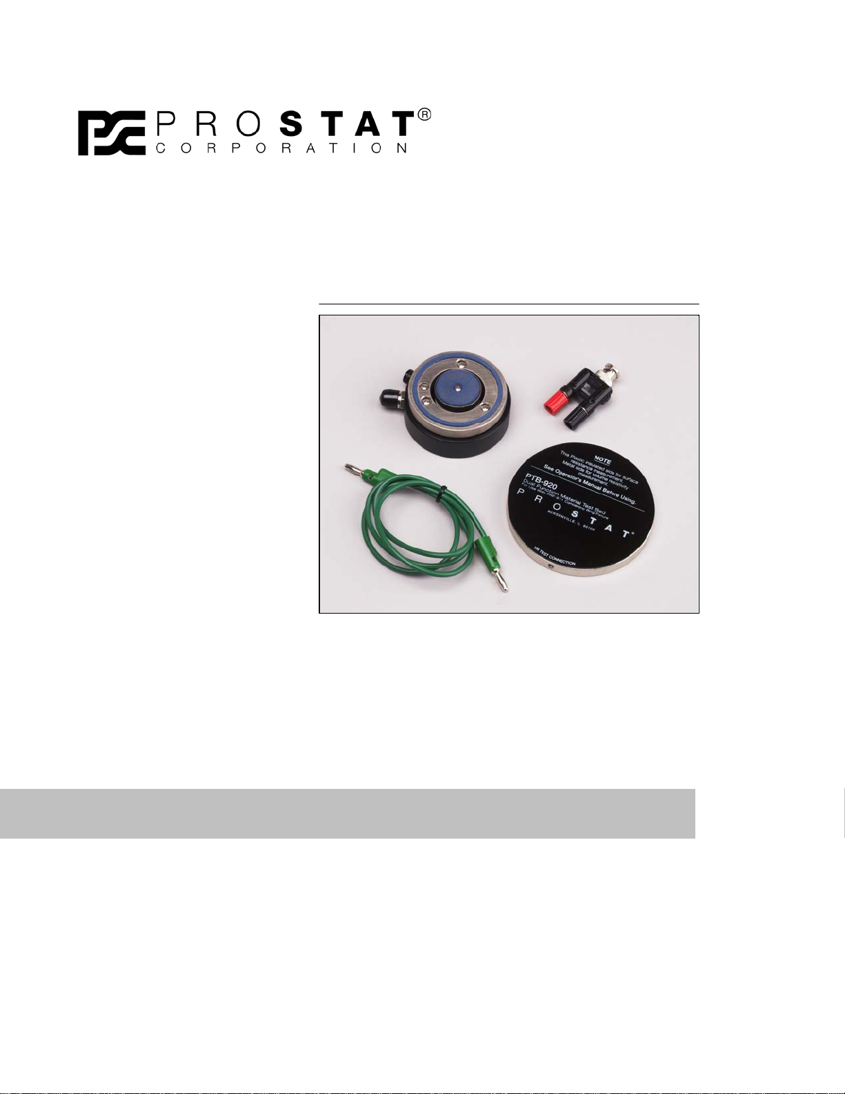
A. PRF-911 Concentric Ring – Equipment and Accessories
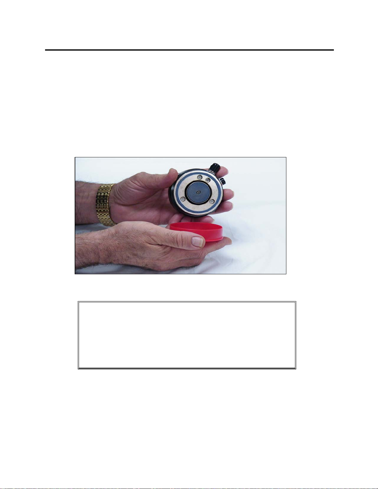
1. PRF-911 Concentric Ring with protective cap
OPERATIONAL HINT
The Red Cap over the Concentric Ring Electrodes
must be removed prior to making a measurement.
The PRF-911 will not operate while the cap is in place.
Replace the red cap for protection when not in use.
2. BNC/Dual Banana terminal adapter allowing "plug-in" connection to the PRF-911
BNC connector as follows:
a. Direct connection to the center INNER RING electrode, designated D1(RED
BNC)
b. The fixture assembly housing ground is designatyed as FIXT.GRD on the unit
label. When properly used, it helps to reduce the effects of extraneous fields on
material measurements (BLACK BNC)
Figure 1: PRF-911 with protective cap

PRF-911 Concentric Ring
6
3. Black banana receptacle in the fixture housing allows direct connection to the
OUTER RING electrode, designated D2.
B. Laminated PTB-920 Dual Test Bed
1. The upper Acrylic insulated surface is
employed during surface resistance
measurements in accordance with ESD
STM 11.11-2001
2. The lower metal surface is equipped with a
standard banana receptacle and is
employed when making volume resistivity
measurements as generally described in
ESD STM 11.12-2000.
C. Inspection of the PRF-911 Concentric Ring Figure 3 Dual Test Bed Fixture
1. Before inspecting the PRF-911 Concentric Ring, confirm the calibration of your
resistance instrument. Performing low Resistance Calibration on the Prostat PRS-
801 and PRS-812 Resistance Instruments.
1. Insert Reference Shunt
2. Select Ohms Mode by pressing “Mode” once
3. Press Test to measure shunt. Indication should be 1.02 Ω+/- 0.002 Ω
4. Press Reset to enter data in memory
5. Press Reset and Clear within ½ second. The display should indicate CAL
6. Press Reset to adjust instrument to reference shunt
7. Press Test to confirm 1.02 Ω+/- 0.02 Ω
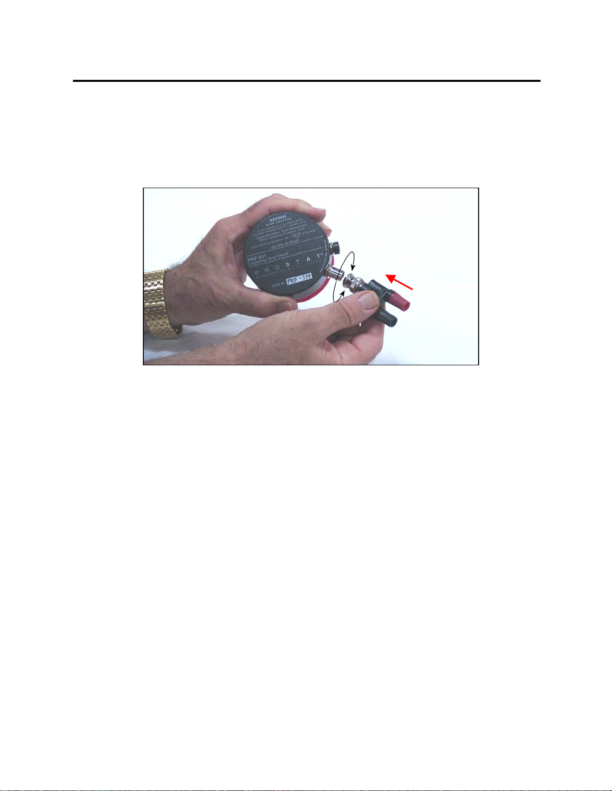
2. Carefully install BNC/Dual Banana adapter on the fixture BNC connector. Note
that the connection is a bayonet type.
Figure 2: BNC adapter and connection
Figure 3: Dual Test Bed
PRF-911 Concentric Ring
7
a. Position adapter on BNC connector while positioning bayonet studs in
the adapter slots
b. Apply slight pressure and twist clockwise to lock the adapter in-place.
c. NOTE: To remove, apply slight pressure and twist counter clockwise.
3. Remove RED protective cap covering the electrode surfaces
4. Confirming the Fixture Ground and BNC Connection
a. Place PRF-911 Concentric Ring fixture on a flat surface with the
electrodes facing UP .
b. Plug one PRS-801 or PRS-812 Resistance Meter test lead to the BLACK
BNC/Dual Banana adapter receptacles.
c. Attach an alligator clip to the second PRS-801 or PRS-812 test lead. NOTE: TO
AVOID DAMAGE, DO NOT ATTACH ALLIGATOR CLIPS TO ANY
SURFACE OR PORTION OF THE PRF-911 FIXTURE.
d.Gently touch the tip of the clip to the metal collar of the BNC adapter
where the connection is made to the fixture housing. (see figure 5)
e. Select Ohms Mode by pressing “Mode” button once.
1. Push Test Button
2. Resistance Should be < 1 Ω
Fi
g
ure 4: Installin
g
the BNC Ada
p
te
r
1
2
PRF-911 Concentric Ring
8
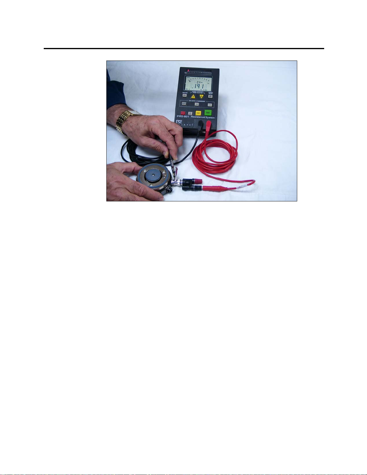
5. Confirming the Center Electrode
Use the following procedure to confirm proper connection to the fixture's center
electrode (D1) through the installed BNC/Dual Banana adapter. NOTE: Review
resistance instrumentr operating instructions before proceeding:
a. Place PRF-911 Concentric Ring fixture on a flat surface with the
electrodes facing UP.
b. Plug one PRS-801 or PRS-812 Resistance Instrument test lead the RED
BNC/Dual Banana adapter receptacle.
c. Attach an alligator clip to the second PRS-801 or PRS-812 test lead. NOTE: TO
AVOID DAMAGE, DO NOT ATTACH ALLIGATOR CLIPS TO ANY
SURFACE OR PORTION OF THE PRF-911 FIXTURE.
d. Hold the second PRS-801 or PRS-812 test lead by the insulated collar just
behind the alligator clip.
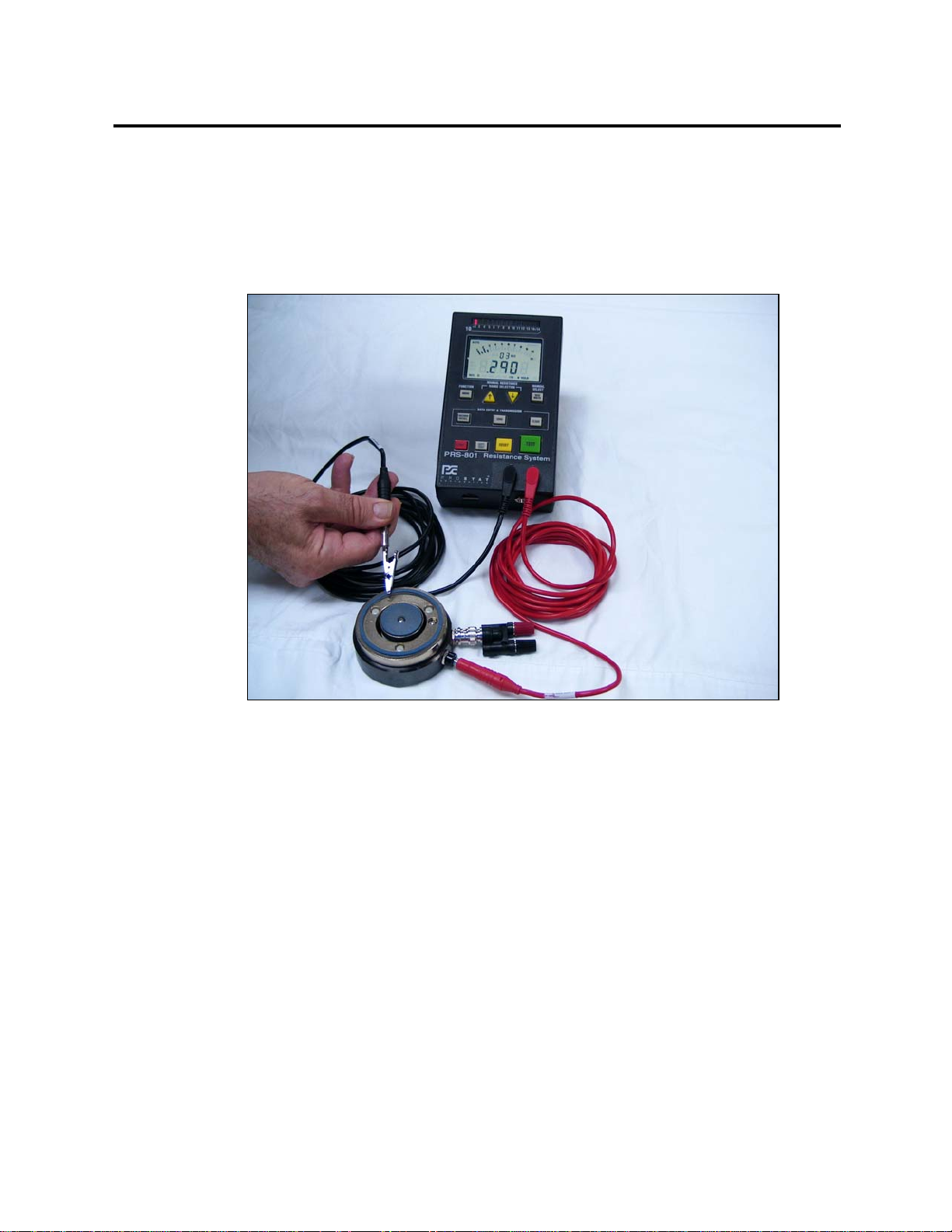
e. GENTLY touch the tip of the alligator clip to the spring loaded center
electrode. (see figure 6)
f. Select Ohms Mode by pressing the “Mode” button once on the PRS-801 or PRS-
812 Resistance Instrument.
1. Push Test Button
2. Resistance Should be < 10 Ω
Figure 5: Confirming Fixture Ground & BNC Connection

PRF-911 Concentric Ring
9
(1) If proper connection is made to the BNC/Dual Banana adapter
the PRS-801 or PRS-812 will indicate low resistance by full meter deflection.
(2) If resistance is high, change the test lead connection to the other BNC/Dual
Banana adapter receptacle and repeat the procedure.
(3) If no continuity indication appears, clean the electrode with 70% solution of
IPA, test the PRS-801 or PRS-812 and lead connections per its operating
instructions and repeat the procedure. (i.e. Install the supplied shunt and test
the low range. Check the cable & connections as well.)
6. Confirming the Outer Electrode
Use the following procedure to confirm proper connection to the fixture's outer ring
electrode (D2) through the frame installed BLACK banana receptacle. NOTE:
Review the resistance instrument’s operating instructions before proceeding.
a. Place PRF-911 Concentric Ring fixture on a flat surface with the
electrodes facing UP .
b. Plug one PRS-801 or PRS-812 Resistance Meter test lead into the BLACK
OUTER RING banana receptacle located in the side of the fixture frame.
c. Attach an alligator clip to the second PRS-801 or PRS-812 Resistance
Instrument test lead. NOTE: TO
AVOID DAMAGE, DO NOT ATTACH ALLIGATOR CLIPS TO ANY
SURFACE OR PORTION OF THE PRF-911 FIXTURE.
Figure 6: Confirming Center Electrode
PRF-911 Concentric Ring
10
d. Hold the second PRS-801 or PRS-812 test lead by the insulated collar just
behind the alligator clip.
e. GENTLY touch the tip of the alligator clip to the narrow outer electrode
ring. (see figure 7)
f. Select Ohms Mode by pressing the “Mode” button once of the PRS-801 or
PRS-812 Resistance Instrument.
1. Push Test Button
2. Resistance Should be < 10 Ω
(1) If proper connection is made through the BLACK receptacle to
the outer ring the PRS-801 or PRS-812 will indicate low.
(2) If no continuity indication appears, clean the electrode with 70% solution of
IPA, test the PRS-801 or PRS-812 per its operating instructions and repeat
the procedure. (i.e. Install the supplied shunt and test the low range. Check
the cable & connections as well.)
Fi
g
ure 7: Confirmin
g
Outer Electrode

PRF-911 Concentric Ring
11
CAUTION
Should the electrode continuity check indicate
improper connection to the electrodes, do not use
the PRF-911 Concentric Ring. Contact PROSTAT
Customer Service Department for further instructions.
7. Confirming Electrode Contact to the Test Bed
Use the following procedure to confirm positive electrode contact with the PTB-920
Test Bed.
a. With the BNC/Dual Banana adapter installed, place the PRF-911 fixture
on the PTB-920 METAL test surface with the electrodes making contact
with the test bed surface.
b. Connect one PRS-801 or PRS-812 Resistance Meter test lead to the center
INNER RING electrode (D1) BNC adapter receptacle (RED)
c. Connect the second PRS-801 or PRS-812 Resistance Meter test lead to the
metal test bed banana receptacle.
d. Place one five pound NFPA electrode on the PRF-911 fixture housing;
(1) NOTE the compression of the center electrode spring assembly
(2) Visually confirm that the outer electrode makes direct contact
with the metal test bed
Figure 8: Confirming Electrode Contact to Test Bed

PRF-911 Concentric Ring
12
e. Select Ohms Mode by pressing the “Mode” button once of the PRS-801 or
PRS-812 Resistance Instrument.
1. Push Test Button
2. Resistance Should be < 20 Ω
(1) If proper connection is made to the BNC/Dual Banana adapter
and the center electrode is in contact with the metal test bed, the
resistance instrument will indicate low resistance.
(2) If proper continuity indication confirms positive contact of the
center electrode to the metal plate, proceed with testing the outer
electrode continuity, as described in point f.
(3) If no continuity indication appears, change the test lead
connection to the other BNC/Dual Banana adapter receptacle
and repeat the procedure.
(4) If no continuity indication appears, clean the electrode surface with 70%
solution of IPA, test the PRS-801 or PRS-812 per its operating instructions
and repeat the procedure. (i.e. Install the supplied shunt and test the low
range. Check the cable & connections as well.)
f. Remove the PRS-801 or PRS-812 test lead from the BNC/Dual Banana adapter
and install it in the BLACK OUTER RING electrode receptacle located on the
side of the fixture housing.
Fi
g
ure 9: Confirmin
g
Electrode Contact to Test Bed

PRF-911 Concentric Ring
13
g. Select Ohms Mode by pressing “Mode” button once.
1. Push Test Button
2. Resistance Should be < 10 Ω
(1) If proper connection is made through the BLACK receptacle to
the outer ring, and the outer electrode is in contact with the
metal test bed, the PRS-801 or PRS-812 will indicate low resistance is < 10 Ω
(2) If proper continuity indication confirms positive contact of the
outer electrode, the fixture check is completed.
(3) If no continuity indication appears, clean the electrode surface with 70%
solution of IPA , test the PRS-801 or PRS-812 per its operating instructions
and repeat the procedure. (i.e. Install the supplied shunt and test the low
range. Check the cable & connections as well.)
IV. General Operation
A. Surface Resistance Measurement per ESD STM 11.11-2001. Note that this procedure
replaces surface resistivity measurements of electrostatic discharge control materials
previously conducted using ASTM D-257. The following procedure is used to measure
surface resistance in ohms, and convert it to ohms/square if necessary.
1. Items necessary for this procedure
a. PRF-911 Concentric Ring Fixture
b. BNC/Dual Banana Adapter
c. PTB-920 Dual Test Bed
d. PRS-801 or PRS-812 Resistance Instrument and test leads
e.One PROSTAT five pound NFPA electrode
f. One GREEN auxiliary ground reference lead or PRS-801 High Resistance Lead
harness if using PRS-801 Instrument. NOTE: Connection to instrument ground
reference is recommended for measurements of 1.0x10 Ωand higher
g. Clear worksurface
2. Specimen Preparation for Surface Resistance measurement
a. This procedure is designed specifically for measuring planar (flat)
surfaces having relatively smooth surfaces.
b. In the laboratory environment, sample preparation usually includes
cutting a 3x5 inch specimen of the sample material to be tested. This
PRF-911 Concentric Ring
14
insures standard specimen size and minimizes fringe voltages that may
effect the surface resistance measurement.
c. In the auditing process, one often must obtain measurement of a large
piece of material without cutting sample into a proper size specimen.
This type of measurement is considered "indicative"; however, it is
sufficient for obtaining a reasonable indication of the material's surface
resistance PROVIDING only one layer of the material is measured as
described below.
3. PRF-911 Concentric Ring Fixture Preparation
a. Install the BNC/Dual Banana adapter on the PRF-911 fixture
b. Check proper battery level of the PRS-801 or PRS-812 Resistance Instrument
and connect the meter leads to the PRF-911 Fixture as follows:
(1) Install the instrument negative (-) lead of the PRS-801 or PRS-812
Resistance Instrument to the RED BNC adapter receptacle connected to the
center INNER RING electrode (D1).
(2) Install the positive (+) lead to the BLACK receptacle connected to the OUTER
RING electrode (D2).
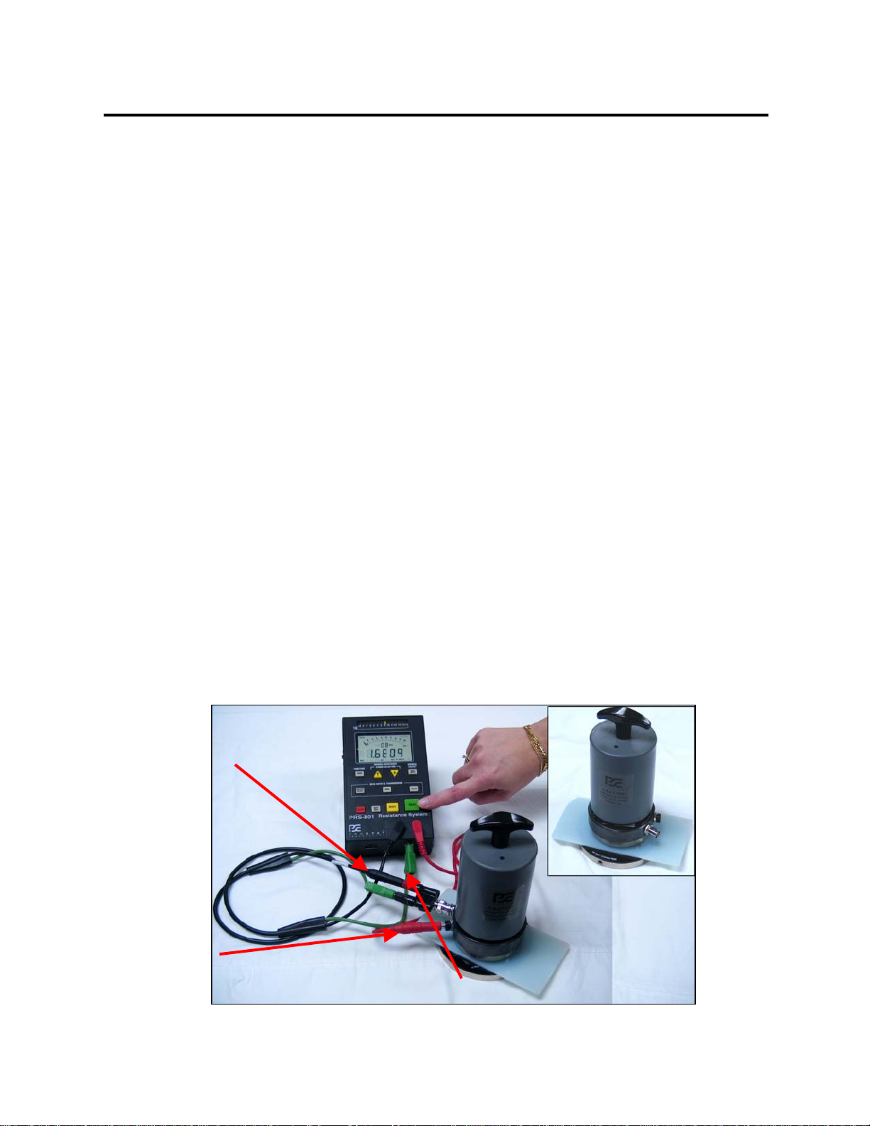
(3) To enhance the accuracy of the measurement, connect a
GREEN auxiliary ground lead to the BNC adapter fixture ground
receptacle, and the other end of the lead to the instrument’s ground
reference, if so equipped.
c. Place the PTB-920 Dual Test Bed on a worksurface with the insulated
acrylic surface facing UP .
Fi
g
ure 10: PRF-911 Fixture Pre
p
aration
Instrument Ground Reference
Positive ( + ) Test
Voltage Power Lead
Negative ( - ) Sensing Lead

PRF-911 Concentric Ring
15
4. To Measure the Material under test
a. Place the specimen to be tested on the insulated PTB-920 test bed with
the surface to be tested facing UP.
b. Remove the protective cap covering the PRF-911 fixture electrodes and
position the fixture on the test material in the approximate center of the
test bed.
c. Place the five pound PROSTAT NFPA electrode directly on top of the
PRF-911 fixture housing. Note the center electrode spring compression
and contact of the outer electrode ring with the material under test.
OPERATIONAL NOTE
The electrode assembly weighs approximately 28
ounces. The center electrode spring counters the
fixture weight with approximately 30 ounces when
fullyextended. When the five pound NFPA electrode
is positioned on the fixture housing, both the outer ring
and the center electrodes have approximately five
pounds total pressure across both surfaces.
d. When operating PRS-801 or PRS-812 Resistance Instruments in Automatic or
Automatic/Manual, simply press the GREEN TEST button to initiate the
measurement sequence.
The initial test voltage will be less than 10 volts (<10V), then increase based on
the material under test resistance range.
Proper test voltage protocol for resistance measurements of ESD Control
materials follows:
Resistance Range (Ω) Test Voltage (V) Remarks
< 1.0 x 10⁴< 10V
Voltage is variable.
Electrification 2-5 sec.
1.0 x 10⁴ to < 1.0 x 10610V Constant Voltage
Preferred. Electrification
2-5 sec.
>1.0 x 106100V
Constant Voltage
Preferred. Electrification
based on system
characteristics

PRF-911 Concentric Ring
16
(1) If the indicated measurement on the PRS-801 or PRS-812 Resistance
Instrument is less than 1.0x10⁶Ohms, record the indicated measurement in
Ohms after approximately 2 to 5 seconds of electrification.
(2) If the indicated measurement on the Resistance Instrument is greater than
1.0x10⁶Ohms:
(a) If using the PRS-801 or PRS-812 Resistance Instrument, in Automatic
Mode the unit will automatically increase the test voltage to 100 Volts, and
control electrification period.
(b) See instrument operations manual for detailed information on resistance
range, test voltage and electrification adjustment details.
5. To estimate Surface Resistivity in Ohms/square when using the ESD STM 11.11-
2001 Surface Resistance Measurement (Ohms), multiply the measurement results
by 10. To accomplish this, simply increase the order of magnitude (exponent) by 1.
For example:
a. If the recorded ESD STM 11.11-2001 Surface Resistance measurement is
2.0x10⁵ Ohms, increase the 105exponent to 106to obtain 2.0x10⁶Ohms/square.
b. If the recorded ESD STM 11.11-2001 Surface Resistance measurement is
5.0x10⁸ Ohms, increase the 108exponent to 109to obtain 5.0x10⁹Ohms/square.
B. Volume Resistivity Measurement per ESD STM 11.12-2000
1. Items necessary for this procedure
a. PRF-911 Concentric Ring Fixture
b. BNC/Dual Banana Adapter
c. PTB-920 Dual Test Bed
d. PRS-801 or PRS-812 Resistance Meter and test leads
e. One PROSTAT five pound NFPA electrode.
f. One GREEN auxiliary ground lead (OPTIONAL)
g. A micrometer to accurately measure the test materials thickness in cm
h. Clear worksurface
2. Specimen Preparation for Volume Resistivity measurement

PRF-911 Concentric Ring
17
a. This procedure is designed specifically for measuring planar (flat)
surfaces having relatively smooth surfaces.
b. In the laboratory environment, sample preparation usually includes
cutting a 3x5 inch specimen of the sample material to be tested. This
insures standard specimen size and minimizes fringe voltages that may
effect the measurement. However, using the outer electrode as a guard ring,
these effects are minimized to some degree.
c. In the auditing process, one often must obtain measurement of a large
piece of material without cutting sample into a proper size specimen.
This type of measurement is considered "indicative"; however, it is
sufficient for obtaining a reasonable indication of the material's volume
resistance.
3. PRF-911 Concentric Ring Fixture Preparation
a. Install the BNC/Dual Banana adapter on the PRF-911 fixture
b. Check proper battery level of the Resistance Instrument and connect its leads
to the PRF-911 Fixture as follows:
(1) Install the negative (-) lead of the PRS-801 or PRS-812 Resistance
Instrument to the RED BNC adapter receptacle connected to the center
electrode (01)'.
(2) Install the positive (+) lead of the PRS-801 or PRS-812 Resistance Instrument
to the banana receptacle located on the edge of the PTB-920 metal test bed.
(3) Install the GREEN auxiliary ground reference lead to the Black BNC
receptacle and the other end of the lead to the instrument ground reference.
c. Place the PTB-920 Dual Test Bed on a worksurface with the conductive
metal surface facing UP.
PRF-911 Concentric Ring
18
4. To Measure the Material under test
a. Place the specimen to be tested on the metal PTB-920 test bed.
b. Remove the PRF-911 fixture electrode protective cap and position the
fixture on the test material in the approximate center of the test bed.
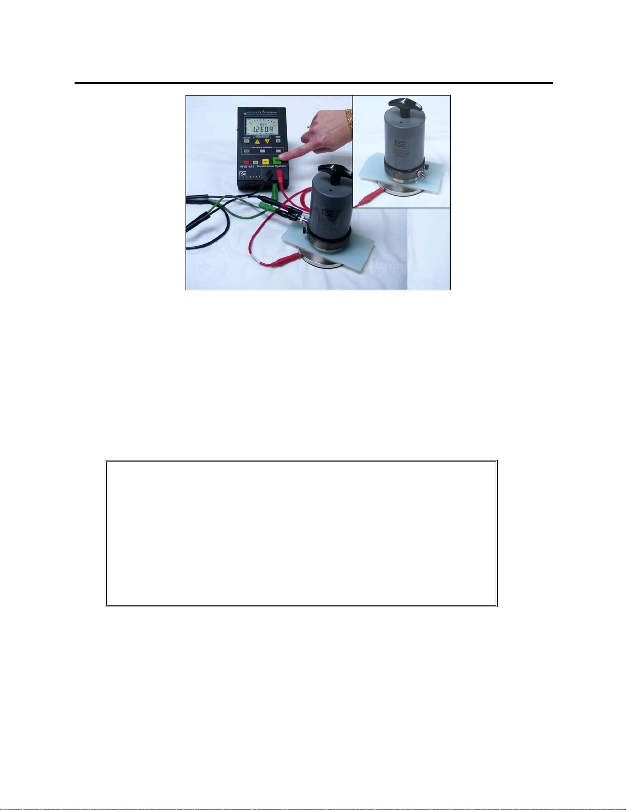
c. Place the five pound PROSTAT NFPA electrode directly on top of the
PRF-911 fixture housing. Note the center electrode spring compression
and contact of the outer electrode ring with the material under test.
OPERATIONAL NOTE
The electrode assembly weighs approximately 28
ounces. The center electrode spring counters the
fixture weight with approximately 30 ounces when
fully extended. When the five pound NFPA electrode
is positioned on the fixture housing, the outer ring and
center electrodes have approximately five pounds total
pressure across both surfaces.
d. Select Test while in the Automatic Mode -- be sure no personnel are in contact
with the material or PRF-911.
Figure 11: Fixture Preparation (Continued)
PRF-911 Concentric Ring
19
OPERATIONAL WARNING
TO AVOID PERSONNEL SHOCK, DO NOT TOUCH
THE MATERIAL UNDER TEST, THE PRF-911
CONCENTRIC FIXTURE OR TEST BED DURING
ANY MEASUREMENT CYCLE.
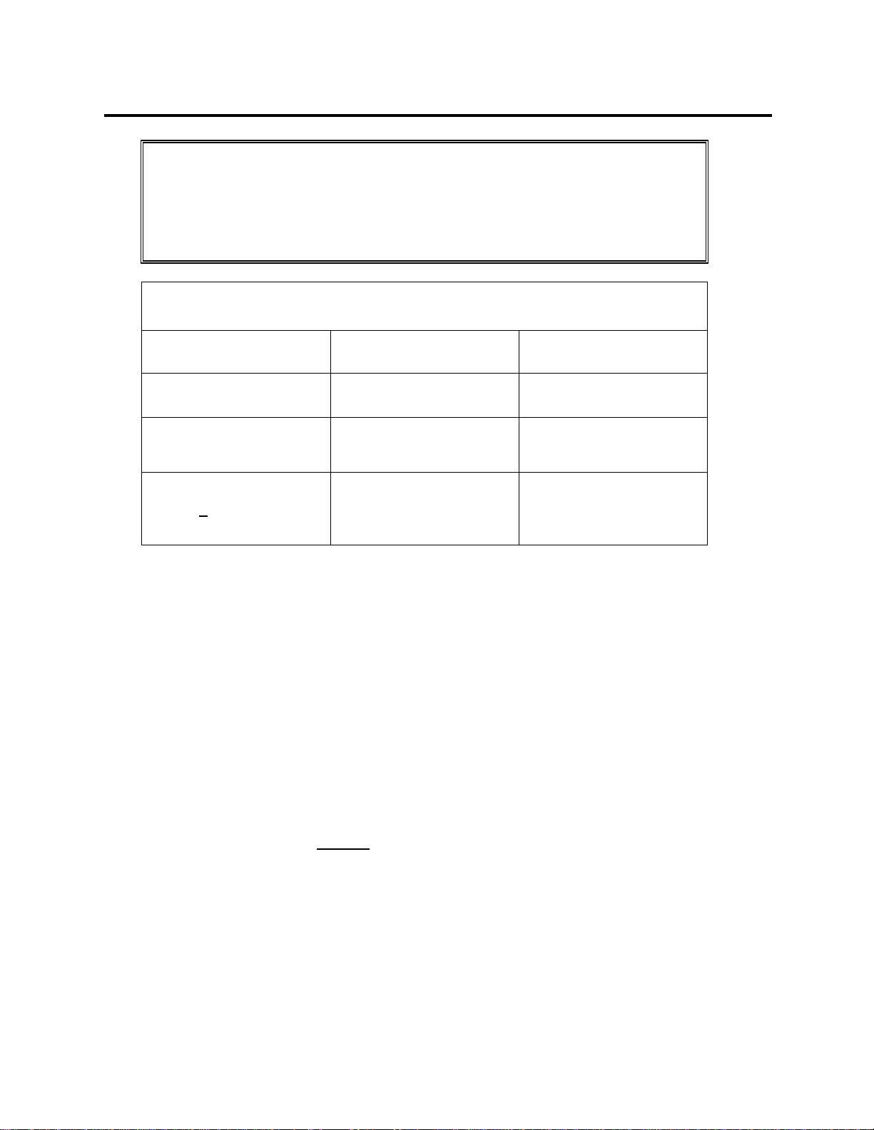
Proper test voltage protocol for resistance measurements of ESD Control
materials follows:
Resistance Range (Ω) Test Voltage (V) Remarks
< 1.0 x 10⁴< 10V
Voltage is variable.
Electrification 2-5 sec.
1.0 x 10⁴ to < 1.0 x 10610V Constant Voltage
Preferred. Electrification
2-5 sec.
>1.0 x 106100V
Constant Voltage
Preferred. Electrification
based on system
characteristics
(1) If the indicated measurement on the PRS-801 or PRS-812 Resistance
Instrument is less than 1.0x10⁶Ohms, record the indicated measurement in
Ohms after approximately 2 to 5 seconds of electrification.
(2) If the indicated measurement on the PRS-801 or PRS-812 Resistance
Instrument is greater than 1.0x10⁶Ohms:
(a) Select 100 Volts on the test instrument if using PRS-801 or PRS-812
Resistance Instruments. They will automatically shift to 100 Volts.
(b) After instrument’s electrification record the indicated measurement in
Ohms.
5. To calculate Volume Resistivity in Ohms-cm use the following formula.
Volume
Resistivity = 6.9 cm2x RIOhm
in Ohm-cm t cm
where,
6.9 cm2is the AREA of the center electrode's (D1) contact surface with
the material
t = The thickness of the material in centimeters (cm)
RI= The Resistance as indicated on the PRS-801 or PRS-812 or the
Resistance Instrument of choice in ohms.
Table of contents
Other Prostat Cables And Connectors manuals


