Prostat PWA-805 User manual
User Manual
PWA-805
WRIST STRAP AUDITOR FIXTURE


Page
I. Before Using the Instrument 4
II. Safery 4
III. Descripon 4
IV. Accuracy 5
V. Baery Installaon & General Maintenance 6
VI. Normal Operaons 7
VII. Funconally Tesng the PMT-872A 13
General Specicaons 17
Copyright © 2012 by Prostat® Corporaon. All rights reserved. Printed in the United States of America. No part of this
manual may be used or reproduced in any manner whatsoever without wrien permission. For informaon contact
Prostat Corporaon, 1072 Tower Lane, Bensenville, IL 60106 USA
Prostat is the registered trademark of Prostat® Corporaon

4Rev. A / January 1995
PWA-805 Wrist Strap Auditor Fixture
The Prostat PWA-805 Wrist Strap Auditor is designed to determine the condion of a wrist strap as-
sembly. Used with the PRS-801 or PRS-812 Resistance Meters, a resistance measurement can be made
of the full assembly cu and cord, the cu only, or the cord only. This measurement will dene the
operable condion of any standard wrist strap.
A. The PWA-805 unit approximates the basic electrical measurement requirements of the ANSI/ESD
S1.1 wrist strap standard.
B. The intent of the PWA-805 is to provide the ESD auditor with a convenient xture to measure the
exact resistance characteriscs of a wrist strap, rather than generally esmate its approximate
resistance range with an indicang checker.
C. The PWA-805 will provide the four following resistance measurements:
1. Resistance of a wrist strap from the inner, middle posion of the cu to the end of the ground-
ing cord.
2. The resistance between two points on the inner surface of the cu
3. The resistance between two points on the outer surface of the cu
4. The resistance between the cord cu snap and ground connecon
A. As with any electrical device, use proper electrical precauons to avoid personnel shock.
1. The PWA-805 Wrist Strap Auditor xture operates with power input from the Resistance Meter
at 10 to 100 volts, and is capable of delivering an annoying shock to any person touching it.
2. Although the current capability is limited, a disnct HAZARD EXISTS in the person’s reacon to
the shock.
3. To avoid personnel shock, do not touch the can electrodes when power is applied to the xture
To avoid electrical shock, do not touch the xture’s
can electrodes when power is being applied.
B. The PWA-805 is designed to be used in audit environments at test voltages of 100 volts or less.
Exceeding 100 volts greatly enhances the risk of personnel shock hazards and may damage the
xture.
Operaonal test voltages should not exceed
100 volts in the audit environment.

5
Rev. A / January 1995
PWA-805 Wrist Strap Auditor Fixture
C. DO NOT USE THE PWA-805 AUDITOR if it fails to pass its funconal test.
Should the Funconal connuity check indicate improper operaon of the x-
ture, OR the xture becomes damaged, do not use the PWA-805.
Contact Prostat Customer Service Department for further instrucons.
D. DO NOT USE THE PWA-805 AUDITOR if it becomes damaged in any way.
E. Only qualied instrument repair personnel should open terminal connecons or repair the PWA-
805 AUDITOR.
F. Do not store or use in damp environments
G. Always store the PWA-805 in its protecve case.
A. Basic Descripon
The PWA-805 Wrist Strap Auditor Fixture consists of two metal cylinder electrodes mounted on a
plasc base and wired to a switch, cord connecon points and meter input receptacles.
1. The metal cylinder (can) electrodes are used to mount wrist strap cus for connuity and resis-
tance measurements.
2. A YELLOW cord receptacle allows the wrist strap grounding cord to be plugged into the xture’s
test circuit.
3. Two meter input receptacles (RED and BLACK) are provided to connect the Resistance Meter
to the xture’s test circuit. The Resistance Meter provides all resistance measurements for the
PWA-805 Auditor.
4. Two male snap posts, one 7 mm and one 4 mm, are provided for mounng the cu snap end
of the grounding cord to the xture circuit during Cord Only measurements.
5. A three posion rocker switch (BLACK) allows resistance measurements of the following wrist
strap components:
a. The Cu and Grounding Cord
b. The Cu Only
c. The Grounding Cord Only

6Rev. A / January 1995
PWA-805 Wrist Strap Auditor Fixture
B. Funconal Test of the PWA-805 Wrist Strap Auditor Fixture
1. Funconal Connuity Test of the CUFF & CORD measurement funcon.
a. Connect the test leads from the Resistance Meter to the PWA-805 Auditor METER recep-
tacles. NOTE: Prior to using the Resistance Meter, read the Operaons Manual.
b. Plug an auxiliary test lead into the YELLOW CORD receptacle. Use a straight test lead
equipped with banana plugs. For ease of handling install an alligator clip on one end of the
test lead.
c. Select the CONTINUITY TEST posion on the Resistance Meter.
d. Touch the free end of the installed test lead to the PWA-805 adjustable can electrode (the
can on the right side of the xture equipped with a knurled, sloed locking screw).
e. Select the xture rocker switch middle posion, labeled CUFF & CORD.

7
Rev. A / January 1995
PWA-805 Wrist Strap Auditor Fixture
f. Push the TEST buon on the Resistance Meter. The Resistance Meter should indicate 0
Ohms.
To avoid electrical shock, do not touch the xture,
can electrodes when power is being applied.
(1) If the Resistance Meter indicates 0 Ohms, the connuity test for the CUFF & CORD
test funcon is acceptable. Proceed to the CORD ONLY funconal test.
(2) If the meter indicates “innity” or a high resistance check the rocker switch posion
and test lead connecons and repeat the connuity test.
(3) If the Resistance Meter does not indicate 0 Ohms, do not use the PWA-805 Auditor.
Contact Prostat Customer Service.
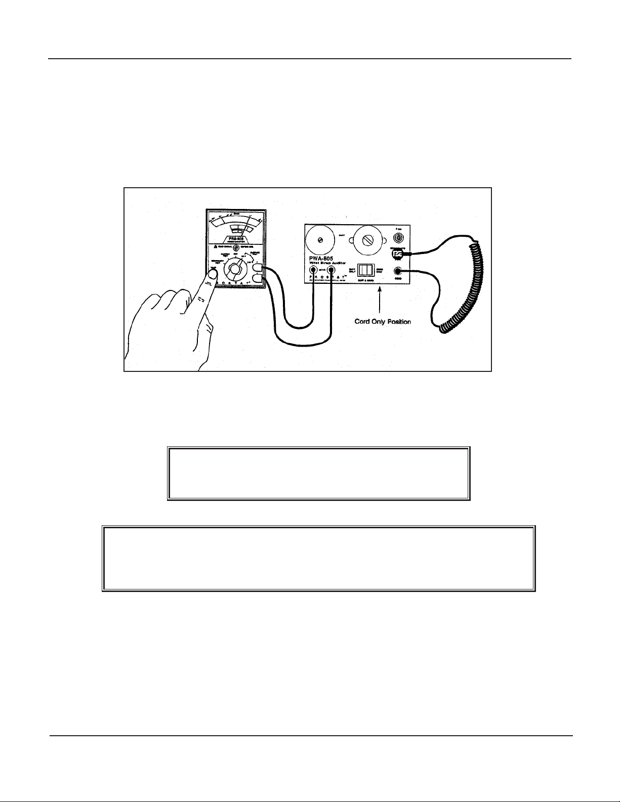
2. Funconal Connuity Test of the CORD ONLY measurement funcon.
a. Connect the test leads from the Resistance Meter to the PWA-805 Auditor METER recep-
tacles. NOTE: Prior to using the Resistance Meter, read the Operaons Manual.
b. Plug an auxiliary test lead into the YELLOW CORD receptacle. Use a straight test lead
equipped with banana plugs. For ease of handling, install an alligator clip on one end of the
test lead.
c. Select the CONTINUITY TEST posion on the Resistance Meter.
d. Touch the free end of the installed test lead to the PWA-805 7 mm male CORD SNAP termi-
nal.
e. Select the xture rocker switch right posion, labeled CORD ONLY.
f. Push the TEST buon on the Resistance Meter. The Resistance Meter should indicate 0
Ohms.

8Rev. A / January 1995
PWA-805 Wrist Strap Auditor Fixture
To avoid electrical shock, do not touch the xture
can electrodes when power is being applied.
(1) If the Resistance Meter indicates 0 Ohms, the connuity test for the 7 mm CORD
ONLY test funcon is acceptable. Proceed to the 4 mm CORD ONLY funconal test.
(2) If the meter indicates “innity” or a high resistance check the rocker switch posion
and test lead connecons and repeat the connuity test.
(3) If the Resistance Meter does not indicate 0 Ohms, do not use the PWA-805 Auditor.
Contact Prostat Customer Service.
g. Touch the free end of the installed test lead to the PWA-805 4 mm male CORD SNAP termi-
nal.
h. Select the xture rocker switch right posion, labeled CORD ONLY.
i. Push the TEST buon on the Resistance Meter. The Resistance Meter should indicate 0
Ohms.
To avoid electrical shock, do not touch the xture
can electrodes when power is being applied.
(1) If the Resistance Meter indicates 0 Ohms, the connuity test for the 4 mm CORD
ONLY test funcon is acceptable. Proceed to the CUFF ONLY funconal test.
(2) If the meter indicates “innity” or a high resistance check the rocker switch posion
and test lead connecons and repeat the connuity test.
(3) If the Resistance Meter does not indicate 0 Ohms, do not use the PWA-805 Auditor.
Contact Prostat Customer Service.
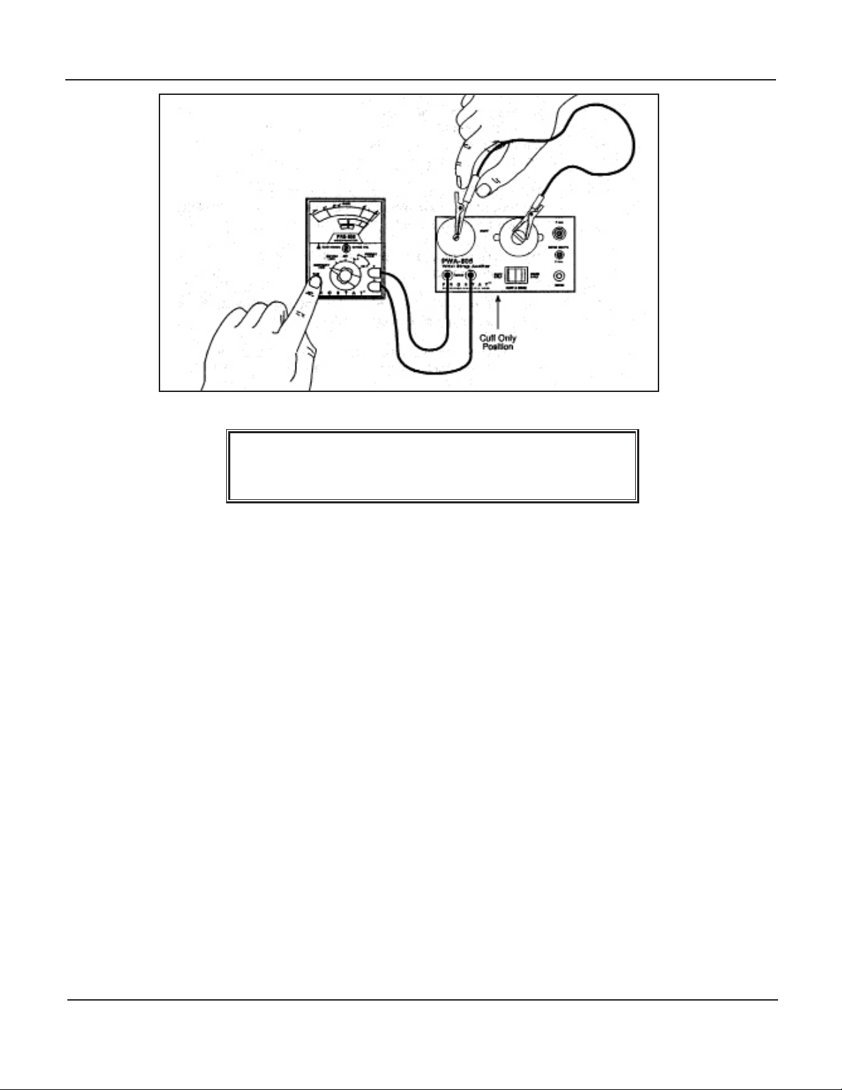
3. Funconal Connuity Test of the CUFF ONLY measurement funcon.
a. Connect the test leads from the Resistance Meter to the PWA-805 Auditor METER recep-
tacles. Prior to using the Resistance Meter, read the Operaons Manual.
b. Aach an auxiliary test lead to the adjustable can electrode (right side of the xture). Use a
straight test lead equipped with banana plugs and two alligator clip.
c. Select the CONTINUITY TEST posion on the Resistance Meter.
d. Touch the free end of the installed test lead to the PWA-805 xed can electrode (the can on
the le side of the xture).
e. Select the xture rocker switch le posion, labeled CUFF ONLY.
f. Push the TEST buon on the Resistance Meter. The Resistance Meter should indicate 0
Ohms.
9
Rev. A / January 1995
PWA-805 Wrist Strap Auditor Fixture
To avoid electrical shock, do not touch the xture
can electrodes when power is being applied.
(1) If the Resistance Meter indicates 0 Ohms, the connuity test for the CUFF ONLY test
funcon is acceptable, and all funconal tests are completed.
(2) If the meter indicates “innity” or a high resistance check the rocker switch posion
and test lead connecons and repeat the connuity test.
(3) If the Resistance Meter does not indicate 0 Ohms, do not use the PWA-805 Auditor.
Contact Prostat Customer Service.
A. General
1. This operaon will provide the four following resistance measurements:
a. Resistance of a wrist strap from the inner surface, middle posion of the cu to the end
of the grounding cord. This measurement indicates the maximum resistance between the
user and an ESD common ground point.
b. The resistance between two points on the inner surface of the cu. Properly used, this
measurement denes the connuity of the inner cu’s surface between 2 points, 180
°
apart.
(1) Thus, proper connecons of the cu to the wrist buckle may be conrmed.
(2) The connuity around the enre perimeter of the inner cu surface may be
conrmed.

10 Rev. A / January 1995
PWA-805 Wrist Strap Auditor Fixture
c. The resistance between two points on the outer surface of the cu. This measurement
conrms the insulave characteriscs of the cus outer surface.
d. The resistance between the ground cord’s cu snap and its connecon to ground. This
measurement performs two funcons.
(1) It allows the operator to check the ground cord for “opens”
(2) It measures the total resistance of the ground cord conductor resistor and
connecon points.
2. The following procedures require the use of the Resistance Meter. Be sure to read its Opera-
ons Manual and perform its Funconal Test prior to using.
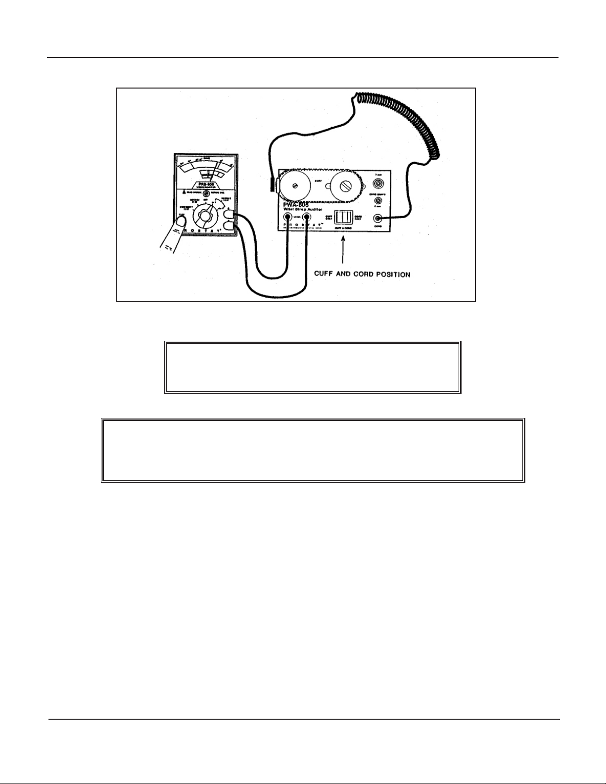
B. Resistance Measurement of a wrist strap assembly CUFF & CORD.
1. Connect the test leads from the Resistance Meter to the PWA-805 Auditor RED and BLACK
METER receptacles.
2. Place the rocker switch in the middle CUFF & CORD posion
The LEFT can electrode in the CUFF & CORD measurement Mode is used to hold the cu me-
chanically; it is not in the measurement circuit. The RIGHT can electrode is in the measure-
ment circuit. Consequently, the inner cu surface must contact the
RIGHT can electrode to obtain an accurate measurement.
3. Mount the wrist strap cu to the PWA-805 xture as follows:
a. Loosen the adjustable RIGHT can electrode and slide it toward the LEFT can electrode.
b. Posion the inner surface of the cu buckle against the LEFT can electrode and hold it
rmly in posion with your le hand.
c. With your right hand, stretch the cu over and onto the adjustable RIGHT can electrode.
d. Slide the adjustable RIGHT can electrode toward the right side of the xture unl there are
1 to 2 pounds of tension on the wrist strap cu.
e. Tighten the RIGHT can electrodes locking screw.
4. Plug the wrist strap’s ground cord banana plug into the YELLOW CORD receptacle.
5. The wrist strap is now mounted on the PWA-80S xture. Be sure:
a. The cu is posioned smoothly on the sides of the two can electrodes
b. The ground cord is properly aached to the cu buckle
c. The ground cord banana plug is fully inserted into the YELLOW CORD receptacle.
6. Select the 10 volt posion on the Resistance Meter and push the TEST buon to obtain a resis-
tance measurement.
11
Rev. A / January 1995
PWA-805 Wrist Strap Auditor Fixture
To avoid electrical shock, do not touch the xture
can electrodes when power is being applied.
During the measurement, one might wish to check for “opens” in the ground cord
or poor connecons by stretching various parts of the cord and observing the
meter indicaon. Wiggling the snap connecons may indicate a loose ng snap.
a. Most US wrist straps are designed to measure approximately 1.0x10⁶ Ohms, ±20 percent,
i.e., 8.0x10⁵ to 1.2x10⁶ Ohms.
b. Specially designed wrist straps used in munions are lower in resistance, while others are
designed for higher resistance levels, as in some internaonal markets.
c. Defecve wrist straps will measure well above 1.0x10⁷ Ohms. CHECK YOUR ESD OPERA-
TIONS STANDARDS TO DEFINE THE PROPER RESISTANCE RANGE FOR OPERATIONAL WRIST
STRAP ASSEMBLIES.
d. If the wrist strap indicates defecve, or you wish to further dene the wrist strap’s charac-
teriscs, proceed with the following measurements.
C. Resistance Measurement of the wrist strap CUFF ONY, Inner Surface.
1. Connect the test leads from the Resistance Meter to the PWA-805 Auditor RED and BLACK

12 Rev. A / January 1995
PWA-805 Wrist Strap Auditor Fixture
METER receptacles.
2. Place the rocker switch in the CUFF ONLY (le) posion
In this Measurement Mode both the LEFT and the RIGHT
can electrodes are in the measurement circuit.
3. Mount the wrist strap cu to the PWA-805 xture as follows:
a. Loosen the adjustable RIGHT can electrode and slide it toward the LEFT can electrode.
b. Posion the inner surface of the cu buckle against the LEFT can electrode and hold it
rmly in posion with your le hand.
c. With your right hand, stretch the cu over and onto the adjustable RIGHT can electrode.
d. Slide the adjustable RIGHT can electrode toward the right side of the xture unl there are
1 to 2 pounds of tension on the wrist strap cu.
e. Tighten the RIGHT can electrodes locking screw.
4. Disconnect the wrist strap’s ground cord from the cu buckle.
5. The wrist strap cu is now mounted on the PWA-805 xture. Be sure the cu is posioned
smoothly on the sides of the two can electrodes.
6. Select the 10 volt posion on the Resistance Meter and push the TEST buon to obtain a resis-
tance measurement.

13
Rev. A / January 1995
PWA-805 Wrist Strap Auditor Fixture
To avoid electrical shock, do not touch the xture
can electrodes when power is being applied.
a. Most US wrist strap cus are designed to indicate very conducve, well below 1.0x10⁵
Ohms.
b. Defecve wrist strap cus will measure well above 1.0x10⁶ Ohms. CHECK YOUR ESD OPERA-
TIONS STANDARDS TO DEFINE THE PROPER RESISTANCE RANGE FOR OPERATIONAL WRIST
STRAP ASSEMBLIES.
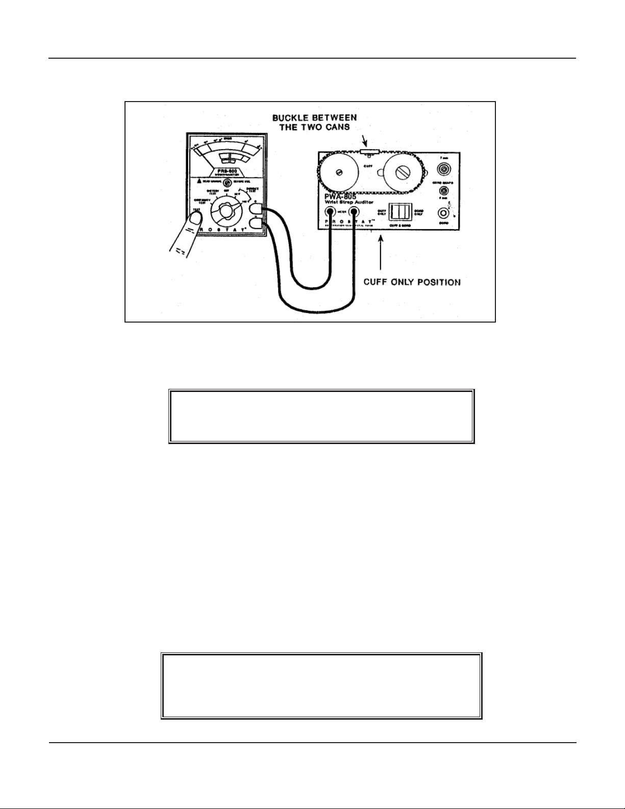
c. Reposion the cu by sliding it 90 degrees around the can electrodes. Repeat the cu mea-
surement with buckle between cans.
D. Resistance Measurement of the wrist strap CUFF ONLY, Outer Surface.
1. Connect the test leads from the Resistance Meter to the PWA-805 Auditor RED and BLACK
METER receptacles.
2. Place the rocker switch in the CUFF ONLY (le) posion
In this Measurement Mode both the LEFT and the RIGHT
can electrodes are in the measurement circuit.
3. Mount the wrist strap cu to the PWA-805 xture as follows. Note: Be sure the ground cord is
disconnected.
a. Loosen the adjustable RIGHT can electrode and slide it toward the LEFT can electrode.
b. Posion the outer surface of the cu against the LEFT can electrode and hold it rmly in
posion with your le hand. Posion the buckle between the 2 cans.
c. With your right hand, stretch the cu over and onto the adjustable RIGHT can electrode.
Posion the cu buckle between the can
electrodes to prevent the buckle from aecng the
outer cu resistance measurement.
d. Slide the adjustable RIGHT can electrode toward the right side of the xture unl there are
1 to 2 pounds of tension on the wrist strap cu.
e. Tighten the RIGHT can electrodes locking screw.
14 Rev. A / January 1995
PWA-805 Wrist Strap Auditor Fixture
4. The wrist strap cu is now mounted on the PWA-805 xture. Be sure the cu is posioned
smoothly on the sides of the two can erectrodes and the buckle is between the cans.
5. Select the 10 volt posion on the Resistance Meter and push the TEST buon to obtain a resis-
tance measurement.
To avoid electrical shock, do not touch the xture
can electrodes when power is being applied.
a. Most US wrist strap cu outer surfaces are designed to indicate high resistance (insulave)
and measure well above 1.0x10⁹ Ohms.
b. Defecve wrist strap cus will measure well below 1.0x10⁹ Ohms. CHECK YOUR ESD OPERA-
TIONS STANDARDS TO DEFINE THE PROPER RESISTANCE RANGE FOR OPERATIONAL WRIST
STRAP ASSEMBLIES.
6. Repeat the outer cu surface measurements at 100 volts.
E. Resistance Measurement of a wrist strap ground cord, i.e., CORD ONLY
1. Connect the test leads from the Resistance Meter to the PWA-805 Auditor RED and BLACK
METER receptacles.
2. Place the rocker switch in the right CORD ONL Y posion
In this measurement mode, both the 7 mm and the 4 mm
CORD SNAPs, as well as the YELLOW CORD receptacle
are in the measurement circuit.
15
Rev. A / January 1995
PWA-805 Wrist Strap Auditor Fixture
3. Do Not Mount the wrist strap cu to the PWA-805 xture for this test. If it is mounted, it is not
part of the measurement circuit and may remain in posion.
4. Plug the wrist strap’s ground cord banana plug into the YELLOW CORD receptacle.
5. Aach the buckle connecon snap assembly to either the 7 mm or 4 mm snap post.
6. The wrist strap ground cord is now mounted on the PWA-805 xture. Be sure: The ground cord
banana plug is fully inserted into the YELLOW CORD receptacle.
7. Select the 10 volt posion on the Resistance Meter and push the TEST buon to obtain a resis-
tance measurement.
To avoid electrical shock, do not touch the xture
can electrodes when power is being applied.
During the measurement, one might wish to check for “opens” in the ground cord
or poor connecons by stretching various parts of the cord and observing the
meter indicaon. Wiggling the snap connecons may indicate a loose ng snap.
a. Most US wrist strap cord assemblies are designed to measure approximately 1.0x10⁶ Ohms,
±20 percent, i.e., 8.0x10⁵ to 1.2x10⁶ Ohms.
b. Specially designed wrist straps used in munions are lower in resistance, while others are
designed for higher resistance levels, as in someinternaonal markets.
c. Defecve wrist straps will measure well above 1.0x10⁷ Ohms. CHECK YOUR ESD OPERA-
TIONS STANDARDS TO DEFINE THE PROPER RESISTANCE RANGE FOR OPERATIONAL WRIST
STRAP ASSEMBLIES.

16 Rev. A / January 1995
PWA-805 Wrist Strap Auditor Fixture
The user serviceable parts in the PWA-80S Wrist Strap Auditor are basically terminal connecons.
A. Care should be take to keep all connecons free from dirt and dust.
B. Occasionally a snap post may loosen. Tighten with a an appropriate screw driver. The xture case
may require opening to lock terminal connecons.
C. If in doubt, contact Prostat Customer Service for assistance or return of the unit.
Fixture Case: 4.6” L x 2.75” W x 0.95” H inches
Wrist Strap Two (2) top mounted metal cylinders: 1 xed, 1 adjustable for cu size
Cylinders: Cylinder Diameter: 1.25. x 1.0. H
Adjustable cylinder equipped with knurled locking screw for posioning
Comtrols: Three posion rocker switch: (1) Cu Only [Resistance between Cylinders]
(2) Cu & Cord Assembly [Resistance from cord ground point to cu cylinder];
(3) Cord Only [Resistance from cord ground point to cu snap connecons]
Connecons: Resistance Meter: 2 banana receptacles for meter leads
Cord Groundable Point: 1 banana receptacle
2 Cord Cu Snaps: 1 each 7mm diameter, 1 each 4mm diameter
Power: Not Applicable. The xture is used in conjuncon with the Resistance Meter and
test leads.
Weight: 4.5 oz.
Warranty: One year limited warranty

17
Rev. A / January 1995
PWA-805 Wrist Strap Auditor Fixture

18 Rev. A / January 1995
PWA-805 Wrist Strap Auditor Fixture


PROFESSIONAL STATIC CONTROL PRODUCTS
Corporate Headquarters • 1072 Tower Lane • Bensenville, IL 60106 • 630-238-8883 • Fax: 630-238-9717 • 1-855-STATIC1 • www.prostatcorp.com
Prostat Corporaon
Specicaons are subject to change without noce.
All Prostat trademarks and trade names are the property of Prostat Corporaon.
All other trademarks and trade names are the property of their respecve companies.
Other manuals for PWA-805
1
Other Prostat Test Equipment manuals


