Messwertumformer MUW
Anschlusshinweise
1. Vorbereitung des Anschlusskabels
Empfohlen wird ein 3- oder 4-adrig verdrilltes Kabel (0,25 mm²) mit Schirmgeflecht und einem
Außendurchmesser von 4 bis 10 mm. Schrauben Sie die Kunststoffschraube der PG–Verschraubung
von der Leitungsdose ab und schieben Sie sie mit der Unterlegscheibe und dem Stopfbuchseneinsatz
über das Kabelende. Entfernen Sie 30 mm der Kabelummantelung und isolieren Sie 5 mm der Litzen
ab, verdrillen Sie ggf. das Schirmgeflecht. Benutzen Sie Aderendhülsen (0,5 und 0,75 mm² für die
Schirmung). Bei 4-adrigem Kabel sind beide Massedrähte für Klemme B in eine gemeinsame
Aderendhülse zu quetschen. Schieben Sie den in der Dose liegenden Schrumpfschlauch über die
Schirmung.
2. Öffnen der Leitungsdose
Ziehen Sie die Befestigungsschraube bei geschlossenem Deckel vollständig aus der Leitungsdose
heraus; heben Sie den Deckel ab.
3. Anschließen des Kabels
Entfernen Sie die Zugentlastungslasche ( 2 Kreuzschlitzschrauben) im Innern der Dose. Führen Sie das
wie unter (1.) vorbereitete Kabel in die Kabeldose ein. Schließen Sie die Litzen entsprechend dem
Anschlussschema (siehe unten) an der Klemmleiste an. Schieben Sie das Kabel soweit vor, dass die
Kabelummantelung in den Bereich der Kabelzugentlastung kommt; montieren Sie die Zugentlastungs-
lasche (für Kabel Ø < 5 mm wenden). Schieben Sie den Stopfbuchseneinsatz und die Unterlegscheibe
in die Kabeldose und verschrauben Sie ihn dicht mit der Kunststoffschraube.
4. Drehen des Buchseneinsatzes
Falls erforderlich, können Sie die Orientierung des Kabels durch Drehen des Buchseneinsatzes
folgendermaßen ändern: öffnen Sie die Leitungsdose, wie unter (2.) beschrieben. Drücken Sie den
Buchseneinsatz durch die Bohrung in der Mitte der Platine nach unten. Drehen Sie den Buchseneinsatz
in die gewünschte Position. Achten Sie beim Einsetzen darauf, keine Litzen einzuklemmen. Der Einsatz
sitzt etwa 1mm vertieft in der Dose.
5. Befestigung der Leitungsdose am Messwertaufnehmer
Schließen Sie den Deckel der Leitungsdose und stecken Sie die Befestigungsschraube ein. Legen Sie
die beiliegende Dichtung auf den Stecker, stecken Sie die Leitungsdose auf und schrauben Sie sie mit
der Befestigungsschraube fest.
6. Vertauschen der Wirkrichtung
Soll die Zuordnung des Ausgangssignals zur Bewegungsrichtung des Aufnehmers geändert werden, so
ist folgendermaßen vorzugehen: Nehmen Sie den Buchseneinsatz wie unter (4.) beschrieben heraus.
Vertauschen Sie die Litzen 1 (schwarz) und 3 (blau) am Buchseneinsatz. Wiedermontage wie unter (4.)
beschrieben.
7. Justierung (nur MUW250)
Justieren Sie zunächst den Nullpunkt: Bewegen Sie dazu den Schleifer des Aufnehmers in die
Anfangsposition. Achten Sie unbedingt darauf, dass sich der Schleifer innerhalb des elektrischen
Messbereichs des Sensors befindet.
Bei den Typen MUW250-0 und MUW250-1 justieren Sie nun das Ausgangssignal durch Verstellen des
Trimmpotis neben der Klemme D auf 0 V. Drehen Sie nicht über 0 V hinaus. Bewegen Sie den Schleifer
des Aufnehmers in die Endposition. Achten Sie auch hier auf den elektrischen Bereich des Sensors.
Justieren nun das Ausgangssignal mit Hilfe des Trimmpotis neben der Klemme A auf 10 V.
Beim Typ MUW250-4 gehen Sie bitte folgendermaßen vor: Bewegen Sie den Schleifer des
Aufnehmers in die Anfangsposition. Justieren Sie das Ausgangssignal mit dem Trimmer neben der
Klemme D auf
0 mA. Bringen Sie dann den Schleifer in die Endposition. Justieren Sie jetzt den Strom mit dem
Trimmpoti neben der Klemme A auf 16 mA. Bewegen Sie den Schleifer in die Anfangsposition und
justieren Sie den Strom mit dem Trimmpoti neben Klemme D auf 4 mA. Überprüfen Sie den Wert in der
Endposition und wiederholen Sie ggf. diesen Vorgang.
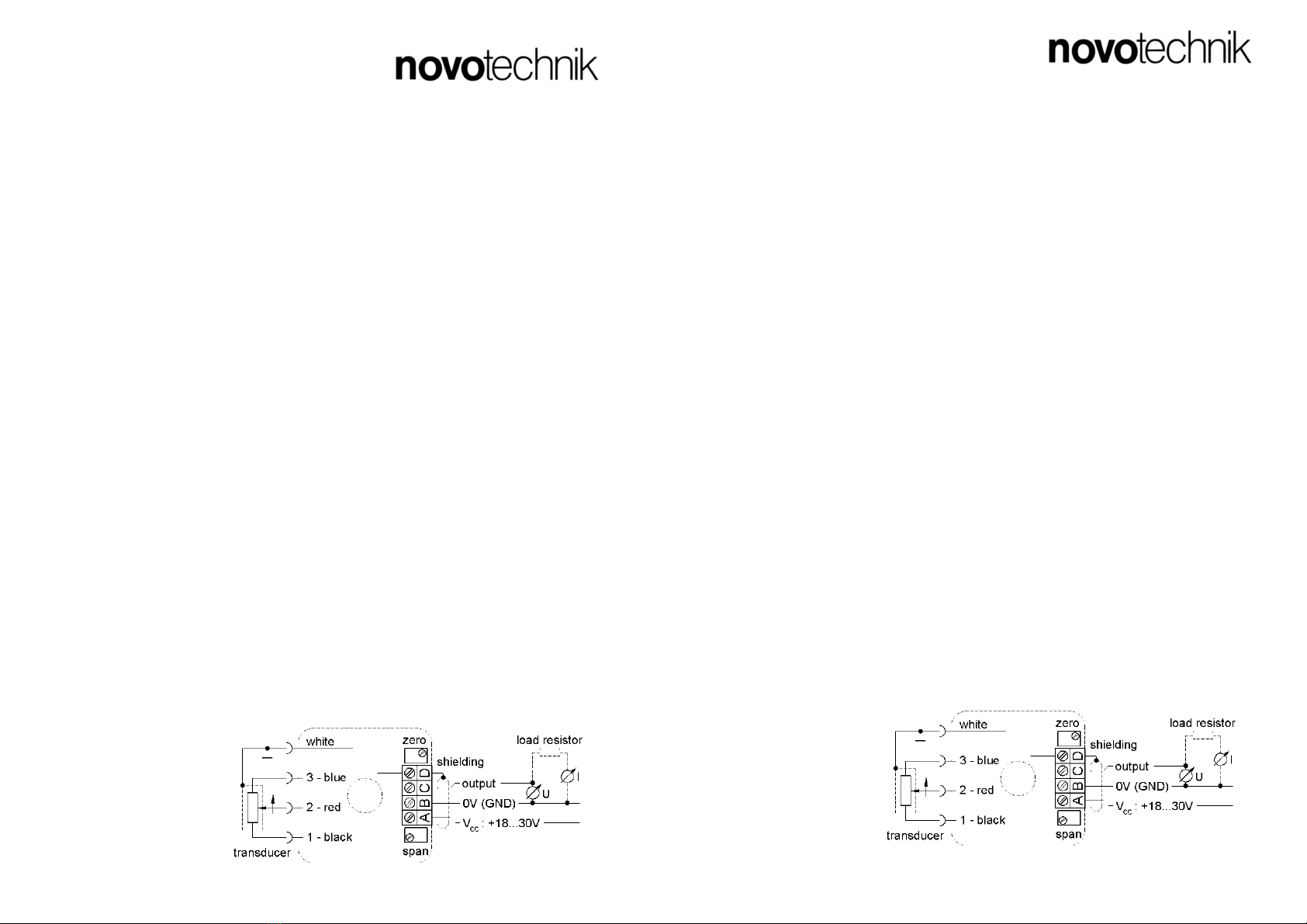
Anschluss-Schema:
Messwertumformer MUW
Anschlusshinweise
1. Vorbereitung des Anschlusskabels
Empfohlen wird ein 3- oder 4-adrig verdrilltes Kabel (0,25 mm²) mit Schirmgeflecht und einem
Außendurchmesser von 4 bis 10 mm. Schrauben Sie die Kunststoffschraube der PG–Verschraubung
von der Leitungsdose ab und schieben Sie sie mit der Unterlegscheibe und dem Stopfbuchseneinsatz
über das Kabelende. Entfernen Sie 30 mm der Kabelummantelung und isolieren Sie 5 mm der Litzen
ab, verdrillen Sie ggf. das Schirmgeflecht. Benutzen Sie Aderendhülsen (0,5 und 0,75 mm² für die
Schirmung). Bei 4-adrigem Kabel sind beide Massedrähte für Klemme B in eine gemeinsame
Aderendhülse zu quetschen. Schieben Sie den in der Dose liegenden Schrumpfschlauch über die
Schirmung.
2. Öffnen der Leitungsdose
Ziehen Sie die Befestigungsschraube bei geschlossenem Deckel vollständig aus der Leitungsdose
heraus; heben Sie den Deckel ab.
3. Anschließen des Kabels
Entfernen Sie die Zugentlastungslasche ( 2 Kreuzschlitzschrauben) im Innern der Dose. Führen Sie das
wie unter (1.) vorbereitete Kabel in die Kabeldose ein. Schließen Sie die Litzen entsprechend dem
Anschlussschema (siehe unten) an der Klemmleiste an. Schieben Sie das Kabel soweit vor, dass die
Kabelummantelung in den Bereich der Kabelzugentlastung kommt; montieren Sie die Zugentlastungs-
lasche (für Kabel Ø < 5 mm wenden). Schieben Sie den Stopfbuchseneinsatz und die Unterlegscheibe
in die Kabeldose und verschrauben Sie ihn dicht mit der Kunststoffschraube.
4. Drehen des Buchseneinsatzes
Falls erforderlich, können Sie die Orientierung des Kabels durch Drehen des Buchseneinsatzes
folgendermaßen ändern: öffnen Sie die Leitungsdose, wie unter (2.) beschrieben. Drücken Sie den
Buchseneinsatz durch die Bohrung in der Mitte der Platine nach unten. Drehen Sie den Buchseneinsatz
in die gewünschte Position. Achten Sie beim Einsetzen darauf, keine Litzen einzuklemmen. Der Einsatz
sitzt etwa 1mm vertieft in der Dose.
5. Befestigung der Leitungsdose am Messwertaufnehmer
Schließen Sie den Deckel der Leitungsdose und stecken Sie die Befestigungsschraube ein. Legen Sie
die beiliegende Dichtung auf den Stecker, stecken Sie die Leitungsdose auf und schrauben Sie sie mit
der Befestigungsschraube fest.
6. Vertauschen der Wirkrichtung
Soll die Zuordnung des Ausgangssignals zur Bewegungsrichtung des Aufnehmers geändert werden, so
ist folgendermaßen vorzugehen: Nehmen Sie den Buchseneinsatz wie unter (4.) beschrieben heraus.
Vertauschen Sie die Litzen 1 (schwarz) und 3 (blau) am Buchseneinsatz. Wiedermontage wie unter (4.)
beschrieben.
7. Justierung (nur MUW250)
Justieren Sie zunächst den Nullpunkt: Bewegen Sie dazu den Schleifer des Aufnehmers in die
Anfangsposition. Achten Sie unbedingt darauf, dass sich der Schleifer innerhalb des elektrischen
Messbereichs des Sensors befindet.
Bei den Typen MUW250-0 und MUW250-1 justieren Sie nun das Ausgangssignal durch Verstellen des
Trimmpotis neben der Klemme D auf 0 V. Drehen Sie nicht über 0 V hinaus. Bewegen Sie den Schleifer
des Aufnehmers in die Endposition. Achten Sie auch hier auf den elektrischen Bereich des Sensors.
Justieren nun das Ausgangssignal mit Hilfe des Trimmpotis neben der Klemme A auf 10 V.
Beim Typ MUW250-4 gehen Sie bitte folgendermaßen vor: Bewegen Sie den Schleifer des
Aufnehmers in die Anfangsposition. Justieren Sie das Ausgangssignal mit dem Trimmer neben der
Klemme D auf
0 mA. Bringen Sie dann den Schleifer in die Endposition. Justieren Sie jetzt den Strom mit dem
Trimmpoti neben der Klemme A auf 16 mA. Bewegen Sie den Schleifer in die Anfangsposition und
justieren Sie den Strom mit dem Trimmpoti neben Klemme D auf 4 mA. Überprüfen Sie den Wert in der
Endposition und wiederholen Sie ggf. diesen Vorgang.
Anschluss-Schema:
Dok.-Nr. MU00000122R1 (Nullpunkt und Bereich nur MUW250)
Dok.-Nr. MU00000122R1 (Nullpunkt und Bereich nur MUW250)