Prostat PBT-531 User manual

User Manual
PBT-531
SHIELDED BAG TEST KIT


PROSTAT® PBTͳ531 SHIELDED BAG TESTER
SecƟon Topic Page
I. Introducon 4
II. Components Included with the PBT-531 4
III. Assembly Instrucon for the PBF-520 Shielded Bag Fixture 5
IV. Pre-Test Setup 6
V. System Verificaon Test 7
VI. Shielding Bag Tesng 9
VII. Power Supply 12
VIII. Charging Baery 12
IX. Frequently Asked Quesons 12
X. Warranty 13
General Specificaons 13
Table of Contents
Copyright © 2019 by Prostat® Corporaon. All rights reserved. Printed in the United States of America. No part of this
manual may be used or reproduced in any manner whatsoever without wrien permission. For informaon contact
Prostat Corporaon.
Prostat is the registered trademark of Prostat® Corporaon
PicoScope and Pico Technology are registered trademarks of Pico Technology Ltd.
Tektronix is a registered trademark of Tektronix, Inc.

4Rev. B / August 20, 2019
PBT-531 Shielded Bag Test Kit
I. IntroducƟon
The Prostat PBT-531 is a mul-purpose portable tool that has a variety of uses:
• When used with the supplied PBF-520 Shielding Bag Test Fixture, a storage oscilloscope and a
computer the system can be used to test the discharge shielding properes of packaging materi-
als based on ANSI/ESD STM 11.31.
• The PDS-510 Discharge Simulator can perform two pin manual HBM tesng on ESD sensive
devices up to 4,000 volts. (See ANSI/ESDA/JEDEC JS-001 – Human Body Model Tesng).
• The PDS-510 comes with a precision DC power supply that can be used to charge conducve and
dissipave materials.
WARNING
As with any electrical device, use proper electrical precauons to avoid personnel shock.
Operang discharge simulators such as the PDS-510 HBM Discharge Simulator can result in
electromagnec interference (EMI). Individuals equipped with a heart pacemaker must not
operate the instrument or be in the vicinity while it is being used.
WARNING
Do not operate the PDS-510 with the cover removed. Internal voltages as high as 4,000 volts
are present when powered on. This could present a shock hazard to personnel.
WARNING
This equipment must not be operated in any environment where flammable gases or fumes
are present as this represents a safety hazard.
SERVICE
Do not aempt to service this PDS-510 yourself. Opening the covers of the unit may expose
you to high voltages and possible electric shock. If the unit requires service contact Prostat
for assistance. Opening the cover without authorizaon will void the warranty.
II. Components Included with the PBT-531
• PDS-510 HBM Discharge Simulator
• PBF-520 Shielded Bag Fixture
• Tektronix® CT1 Current Probe (Part of the discharge are assembly)
• PicoScope® Oscilloscope from Pico Technology®
• USB Drive with “Waveform Verificaon Setup“ and “Shielding Bag Test File” files for PicoScope
• Connecon and Grounding Accessories
• PRS-801-W Conducve Rubber Electrode
• PBT-500C Carrying Case
Note: Computer, Laptop or Tablet not included.
5
Rev. B / August 20, 2019
PBT-531 Shielded Bag Test Kit
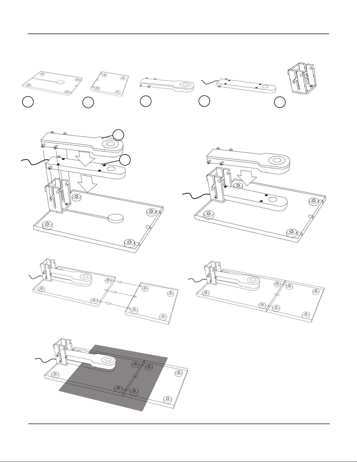
III. Assembly InstrucƟon for the PBF-520 Shielded Bag Fixture
Base Assembly Base Extension Bracket Assembly
Discharge Arm Capacitive Arm
ABCDE
1C
D
2
3
5
4

6Rev. B / August 20, 2019
PBT-531 Shielded Bag Test Kit
IV. Pre-Test Setup
A. Aach the supplied red test lead from the PDS-510’s red HBM Output to the red connector on the
Discharge Arm (C) of the PBF-520 fixture. (Figures 1 and 2).
B. Aach the supplied (short) green lead to the ground connector on the PDS-510 and the other end
to the ground connecon point on the Base Assembly (A) of the PBF-520 fixture.
Figure 1: Connect the short red lead to the HBM
Output connector on the PDS-510
Figure 2: Connect the other end of the red lead to
the Discharge Arm. Connect the short green lead
to the base assembly.
C. Aach a second (long) ground lead from the open PDS-510 ground connector to a known AC
ground using the Q007B Grounding Cube (Figures 3 and 4).
Figure 3: Connect the long green lead from the Figure 4: Connect the other end of the long green
ground lead to the Q007B of an outlet.
D. Connect the current probe coming from the Capacive Arm to the male end of the 50-ohm termi-
nator (Figure 5).

7
Rev. B / August 20, 2019
PBT-531 Shielded Bag Test Kit
E. Connect the female end of the 50-ohm terminator to Channel A of the PicoScope (Figure 6).
F. Connect the supplied USB cable from the PicoScope unit to a computer.
Figure 5: The 50 ohm terminator connects to the
current probe.
Figure 6: Connect the female end of the 50-ohm
terminator to Channel A of the PicoScope.
V. System VerificaƟon Test
A. Install the PicoScope soware onto the computer by downloading it from Pico’s website at hps://
www.picotech.com/downloads. Use the version that is closest to the model of your Pico Scope.
B. Insert the supplied USB Thumb Drive and copy the 3 files named “Waveform Verificaon Setup“,
“Shielding Bag Test File” and “Shielding Bag Test File with Manual Cursors” to your computer’s
desktop.
C. Launch the PicoScope soware. Note: It is recommended that you launch the Pico soware first
and then open the files from the thumb drive.
D. From the PicoScope soware, click on File > Open and select the “Waveform Verificaon Setup
file” from the desktop
E. Turn on the PDS-510 by sliding the Main Power switch to the ON posion on the side of the meter.
F. Switch the POWER to the ON posion.
G. Switch the RANGE to the HIGH posion.
H. Switch the HIGH VOLTAGE to the ON posion.
I. By using the knob, adjust the voltage to 1.00 (1,000 volts).
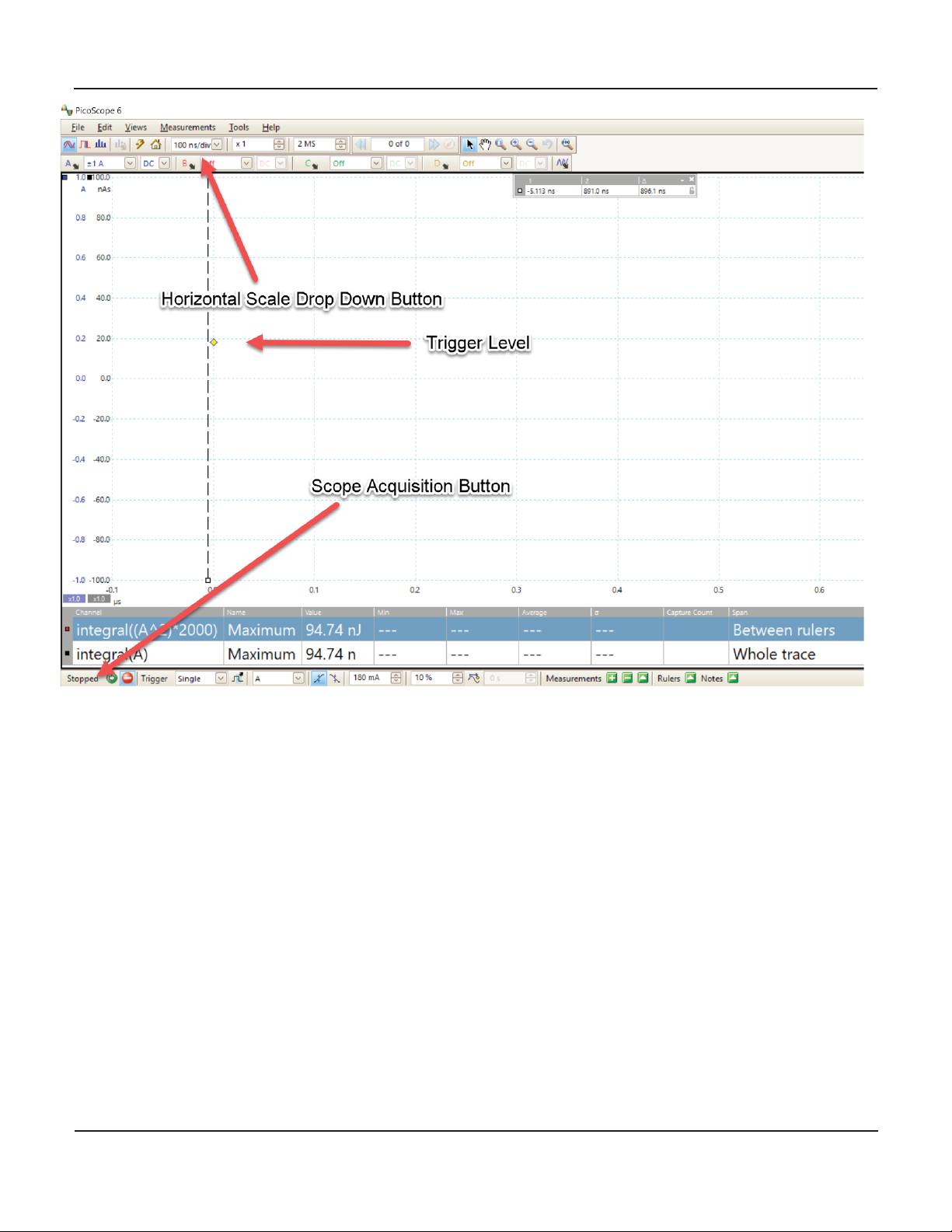
J. In the PicoScope soware, if needed, move the yellow trigger icon above the scope’s zero line
(0.2A) on the levercal scale (Figure 7).
K. Ensure that the scope horizontal scale is set to 100 ns per division (Figure 7).
L. Without inserng a shielded bag onto the fixture, set the Discharge Arm onto the Capacive Arm.
Set the 5 lbs Electrode on top of the Discharge Arm.
8Rev. B / August 20, 2019
PBT-531 Shielded Bag Test Kit
Figure 7: Screenshot of the PicoScope soŌware with the “Waveform VerificaƟon Setup file” open.
M. Click the “Stopped” buon at the boom lehand poron of the screen to place the scope in “ac-
quision” mode. The wording “Stopped” will change to “Running” (Figure 7).
N. Iniate a discharge by pressing the red DISCHARGE buon on the PDS-510. If a waveform is ac-
quired, the “Running” will change to “Stopped”.
O. Using the computer mouse drag the lescope cursor (vercal doed line) to the leof the dis-
charge waveform start and the right cursor to the point where the waveform decays to zero. The
calculated energy should be 50 ± 6 uJ (microjoules) and the peak current should be greater than 420
mA (milliamps 0.42 amps). The blue line is the discharge waveform and the red line is the calculated
energy curve in microjoules (Figure 8).
If the energy and/or the peak voltage are less than required, increase the voltage unl the required peak
voltage and energy levels are obtained. This voltage level might be in the 1030-1060 volt range.
Note: It is recommended that the discharge voltage be adjusted so that the energy is 50 ± 2 uJ. If there are
no values displayed in the red circle area move the right cursor slightly and the values should appear.

9
Rev. B / August 20, 2019
PBT-531 Shielded Bag Test Kit
Figure 8: Screenshot of the PicoScope soŌware measuring the energy.
VI. Shielding Bag TesƟng
The following test sequence describes the basic procedure as outlined in ANSI/ESD STM 11.31. The test is
designed for 20x25 cm (8x10 inch) stac shielding bags.
A. From the PicoScope soware, click on File > Open and select the “Shielding Bag Test File” or
“Shielding Bag Test File with Manual Cursors” file from the desktop.
NOTE
If you wish the soware to analyze the test automacally, use the “Shielding Bag Test
File”. If you wish to analyze the data manually, select the “Shielding Bag Test File with
Manual Cursors”.
B. Lithe Discharge Arm (C) and place it into the notch of the Bracket (E) (Figure 9).
Figure 9: The Discharge Arm siƫng up right
10 Rev. B / August 20, 2019
PBT-531 Shielded Bag Test Kit
C. Open the shielding bag to be tested and insert the Capacive Arm (D) into the bag (Figure 10).
Place the bag so the top of it lines up with the mark on the Capacive Arm (Figure 11).
Figure 10: The CapaciƟve Arm inside the shielded
bag.
Figure 11: The end mark on the CapaciƟve Arm
represents 10 cm (4”) from the top of the shielded
bag.
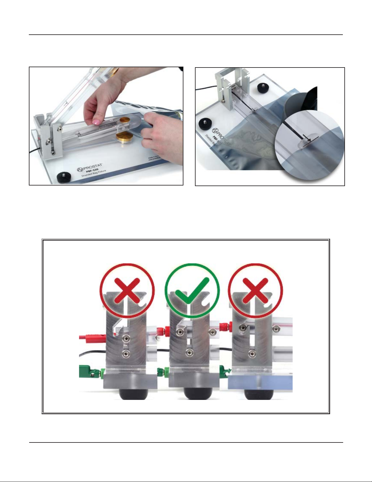
D. Move the Discharge Arm so that it contacts the top of surface of the bag.
NOTE
It is important that the Discharge Arm is properly aligned in the bracket notches.
Figure 12: The correct alignement
E. Place the PRS-801-W five lbs weight onto the Discharge Arm (Figure 13).
11
Rev. B / August 20, 2019
PBT-531 Shielded Bag Test Kit
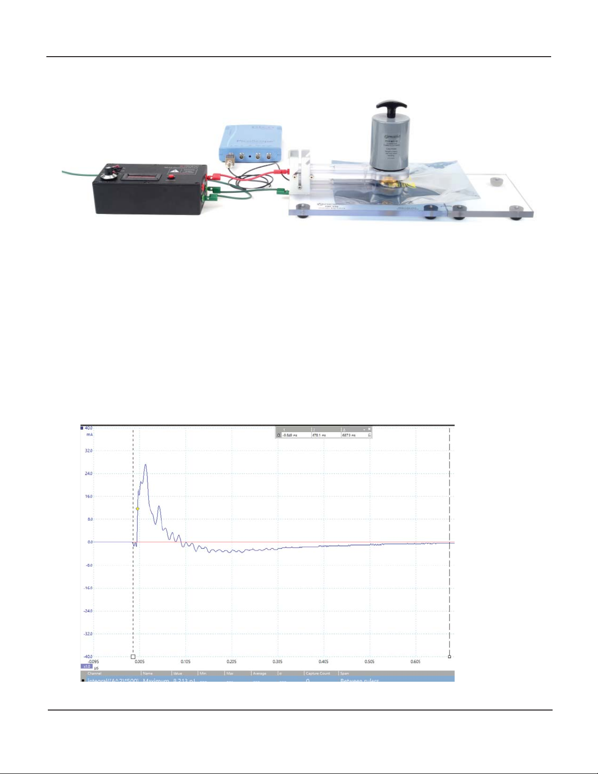
Figure 13: Complete setup for Shielded Bag Test.
F. Set the Range to HIGH on the PDS-510.
G. Turn the HIGH VOLTAGE to the ON posion.
H. Use the knob to set the voltage to the level established in System Verificaon Test.
I. Click the “Stopped” buon at the boom lehand poron of the screen to place the scope in “ac-
quision” mode. The wording “Stopped” will change to “Running” (Figure 7).
J. Iniate a discharge by pressing the red DISCHARGE buon on the PDS-510.
K. Using the mouse, drag the lescope cursor to the leof the discharge waveform and the right
cursor to the point where the waveform decays to zero. Note: If the waveform dips below the zero
line place the cursor at the point where it crosses the zero line form the second Ɵme (Figure 14).
Figure 14: Screenshot of the PicoScope soŌware measuring the energy.

12 Rev. B / August 20, 2019
PBT-531 Shielded Bag Test Kit
L. Record the calculated energy.
M. Repeat the process five more mes for a total of six discharges per bag.
N. Repeat the test for five more bags.
O. ANSI/ESD S11.31 requires that the discharge energy for stac shielding bags be less than 20 nJ.
WARNING
Turn offthe High Voltage when not in use.
VII.Power Supply
The PDS-510 is also equipped with a power supply that can be used to charge UNGROUNDED items from
0 to 4,000 volts. In order to use the power supply:
A. Make sure that the PDS-510 is connected to AC ground using one of the unit’s grounding ports.
B. Connect a cable to the Power Supply output port of the PDS-510.
C. Adjust the power supply’s voltage to the desired level.
D. Using the open end of the cable contact the cable to the item that requires charging.
E. Aer charging the item of interest, turn the PDS-510 offto prevent shocks and damage to the PDS-
510. Care must be exercised to prevent shocks to personnel.
VIII. Charging the BaƩery
The PDS-510 is supplied with a universal charger in order to charge the baery. In order for the baeries
to charge, make sure the Main Power switch is ON. The baeries will not charge if the Main Power is OFF.
The charger comes with several adapters for different outlets.
IX. Frequently Asked QuesƟons
A. PicoScope 6 does not recognize my device:
1. Verify that the LED light is lit on the front of the oscilloscope. There should be a red light.
2. Check the USB cable (ensure it is the supplied Pico blue USB cable). Try a different USB port.
3. If using a device with an external power supply, disconnect and reconnect the power supply.
4. If using a desktop PC, consider using the rear USB ports.
5. If using mulple USB devices on a PC and the PicoScope does not have an external power
supply, consider using a powered USB hub.
6. Device Manager – confirm that the device is listed either under Pico Technology Instruments
(or Universal Serial Bus controllers for older models such as the PicoScope 2205).
7. Confirm that the operang system is Windows XP (SP 3), Vista, 7, 8 or 10 (32 or 64-bit).
8. Verify that the .NET framework version is 2.0 (Windows XP) or 3.5 or later by going to the Add/
Remove Programs window in Control Panel and verifying which one is installed.
9. Ensure all the latest Windows updates have been applied to the PC.
10. Is the PC connected to the internet when installing or starng PicoScope 6?

13
Rev. B / August 20, 2019
PBT-531 Shielded Bag Test Kit
X. Warranty
Prostat Warranty
Prostat Corporaon expressly warrants that for a period of one (1) year from the date of purchase, that
Prostat instruments will be free from defects in material (parts) and workmanship (labor). If PROSTAT re-
ceives noce of such defect during the warranty period, Prostat will replace at its expense such parts that
it determines to be defecve. Any defecve part must be returned to PROSTAT postage prepaid with proof
of purchase date.
Warranty Exclusions – THE FOREGOING EXPRESS WARRANTY IS MADE IN LIEU OF ALL OTHER PRODUCT
WARRANTIES, EXPRESS AND IMPLIED, INCLUDING MERCHANTABILITY AND FITNESS FOR A PARTICULAR
PURPOSE, WHICH ARE SPECIFICALLY DISCLAIMED. The express warranty will not apply to defects or dam-
age due to accidents, neglect, misuse, alteraons, operator error, or failure to properly maintain, clean, or
repair products. Limit of Liability – in no event will Prostat or any seller be responsible or liable for special,
incidental, or consequenal losses or damages, under any legal theory including but not limited to con-
tract, negligence, or strict liability.
Fulfillment by Prostat of its express warranty obligaons described above will be purchaser’s exclusive
remedy and will be Prostat’s and seller’s limit of liability for any breach of warranty or otherwise.
PDS-510 HBM Discharge Simulator SpecificaƟons
Discharge Output: Adjustable up to 4kV
Power Supply Output: Adjustable up to 4kV
Power Supply Accuracy: ±2%
Discharge Waveform
ANSI/ESD STM11.31: Rise me @ 0Ω: <10 nsec
@ 500Ω: <20 nsec
Fall me @ 0Ω: 150±15 nsec
@ 500Ω: 200±20 nsec
Ringing: <15%
Power: Baeries: 4 each AA 2600 mAh low self-discharge, Rechargeable, Nickel-
Metal Hydride Baery
Power Supply: From 90VAC to 264VAC, 47Hz to 63Hz. UL and TUV 60950-1
approved.
Dimensions: 7.5”L x 4.5”W x 2.5”H (19.05cm x 11.43cm x 6.35cm)
Weight: 2.0 lbs (907g)
PBF-520 Shielded Bag Fixture SpecificaƟons
Base Material: Flame Retardant Polycarbonate
Surface Resisvity: >1x10¹³Ω

14 Rev. B / August 20, 2019
PBT-531 Shielded Bag Test Kit
Discharge and Ground
Electrodes” 1.5” (3.8 cm) brass, gold plated
Capacive Probe: 0.830” (2.1 cm) brass, gold plated
Capacitance: Nominal 8pF
High Voltage Resistor: 500 Ohms, 1% tolerance
Support Area Surrounding
the Ground Electrode: 8x10” (20x25cm) - without Base Extension aƩached
8x15” (20x35cm) - with Base Extension aƩached
Dimensions: 11”L x 8”W x 4”H - without Base Extension
6”L x 8”W x 1”H - Base Extension
Weight: 3.0 lbs (48 oz) - without Base Extension
1.0 lbs (16 oz) - Base Extension
Tektronix® CT1 Current Probe - Includes AƩenuator
Bandwidth: 1 GHz
Sensivity (into 50Ω): 5mV/mA
Accuracy: ±3%
Cable Length: 40” (1 meter)
PicoScope® Oscilloscope SpecificaƟons
Bandwidth: 200 MHz
Sampling Rate: Up to 1 GS per seconds
PC Connecvity: USB 2.0 (USB 3.0 compable). USB cable included
Power Requirements: Powered from USB port
Soware Included: PicoScope 6 for MicrosoWindows 7, 8 and 10; 32-bit and 64-bit

15
Rev. B / August 20, 2019
PBT-531 Shielded Bag Test Kit

PROFESSIONAL STATIC CONTROL PRODUCTS
630-238-8883 • Fax: 630-238-9717 • 1-855-STATIC1 • www.prostatcorp.com
Prostat Corporaon
Specificaons are subject to change without noce.
All Prostat trademarks and trade names are the property of Prostat Corporaon.
All other trademarks and trade names are the property of their respecve companies.
Other manuals for PBT-531
1
Table of contents
Other Prostat Test Equipment manuals


