PROTEA BG 760 Guide

B.G. 760 (30”) PETROL Cylinder Mower
Operating Instructions
&
Spare Parts Manual

1
Ref. No.: CK 91/04496/23 Vat No.: 4830119907
Tel: 011 828 9935
Mobile: 082 458 7257
Email: [email protected]
Email: sean@proturf.co.za
For further information on any Protea products, please visit our website www.proteamachines.com
Postal Address
Germiston
Gauteng
South Africa
Manufacturers of Protea Range of Mowers, Sodcutters, Scarifiers
PROTEA TURF EQUIPMENT cc
Physical Address
BEDFORDVIEW
SOUTH AFRICA
32 Shaft Road
CONTACT DETAILS:
P.O.BOX 1673
Knights
2008 GAUTENG

1Know your controls. Read the owner's manual 13 Stop the engine whenever you leave the
carefully. Learn how to stop engine quickly in an mower, even for a moment.
emergency. 14 Stop the engine before pushing mower
2Make sure the lawn is clear of sticks, stones, across gravel drives, walks or roads.
bones, wire and debris. They could be thrown
by the blade. 15 Do not allow children or people
unfamiliar with these instructions to use
3Stop the engine and disconnect spark plug wire the mower.
before checking or working on the mower. 16 On slopes or wet grass, be extra careful of
4Before using, always visually inspect to see that your footing.
blade bolts and cutter assembly are not worn or
damaged. Replace worn or damaged blades 17 Never cut grass by pulling the mower towards
bolts in sets to preserve balance. you.
Damaged blades and worn bolts are a
major hazard. 18 Never use an electrically powered mower in
the rain or when grass is wet.
5Check all nuts, bolts and screws often, always
be sure the mower is in safe operating 19 Be extremely careful when using a ride on
condition. Use only replacement parts made
mower on slopes.
and guaranteed by the original manufacturer
of your mower 20 Never leave wind-up starters in a wound
condition.
6
Add fuel BEFORE starting engine. Avoid spilling
petrol and do not fill the tank while the engine is 21 Do not over speed the engine or alter governor
running or while you are smoking. settings. Excessive speed is dangerous
and shortens mower life.
7Do not mow whilst people, especially children
or pets are in the mowing area. 22 It is advisable to wear suitable eye protection
when operating a mower.
8Never use the mower unless the grass catcher ,
or guards provided by the manufacturer, 23 Turn the fuel off at the conclusion of mowing
are in position. and reduce the throttle setting during
engine run-ou.
9Do not mow barefoot or in open sandals.
Wear long trousers and heavy shoes. 24 Store fuel in a cool place in a container
specifically designed for the purpose. In
10 Disengage all blade and drive clutches before general, plastic containers are unsuitable.
starting.
25 Never pick up or carry a mower when it is
11 Start the engine carefully with feet well away operating.
from the blades.
12 Do not operate engine in a confined space where
exhaust fumes (carbon monoxide) can collect.
POWER LAWNMOWER SAFETY PRECAUTIONS
i
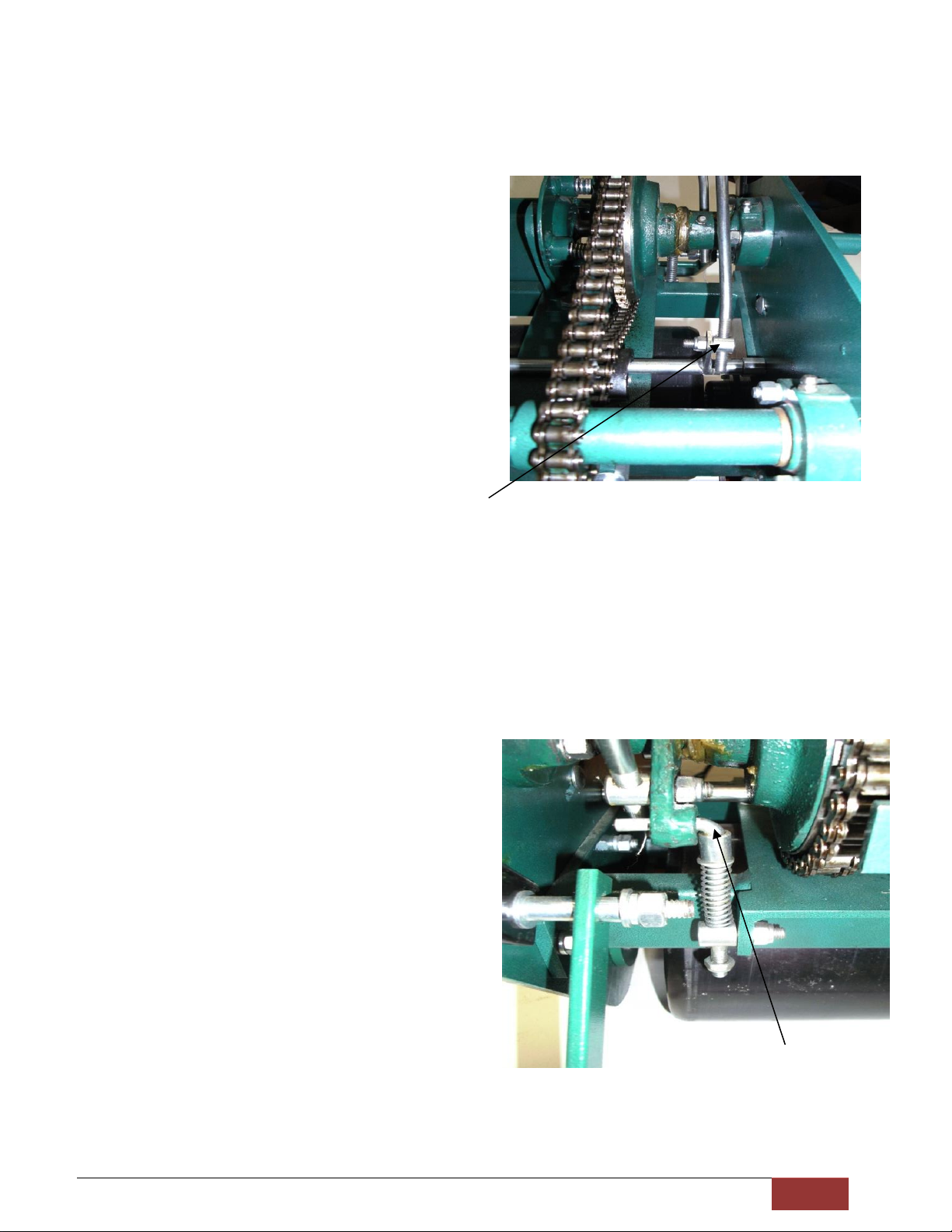
TO ASSEMBLE THE BELT OPERATING CLUTCH ROD
NOTE: The positions of the screwed adjusters on the clutch rods are only to make the levers operate
correctly and once they are assembled, they should NOT be altered. These adjustments are NOT used
to alter the belt or traction clutch tensions.
Remove top Guard. The screwed adjuster (1) has
been
positioned and set on the road at the correct
position and
must enter the hole in the lug from the outer side of
the lug.
(Nearest side to the side frame of the mower) See
Fig.4
FIG.4
Enter the adjuster into the lug and screw on the “nyloc” lock nut to retain the adjuster. Tighten the
nut and then unscrew it about ¼ of a turn to make sure that the adjuster is free to pivot into the hole
in the lug. The clutch lever should now snap back and hold into position when the belt clutch is
engaged by moving the clutch lever back towards the handle bar.
TO ASSEMBLE THE TRACTION CLUTCH ROD
The screwed adjuster has been positioned and set on the (1) rod at the correct position and it must enter the
hole in the ramp arm from the outer side of the lug.
(Nearest side to the side frame of the mower) See Fig. 5
Enter the adjuster into the hole and screw on the “nyloc”
nut to retain the adjuster (The lever can be relaxed while
doing this). Tighten the nut and then unscrew it about ¼
turn to make sure that the adjuster is free to pivot in the
hole in the arm. The clutch lever should now snap back
and hold into position when the traction clutch is engaged
by moving the clutch lever back towards the handle bar.
Fig.5
NOTE: If either the belt operating clutch rod or the traction clutch rod does not snap back firmly one
additional turn of the adjuster up the clutch rod may be necessary.
1
1

ii
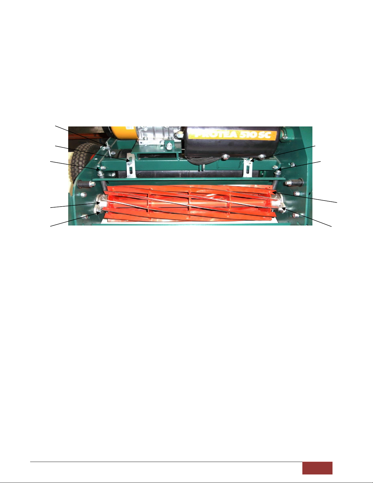
CUTTING ADJUSTMENTS
FRONT ROLLER:
The height of the cut of the mower is controlled by the adjustment of the front roller.
The mower cuts lower if the front roller is raised, or alternatively the mower cuts higher if the front roller is
lowered.
HEIGHT ADJUSTMENT:
Adjust the front roller position by loosening the clamping bolts (1)Fig.6 and the moving roller to the required
setting by loosening and locking nuts (A), and then Retightening the bolts (1). Indicator marks are provided at
both sides to facilitate even setting. This can be visually checked very quickly by laying the mower back on the
handles (turn off petrol tap first) and “sighting” that the front roller setting is parallel with the roller drum. For
very accurate setting of “supercut” models, a setting gauge must be used. (See “Setting Gauge” instructions).
FIG.6
FRONT ROLLER SCRAPER:
The scraper is self-adjustable and does not require constant adjustment. If the scraper material has become so
worn that it is no longer making contact with the front roller, some slight adjustment may be required. In
order to adjust the scraper, loosen the grub screws found within the Front Roller Adjuster Bracket (2) Fig.6 and
readjust the scraper bar so that it is making contact with the entire length of the front roller and ensuring that
the scraper can swivel freely before once again locking the grub screws.
15
7
5
1
A
2

iii
TEASING RAKE ADJUSTMENT
FIG.13
In order to adjust the teasing rake, loosen the locknut (2)Fig.13 and use the Teasing Rake Stud Nuts (1)Fig.13 in
order to achieve the desired height. Before once again tightening the locknuts, ensure that the teasing brush is
as level as possible.
SETTING GAUGE
FIG.7 FIG.8
This illustrates the method of setting the gauge. Coins are commonly used standard to gauge the screw
adjustment –See Fig.7.
The distance between the setting gauge bar and the underside of the adjustable screw head represents height
of cut. Lock the screw in the desired position with the wing nut. To use the setting gauge, rest it against the
1
2
iv
underside of the front and rear rollers, as illustrated, Fig.8, and by adjusting the front roller, the desired height
of cut will be obtained when the underside of the screw head lightly touches the top cutting edge of the
bottom blade when checked at locations across the width of the blade. Take care not to force the head of the
adjusting screw onto the bottom blade, as this could distort the blade and affect the setting. In conjunction
with setting the height of cut, refer to section “to check the mower for alignment”.
DEFLECTOR:
For cutting some grasses, the deflection into the grassbox can be improved by altering the deflector. To adjust,
slightly loosen the adjustment set screws (4)Fig.9, and by moving the deflector plate upwards, the grass throw
will be higher and longer, or downwards and the grass flow will be lower and shorter. After adjustment
retighten the screws.
Fig.9
CUTTER:
The bottom blade is fixed and adjustment for wear or other reasons is confined to the cutter.
To adjust the cutter loosen the clamping bolts (5)Fig.9, at each side. Turn adjusting nuts (6)Fig.9, clockwise to
lower the cutter on to the bottom blade. Retighten the two clamping bolts.
The cutter should be adjusted to bear lightly on the bottom blade along its full width. If the cutter rubs harshly
on the bottom blade there will be excessive wear of both cutter blades and bottom blade, and an
unnecessarily heavy load on the power unit. Excessive wear is also experienced if cutter is left running dry, i.e.
not cutting grass.
B
15
7
4
6
B
5
5
6
4

v
REVERSING CUTTER:
In time the cutting edge of the cutter cylinder becomes dull and a feature of this machine is that the cutter may
be easily removed as described above, reversed end for end and replaced. This provides a new keen cutting
edge. If the bottom blade is badly worn, this should be replaced at the same time.
To replace the cutter/soleplate assy. To the machine place the assembly directly below its final position and
lower the machine onto the assembly. The holes for the screws are then easily lined up.
CUTTER / SOLE PLATE ASSY
The cutter and sole plate is one assembly and can only be removed as one unit.
1. Remove the deflector by unscrewing the adjustment set screws (4)Fig.9. pull the deflector
upwards and forward. Spring clips are holding the bottom end to the sole plate.
2. Remove the chain cover (3 screws)
3. Remove cutter chain
4. Remove cutter sprocket. Note, Left-Hand thread.
5. Finally remove the cutter clamping bolt (5)Fig.6, and the two sole plate bolts (7)Fig.6, at each side
of the machine.
The whole assembly of cutter and sole plate/bottom blade is then free to drop out of the machine.
To remove the cutter from the above assembly the following procedure is to be used: SeeFig.10
1. Remove the Cutter Bearing Housing Pivot Screws (8) (5/16 A/F Allen Key).
2. Remove cutter adjusting nuts, washers and spacer tubes (9).
3. Cutter is now free from sole plate assembly.
4. Remove Bearing Housings (10) from cutter.
5. Remove R.H. Bearing Nut. Note, Left-Hand thread.
6. Reassemble by reversing the procedure.
Fig.10
9
9
10
8

vi
CHAIN TRANSMISSION
The three chains, countershaft to drum clutch sprocket (11) Fig.11, countershaft to cutter (12) Fig.12, and
drum clutch to drum (13) Fig.12 are all provided with chain adjusters (14). The chains should never be adjusted
tightly. It is advisable to leave slightly more slackness on the cutter chain to allow for cutter adjustment
without having to adjust the chain.
NOTE: There are 2 holes for locating the cutter chain adjuster, should additional adjustment become
necessary.
DRUM AND COMPONENTS
The drums are manufactured from steel tube with welded ends. On the right hand side frame of the machine
(15)Fig.6, provision is made to adjust the drum into the alignment with the bottom blade.
To check and adjust the drum lay the machine back on its handle with the drum on an even surface. From a
front centre position of the machine, line up by eye, the underside of the front roller and the cutting edge of
the bottom blade. If they are parallel, adjust one end of the front roller. Now by eye, check the front roller
with the drum if out of alignment, loosen lightly the drum bearing housing bolts. Adjust to a parallel position
by the adjuster (15)Fig.6, and re-tighten the bolts and adjustment nuts.
11
Fig.12
C
14
14
12
13
14
Fig.11
14
13

vii
TO CHECK MOWER FOR ALIGNMENT
Lay the mower back on the handle.
Chalk the thin front end of the bottom blade about 6” of it’s length at both ends.
With the front roller remaining in approximately it’s normal height setting, “sight” the bottom of the front roller relative
to the chalked cutting edge of the blade. Adjust the front roller into exact alignment with the cutting edge, continually
sighting while adjustment proceeds. Lock the roller and re-check. Now use your height setting bar as an aligning tool by
placing the bar against the front roller and the rear roller on the extreme LEFT HAND SIDE (Chain Cover Side).
Adjust the setting bar screw so that it just contacts the bottom blade cutting edge. Test the right hand side of the rollers
with the same setting, and adjust the rear roller up or down until the same screw contact is achieved on the blade.
As the movement of the rear drum could affect the original L.H.S setting slightly, reset the screw at the L.H.S. and recheck
the R.H.S. All elements of your machine will be in perfect alignment.
After tightening all adjustments a final check should be made.
The required height of the cut can now be checked and set in the normal manner. Refer section on “setting gauge”.
While the procedure may seem complicated it is in fact very simple to perform and can be carried out in less than 15
minutes. The sighting is easy and accurate because it is done from the front roller which is nearest to the operator. A
machine that is “true” will pay dividends by precision cutting of your green.
TO ADJUST THE DRUM CLUTCH (SEE FIG.15)
NOTE: The chain drive to the clutch must not be over tensioned; the chain adjuster should be set to allow
some slackness.
To ensure that the clutch does not slip there must be approximately 1mm clearance between the
thrust washer (15) and the operating ramp face (16) when the clutch is engaged. (Clutch lever
downward).
(SEE FEELERGAUGE)
To adjust, loosen the bearing housing bolts (17) and rotate housing slightly until the correct clearance
is obtained.
Fig.15
15
17
16
D
E
viii
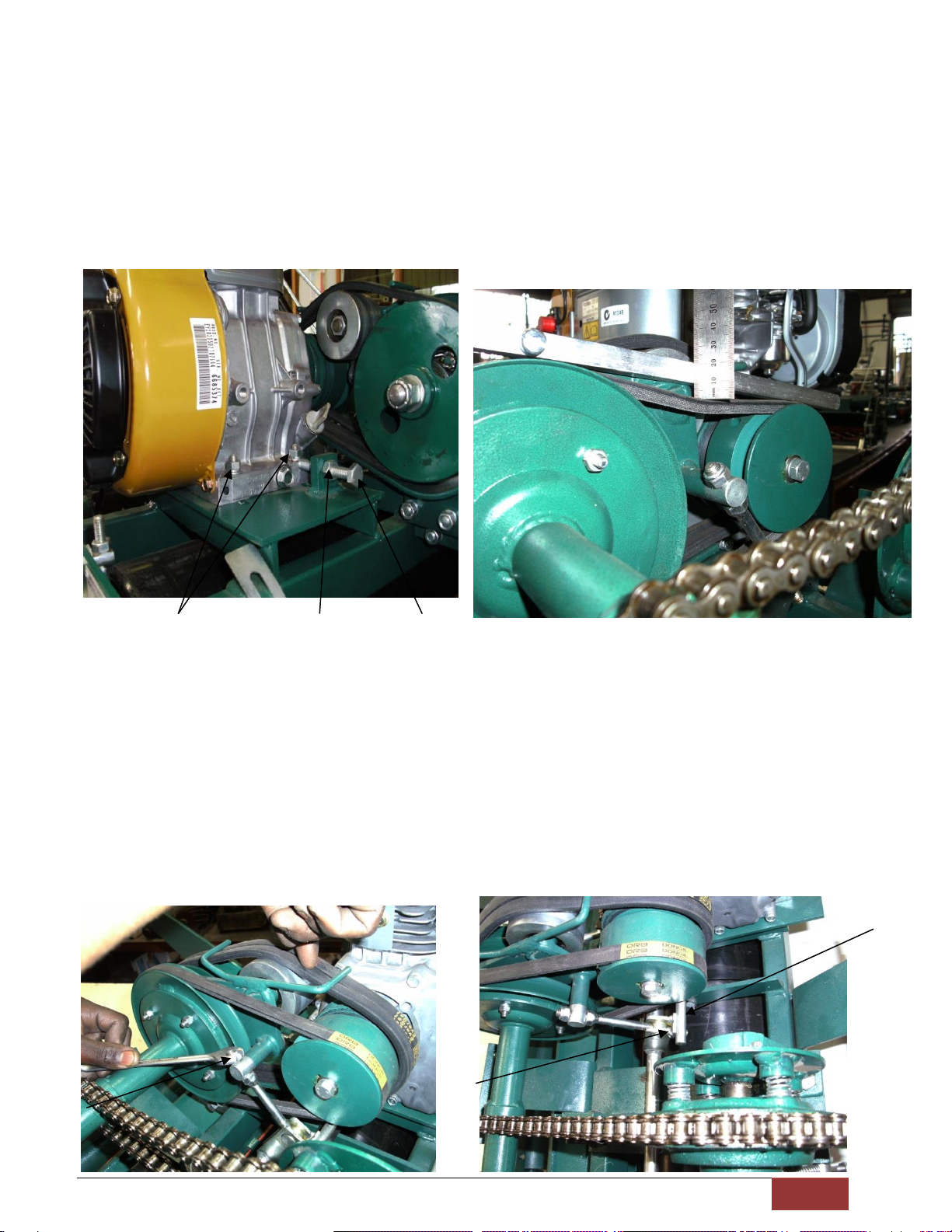
ADJUSTING BELT TENSION
TO ADJUST TENSION OF SINGLE PULLEY BELT.
a) Slacken engine mounting bolts. (18) Fig.16
b) Tension belt by using engine adjusting screw. (19) Fig.16.
c) Check engine for squareness on table for pulley alignment before tightening engine bolts.
d) DO NOT OVERTENSION –allow belt to depress 10mm (3/8”) from straight edge placed along top of
belt. See Fig.17.
e) Ensure engine adjusting screw locknut (20) is tightened after adjustment.
Fig.16
Fig.17
TO ADJUST TENSION OF TWIN BELTS
These belts drive the cutter and should be tight enough for satisfactory cutting without slip.
Tension belts by screwing jockey pulley adjuster upwards (anti-clockwise) from its trunnion –tighten nyloc nut
when set. (21) Fig.18.
When correctly set the tensioning mechanism should lock over centre with only light pressure, otherwise the
belts will be over tight, which will strain the jockey pulley assembly.
NOTE:The backstop (22) Fig.19, that limits the “off” or “slack” position of the belt adjusting mechanism
causes the cutter clutch lever to snap back into disengaged position when operated. If this clutch lever
does not hold into position the backstop should be pivoted upwards and securely retightened.
Fig.18
Fig.19
18
20
19
21
H
22

ix
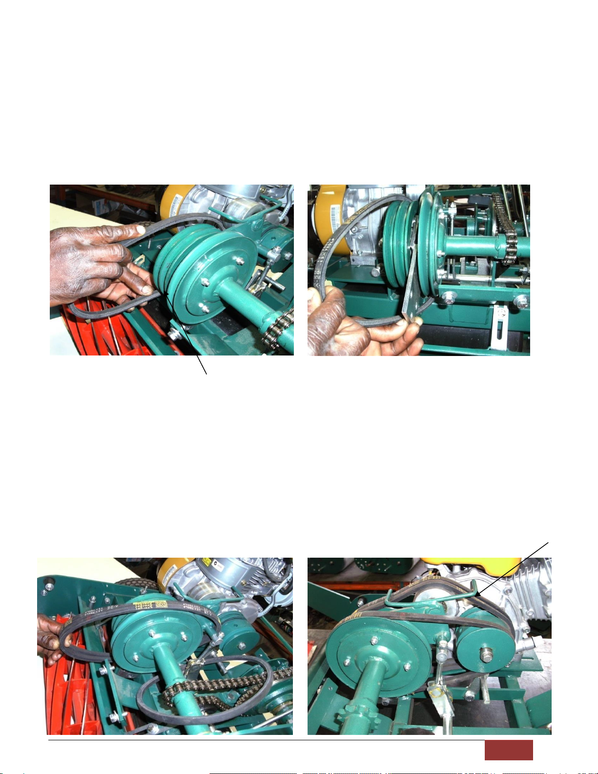
REPLACEMENT OF BELTS
TO REMOVE BELTS
The replacement of belts is quite easy and can be performed in less than 15 minutes. All belts are identical.
Cutter drive Twin belts should be matched for length and MUST always be replaced as a PAIR, and it is good
maintenance to replace the traction drive belt at the same time.
CUTTER DRIVE BELT
1. Remove the deflector plate. See Fig.9
2. Remove belt limiter (23) Fig.20
3. Back off engine adjusting screw (24) fully.
4. Slack off engine mounting bolts.
5. Move cutter clutch lever (25) forward, Fig.21
6. Slide engine forward.
7. Lift twin belts off large pulley.
8. Move traction belt (single) sideways off engine pulley.
9. Move twin belts sideways off engine pulley. Fig.22
10. Push motor right back
11. Withdraw twin belts through opening between jockey and engine pulley. Fig. 23
Fig.20 Fig.21
24
23
25
J
G
F
Fig.
22
Fig. 23
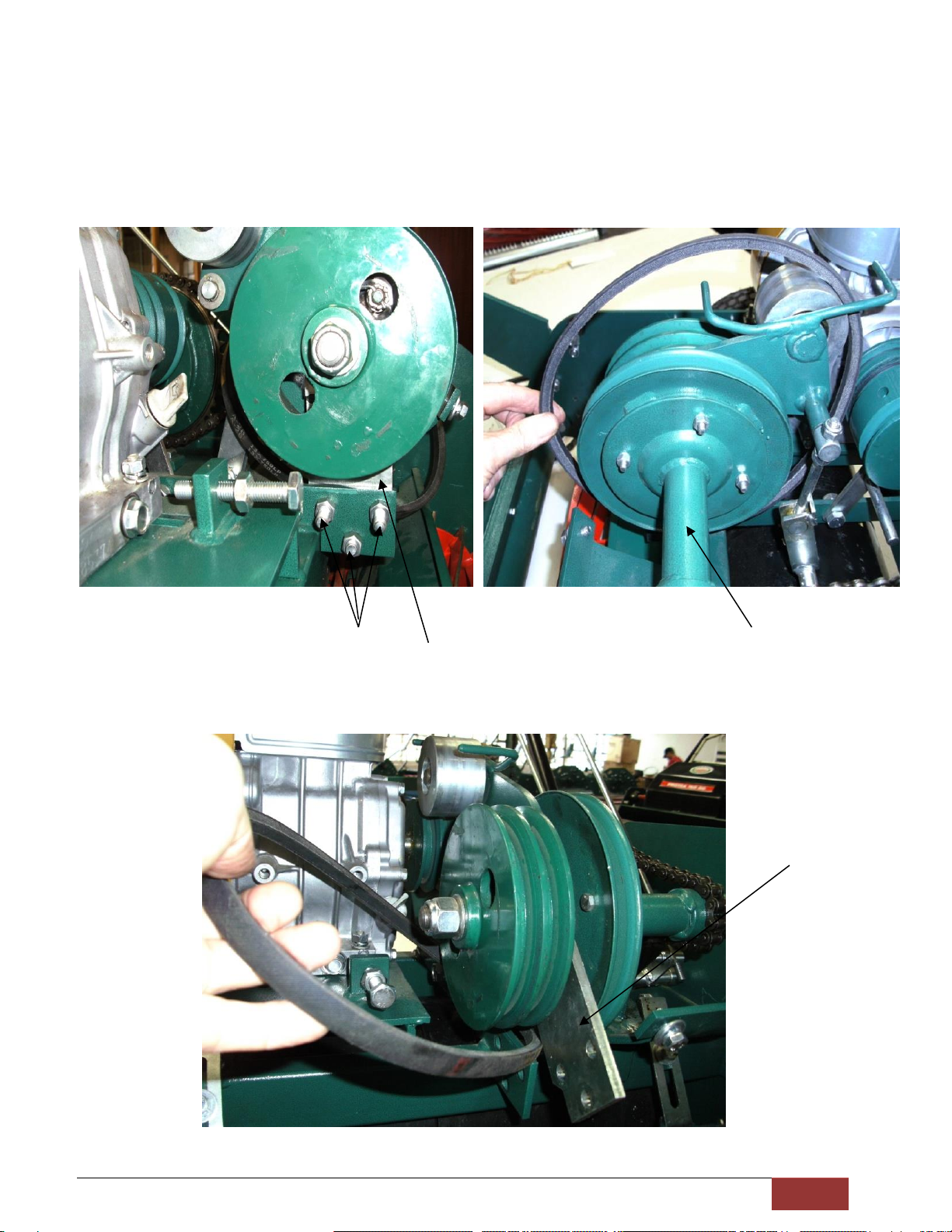
x
TRACTION BELT DRIVE
1. Remove the three bolts (26) to replace the jockey pulley pivot plate (27). See Fig.24.
Note: Washers must return to the same position on re-assembly.
2. With draw belt through opening between jockey and engine pulleys. See Fig.25.
3. Pull belt forward. Pivot plate will swing forward and belt will come clear. See Fig.26.
Fig.24 Fig.25
Fig.26
26
27
K
27
xi
TO REPLACE BELTS
TRACTION DRIVE BELT
NOTE:The gap between the jockey and engine pulleys can be manipulated by moving the pivot plate (27)
while locating the belt.
1. Insert belt through gap between jockey and engine pulleys. See Fig.27.
2. Swing jockey pulley pivot plate forward and feed belt through gap (under pivot plate) See Fig.28.
3. Replace pivot plate bolts (NOTE: position of washers)
Do not put belt on engine pulley until twin belts are installed.
Fig.27
CUTTER DRIVE BELTS
1. Feed twin belts through gap between jockey and engine pulley. See Fig.29.
2. Slide Engine forward.
3. Locate twin belts in engine pulley groove.
4. Position twin belts under guide fingers (28) and onto large pulley.
5. Position single belt on pulleys. See.Fig.30.
6. Move cutter clutch lever (25) back towards handle. See Fig.21.
7. Push engine back and the tension single traction belt by engine adjusting screw and tighten engine
mounting bolts.
Do not over tighten belt –allow belt to depress 10mm (⅜”) from straight.
8. Replace belt limiter (23)Fig.20, ensuring both belts are seated in pulley grooves and adjust tension of
twin belts. Refer to section “to adjust tension of twin belts.”
Fig.30
27
28
Fig 28
Fig.29
xii
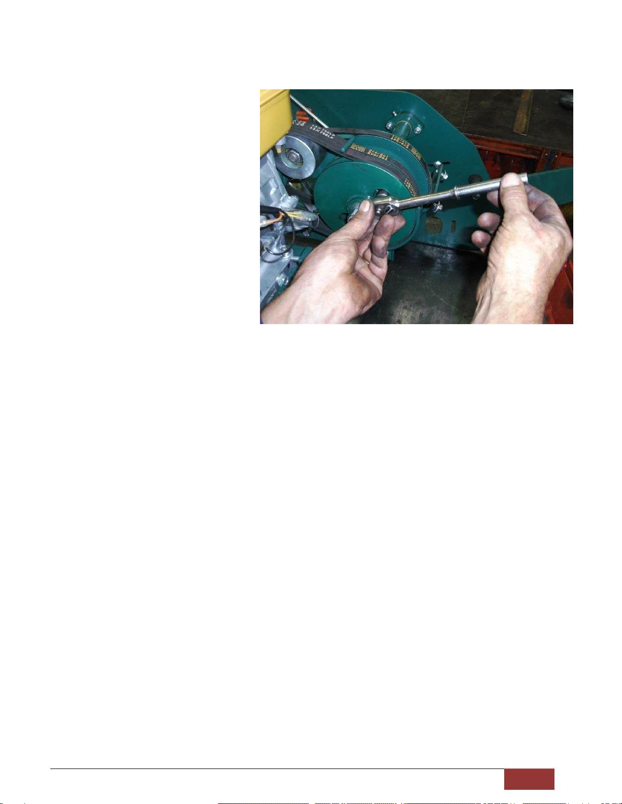
TO ADJUST JOCKEY PULLEY ARM
Should the pivot arm require adjustment
to eliminate sideways movement,
tighten pivot nut with13mm A/F socket
and then unscrew it about ¼ of a turn to
make sure the pivot arm is just free to
pivot.
Fig.31

xiii
GREASE AND OIL LUBRICATION
THE FOLLOWING POINTS REQUIRE GREASE LUBRICATION:-
1. Cutter bearings. ‘b’ fig.9.
2. Counter shaft bearing housing at side frame end only. ‘c’ fig.11.
3. Drum clutch bearing housing, both ends. ‘d’ fig.15.
THE FOLLOWING POINTS REQUIRE OIL LUBRICATION:-
1. Drum clutch ramp ‘e’ fig.15.
2. Drum clutch plate, do not use excessive amount of oil, 2 or 3 drops of oil in hole every 3 months. (to
keep the lubricating strip supplied) ‘f’ fig.22.
3. Jockey lift/pivot pin ‘g’ fig.22.
4. Pivot tube both ends ‘h’ fig.19
5. Lightly oil chains –particular attention to the clutch sprocket chain –avoid any excess oil on large
sprocket.
6. Cutter and clutch levers ‘j’ fig.21.
7. Drive TUBE ‘K’ FIG.25.

SPARE PARTS
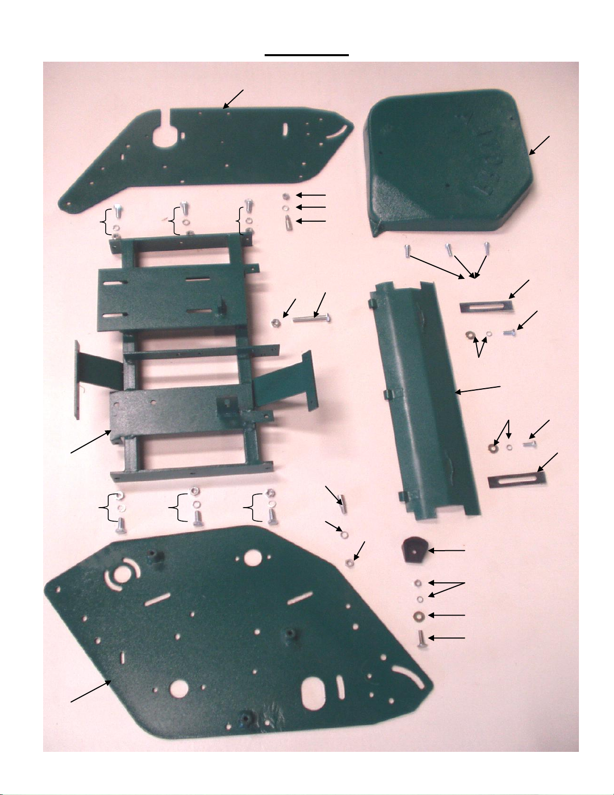
FIGURE 1
17
6
3
4
5
2
7
15
14
13
7
7
7
7
7
7
9
16
13
14
15
18
10
12
11
8
1
5
4
3

ILLUS
NO.
1HD760 (30") INNER FRAME ASSY (760 mm)
2HD760 (30") DEFLECTOR ASSY (760 mm)
3DEFLECTOR ADJUSTER BAR
4HEX. SET SCREW M8 x 20
5M8 FLAT WASHER & SPRING WASHER
6CHAIN COVER CASE H.D.
7
8SET SCREW M10 x 25
9
10 CHAIN ADJUSTER
11 M10 BRIGHT WASHER
12 NYLOC NUT M10
13
14 M10 SHAKERPROOF WASHER
15 HEX NUT M10
16 HEX SETSCREW M10 x 70
17 RH SIDE PLATE
18 LH SIDE PLATE
19 PURCHASE BLOCK (NOT SHOWN)
20 3/8 UNF NUT (NOT SHOWN)
21 M10 S/PROFF WASHER (NOT SHOWN)
DESCRIPTION
PART NO
651330
655605
305656
STD
STD
REFER FIG. 1
SCREW M8 x 20
M10 NUT
GRASSBOX ATTACHMNET PIN
656608
STD
STD
STD
455769
STD
STD
652594
STD
STD
STD
STD
659601
659600
301727
STD
Page 1
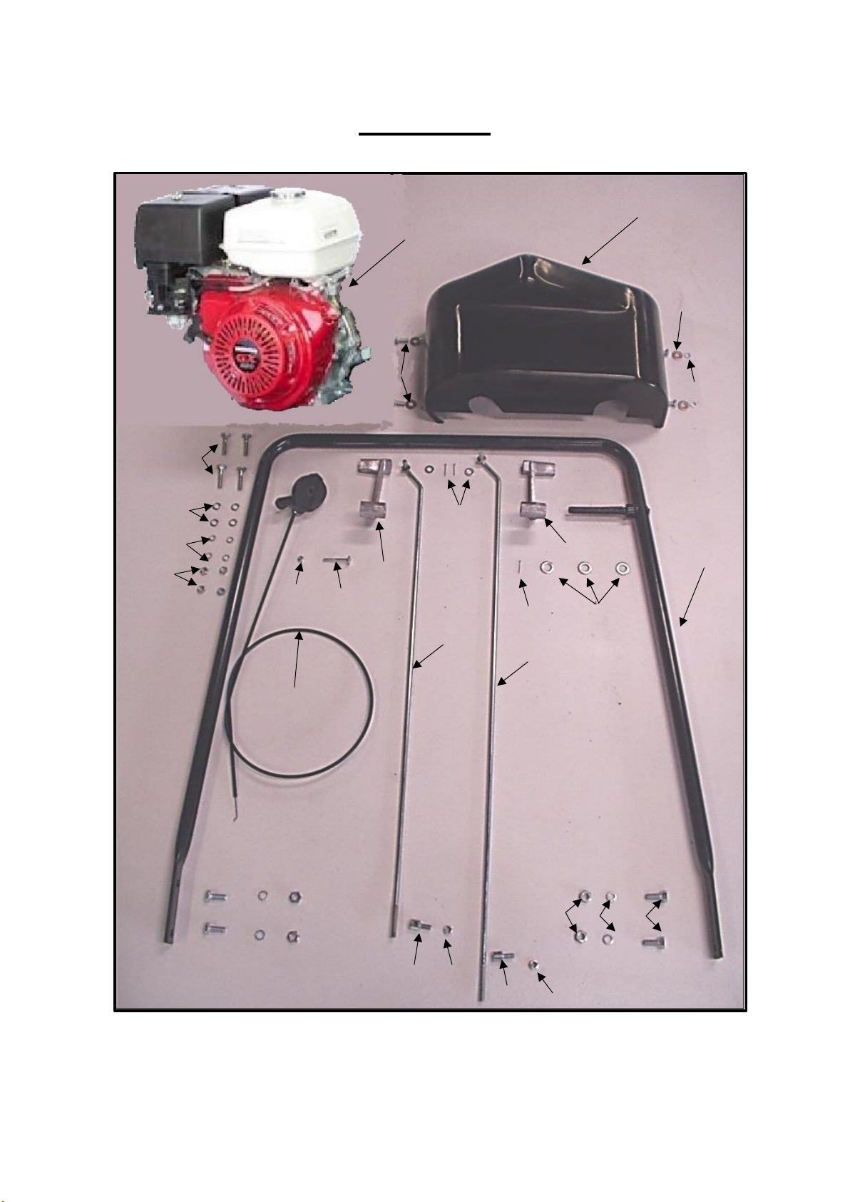
FIGURE 2
1
2
3
4
5
6
7
8
9
10
12
12
13
13
14
15
16
17
18
19
21
22
23
24
25
26
27
Other manuals for BG 760
2
Table of contents
Other PROTEA Lawn Mower manuals


