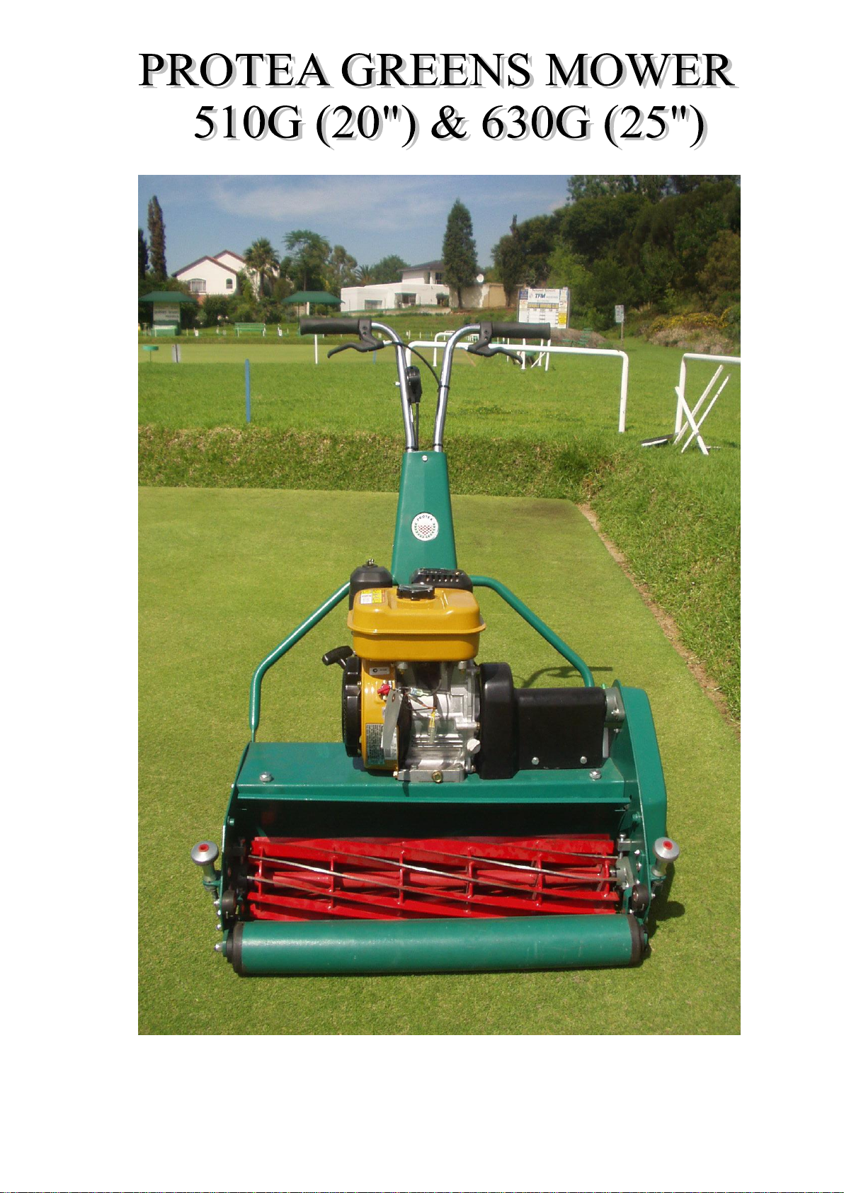
PROTEA 510G User manual
SPARES
&
INSTRUCTION
MANUAL
SPARES & INSTRUCTION
MANUAL

Ref. No.: CK 91/04496/23 Vat No.: 4830119907
Tel: 011 828 9935
011 822 1850
Fax: 011 828 6869
Mobile: 082 458 7257
Physical Address
BEDFORDVIEW
Telephone/Fax Numbers
Email: [email protected]
Email: sean@proturf.co.za
For further information on any Protea products, please visit our website www.proturf.co.za
Postal Address
Germiston
Gauteng
South Africa
Knights
2008 GAUTENG
Manufacturers of Protea Range of Mowers, Sodcutters, Scarifiers
PROTEA TURF EQUIPMENT cc
SOUTH AFRICA
32 Shaft Road
CONTACT DETAILS:
P.O.BOX 1673

1Know your controls. Read the owner's manual 13 Stop the engine whenever you leave the
carefully. Learn how to stop engine quickly in an mower, even for a moment.
emergency. 14 Stop the engine before pushing mower
2Make sure the lawn is clear of sticks, stones, across gravel drives, walks or roads.
bones, wire and debris. They could be thrown
by the blade. 15 Do not allow children or people
unfamiliar with these instructions to use
3Stop the engine and disconnect spark plug wire the mower.
before checking or working on the mower. 16 On slopes or wet grass, be extra careful of
4Before using, always visually inspect to see that your footing.
blade bolts and cutter assembly are not worn or
damaged. Replace worn or damaged blades 17 Never cut grass by pulling the mower towards
bolts in sets to preserve balance. you.
Damaged blades and worn bolts are a
major hazard. 18 Never use an electrically powered mower in
the rain or when grass is wet.
5Check all nuts, bolts and screws often, always
be sure the mower is in safe operating 19 Be extremely careful when using a ride on
condition. Use only replacement parts made
mower on slopes.
and guaranteed by the original manufacturer
of your mower 20 Never leave wind-up starters in a wound
condition.
6
Add fuel BEFORE starting engine. Avoid spilling
petrol and do not fill the tank while the engine is 21 Do not over speed the engine or alter governor
running or while you are smoking. settings. Excessive speed is dangerous
and shortens mower life.
7Do not mow whilst people, especially children
or pets are in the mowing area. 22 It is advisable to wear suitable eye protection
when operating a mower.
8Never use the mower unless the grass catcher ,
or guards provided by the manufacturer, 23 Turn the fuel off at the conclusion of mowing
are in position. and reduce the throttle setting during
engine run-ou.
9Do not mow barefoot or in open sandals.
Wear long trousers and heavy shoes. 24 Store fuel in a cool place in a container
specifically designed for the purpose. In
10 Disengage all blade and drive clutches before general, plastic containers are unsuitable.
starting.
25 Never pick up or carry a mower when it is
11 Start the engine carefully with feet well away operating.
from the blades.
12 Do not operate engine in a confined space where
exhaust fumes (carbon monoxide) can collect.
POWER LAWNMOWER SAFETY PRECAUTIONS
1
2
BEFORE USE
When the mower is removed from the carton the upper handle will be
in a folded position, therefore it will be necessary to pivot the handle
into the upright position. Secure the handle in this position with the
clamp screw & nut provided. When folding handle for storage, use
extreme care not to permanently bend clutch throttle controls.
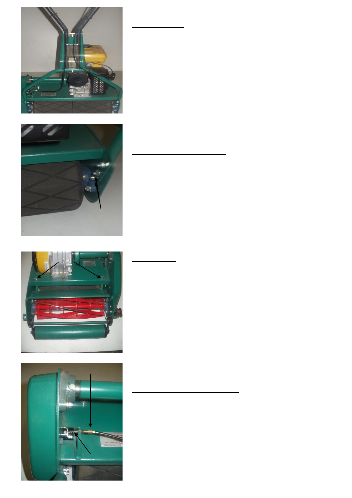
HANDLE ADJUSTMENT
Slacken 4 nuts (A) sufficiently to allow handle to be moved up and
down. Re-tighten with handle in selected position.
DEFLECTOR
Depending on cutting conditions e.g. wet grass, dry grass, high wind
velocity etc. it may be necessary to alter the angle of deflection into
the grass box. This is effected by loosening the thumb screws (A)
each side of the machine and moving the deflector plate in the desired
direction –move upwards to throw the grass higher and longer, or
downwards to throw the grass lower and shorter. Re-tighten screws
after adjustment.
CLUTCH CABLE ADJUSTMENT
The clutch operating pressure can be increased by releasing the lock
nut (A) and screwing the threaded adjuster (B) outwards a few turns
and re-tightening lock nut. This is necessary only if the unlikely
condition of clutch slip with loss of propulsion should occur.
A
A
B
A

3
CUTTER SETTING
The cutter is set correctly when it is lightly touching the bottom blade
along its FULL length. Hard bearing of uneven setting causes
excessive or uneven wear on cutting edges and also places undue load
on the engine. Before adjusting, lay the machine back with the handles
on the ground; making sure the petrol tap is “off”. To adjust cutting
cylinder, release clamp nuts (C), both sides of mower. Cutter is set
closer to the bottom blade by turning down (clockwise) the adjusting
screws on each side of the cutter (D) until cutter blades just contact
blade. If the cutter bears too hard on the bottom blade turn the
adjusting screws back at least a full turn and again carefully screw
down until correctly adjusted. Retighten clamping nuts.
HEIGHT OF CUT
The cutting height is raised by turning the adjusting knob (B) in a
clockwise direction. To cut lower, reverse procedure. When
adjusting for low cutting, do not set mower so low that the weight of
the machine is taken on the bottom blade instead of the front roller.
This would affect cutting, and also excessive load on the engine.
WARNING: Before making adjustments to the cutter or chains,
remove spark plug lead to avoid accidentally starting the engine.
CUTTER CHAIN ADJUSTMENT
Slacken nut (E). Move nylon chain adjuster
to give correct chain tension and retighten
nut. When correctly adjusted chain should
be slightly slack and not tightly stretched.
IMPORTANT: Check the chain tensioner
every time the cutting cylinder gets adjusted.
CLUTCH AND DRUM CHAINS
Both chains are adjusted by loosening two
nuts (G), and moving this sprocket upwards
which tightens both chains simultaneously.
After re-tightening nuts, some slackness
should be felt in each chain.
D
C
B
E
G
3

4
4
FIGURE 1
5
12
13
11
15
14
3
2
10
15
6
16
7
8
1
4

FIG DESCRIPTION PART NO
1 MOWER FRAME "G" LH 459306
2 GRASSBOX SUPPORT RUBBER with M8 x 30 cup sq nut (as from 01/08/2007 453085
3 CHAIN COVER 455777
4 CHAIN CASE MOUNTING SCREWS + M6 x 10 BOLTS/NUTS 1191908
5 630 GRASSBOX ASSY 458065
5 510 GRASSBOX ASSY 451290
6 510 ENGINE TABLE 451338
6 630 ENGINE TABLE 458056
7 MOWER FRAME "G" RH 459305
8 GRASSBOX ANTIVIBRATION MOUNTS 458085
9 SLOT COVER : NOT SHOWN Bottom 458080
10 630 TEASING RAKE BRUSH 458142
10 510 TEASING RAKE BRUSH 458141
11 630 TEASING RAKE BRACKET ASSY 458108
11 510 TEASING RAKE BRACKET ASSY 458109
12 CLUTCH COVER 3500500
13 CLUTCH COVER SEAL 458150
14 T. RAKE BRUSH M6 x 25 C.S.K SCREWS/NUTS STANDARD
15 T.RAKE BRACKET M6 x 20 CUP SQUARES/NUTS 458302
16 FRAME M8 x 20 SCREWS/NUTS STANDARD
17
CHAIN COVER STUD (NOT SHOWN) 458170
18 GRASSBOX HANDLE : OPTIONAL - NOT SHOWN 459270
19 SHIM WASHER FOR M6 SQUARE NUT (NOT SHOWN) 459474
5
SECTION 1 (REFER FIG.1)

FIG 2
6
1
2
5
3
3
4
6
7
8
9
8
9
10
9
8
12
9
8
11
9
8
13
9
8
14
9
8
15
9
8
16
9
8
16
9
8
15
9
8
14
9
8
17
9
8
18
9
8
19
9
8
20
9
8
20
9
8
21
9
8
22
9
8
22
21
9
8
23
21
9
8
23
21
9
8
24
21
9
8
25
21
9
8
26
21
9
8
26
21
9
8
27
21
9
8
27
21
9
8
28
21
9
8
28
21
9
8
29
21
9
8
31
21
9
8
30
21
9
8
31
21
9
8
30
21
9
8
32
21
9
8
32
21
9
8
33
21
9
8
34
21
9
8
35
21
9
8
35
21
9
8
36
21
9
8
37
21
9
8
38
21
9
8

FIG 2
FIG DESCRIPTION
PART NO
1510 LOW CUT BOTTOM BLADE (7 HOLES) 392041
1630 LOW CUT BOTTOM BLADE (9 HOLES) 458092
2BOTTOM BLADE SCREWS 2071924
3SOLE PLATE SCREWS M8 x 25 WITH NUT + SPRING WASH STANDARD
4510 SOLE PLATE WITH DEFLECTOR 459459
4630 SOLE PLATE WITH DEFLECTOR 459461
5510 FRONT ROLLER SHAFT 451048
5630 FRONT ROLLER SHAFT 458098
6⅜" UNF NYLOC NUT STANDARD
7R.H FRONT ROLLER BRACKET (NO SLOT) 457303
8L.H FRONT ROLLER BRACKET (WITH SLOT) 457307
9M8 NYLOC NUT AND WASHER STANDARD
10 510 WIRE SCRAPER 659538
10 630 WIRE SCRAPER 459125
11 M6 FLAT WASHER STANDARD
12 M6 NYLOC NUT AND FLAT WASHER STANDARD
13 CUTTER CHAIN ⅜" x 80 ROLLERS FOR 12T (DIAMOND) 2984590
14 FRONT ROLLER ADJUSTER AND KNOB 454694
15 DUST COVER CUP 2721960
16 FRONT ROLLER ADJUSTER ROD 454678
17 FRONT ROLLER ADJUSTER KNOB "E" CLIP 454723
18 ADJUSTER KNOB SHIM WASHER (1mm THICK) 459210
19 ADJUSTER KNOB SPRING 454707
20 ADJUSTER ROB ⅜" UNF NUT STANDARD
21 FRONT ROLLER BEARING 6202 4222222
22 FRONT ROLLER SEALS (35ᶲx 20ᶲx 7) 2724501
23 FRONT ROLLER SPACER 459562
24 510 FRONT ROLLER TUBE 451040
24 630 FRONT ROLLER TUBE 458097
25 CUTTING CYLINDER ADJUSTER BLOCCK 45948.1
26 CUTTING CYLINDER ADJUSTER ROD 45948.1
27 CUTTER ADJUSTER CAP SCREW 459480.3
28 FRONT ROLLER END CAP 451042
29 M8 x 12 BUTTON HEAD SCREW STANDARD
30 CUTTER BEARING HOUSING CLAPING BOLT 457301
31 CUTTER BEARING HOUSING PIVOT BOLT 457301
32 CAP SCREW LOCK NUT S/S 459480.6
33 12T ENGINE SPROCKET 453990
34 CUTTER SPROCKET 451485
35 CUTTING CYLINDER BEARING 1129100
36 WOODRUF KEY ⁵₃₂"3802051
37 CUTTING CYLINDER M12 NUT AND WASHER STANDARD
38 510 CUTTING CYLINDER x 12 BLADE 456252
38 510 CUTTING CYLINDER x 9 BLADE 456253
38 630 CUTTING CYLINDER x 12 BLADE 458077
38 630 CUTTING CYLINDER x 9 BLADE 458076
7

FIG 3
8
1
15
5
5
8
3
2
9
10
13
16
13
10
9
2
8
3
5
4
6
14
7
18
20
11
12
19
17

FIG DESCRIPTION PART NO
1630 REAR ROLLER BUSHED : RUBBERISED 458055
1630 DRUMS: SMOOTH 459155
1510 DRUM BUSHED : RUBBERISED 458006
1510 DRUM BUSHED : SMOOTH 459150
2DRUM BUSHES HD3115997
3BEARING HOUSING 1129110
4RATCHET : For Back Drum 175dia (Smooth Steel Drum Only) 459198
4
RATCHET : For Back Drum 165dia (Rubberised Drum Only) 458002
5DRUM BEARING HOUSING PIVOT BOLT/NUT/SPRING WASHES 457301
6PURCHASE BLOCK + 3/8 UNF NYLOC NUT BG/301727
7DRUM ADJUSTER BOLT + M8 NUT/SPRING WASHER 457304
8DRUM COLLAR + M8 x 20 GRUB SCREW + M8 LOCK NUT ROT/201404
9DRUM PAWL 458001
10 PAWL WASHER STAINLESS STEEL 3651247
11 DRUM SPROCKET 451207
12 DRUM CHAIN 2981385
13 PAWL CIRCLIP 1502474
14 DRUM SHAFT NUT 2441244
15 630 DRUM SHAFT 458090
15 510 DRUM SHAFT 458003
15 430 DRUM SHAFT 458004
16 WOODRUF KEY 3802051
17 REAR ROLLER SCRAPER BOLT M6 x 15 + NUT
STANDARD
18 SPACER : REAR ROLLER BEARING 458015
19 630 REAR ROLLER SCRAPER 458070
19 510 REAR ROLLER SCRAPER 458071
20 M 12 NUT + WASHER
STANDARD
21 DRUM ADJUSTER SHIM WASHER (NOT SHOWN) 459457
9
FIG 3
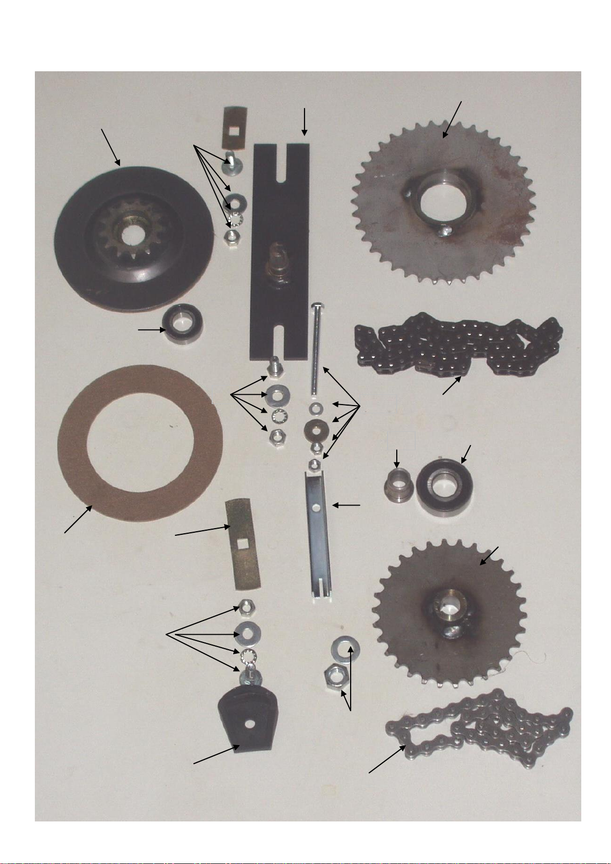
FIG 4
1
2
1
3
2
15
14
9
12
11
17
18
16
4
5
6
10
19
7
13
10

FIG DESCRIPTION PART NO.
1 SMALL INTER. SPROCKET ASSY. 451231
2 SMALL INTER SPROCKET BEARING (6003) 1126037
3 LARGE INTER. SPROCKET ASSY. 41T 459245
4 LARGE INTER. SPROCKET BEARING (6204) 1122422
5 INTER. ADJUSTMENT BRACKET ASSY. 451215
6 CUP SQUARE BOLT/NUT/WASHER M8 x 20 191011
7 M8 x 20 BOLT/WASHER/NUT/SPRING WASHER STANDARD
9 SLOT COVER: BOTTOM 458200
10 CHAIN ADJUSTER - SELF ADJUSTING 455770
11 CUP SQUARE BOLT/NUT/WASHER M8 x 30 191020
12 OPERATING LEVER RELEASE 453560
13 CLUTCH OPERATING BOLT/NUT/WASHER/LOCKNUT M6 x 50 1215863
14 LINING 333032
15
CHAIN 1/2 x 3/16 x.305 ROLLER CUTTER/CLUTCH (41T) 61 Rollers - 083 2981590
16
CHAIN 1/2 x 3/16 x.305 ROLLER CLUTCH/DRUM 38 Rollers - 083 2981385
17 DRUM SPROCKET 451207
18 NUT/WASHER M12 (Drum Sprocket) 2441244
19 SLEEVE CLUTCH WITH SHEAR PIN 454790
21 CHAIN ADJUSTER PIN - Not Shown 459130
22 CHAIN ADJUSTER SPRING - Not Shown 459131
11
FIG 4

12
FIG 5 HANDLE
11
9
10
21
20
13
5
4
3
1
7
3
6
8
22
17
17
18
18
2
12
12
14
14
15
15
19
16

FIG DESCRIPTION PART NO.
1 UPPER HANDLE ASSY 456375
2 510 LOWER HANDLE ASSY. 458026
2 630 LOWER HANDLE ASSY. 458095
3 HANDLE GRIP 1851071
4 CLUTCH WIRE ASSY. 451242
5
RH DEAD MAN LEVER OPTIONAL 403013
6 LH CLUTCH LEVER 403012
7 THROTTLE WIRE ASSY. 656720
8 CUP SQUARE M8 x 45 NUTS/SPRING WASHER UNIVERSAL
8 HANDLE GROMMET - NOT SHOWN 2721950
9 COVER PLATE ASSY. 453739
10 BOLT M6 x 15 NUT/SPRING WASHER UNIVERSAL
11 BOLT M8 x 40 NUT/ SPRING WASHER UNIVERSAL
12 CUP SQUARE M8 x 30 NUT/SPRING WASHER UNIVERSAL
13 HANDLE PIVOT 1216946
14 FLAT WASHER M8 x 30 x 2 UNIVERSAL
15
ANTIVIBRATION MOUNT ASSY OPTIONAL 458050
16 BOLT M8 x 30 NUT/SPRING WASHER UNIVERSAL
17 DEFLECTOR MOUNT CLAMP 451143
18 DEFLECTOR CLAMP SCREW 432428
19 510 DEFLECTOR ASSY 451135
19 630 DEFLECTOR ASSY 458068
20
MAGURA LEVER FOR CUTTER SPROCKET CABLE OPTIONAL 459100
21
CUTTER SPROCKET CABLE OPTIONAL 459035
22 CUTTER CABLE GROMMET, NOT SHOWN 2724510
13
FIG. 5 HANDLE

FIG 7
14
1
2
3
5
4
8
7
9
6
10
13
12
14
15
16
14
11

FIG DESCRIPTION PART NO
1 ENGINE 5HP 6200302
2 CENTRIFUGAL CLUTCH SHAFT FOR 430/510/630 FOR 12T 458037
3 CENTRIFUGAL CLUTCH BODY WITH SPRING 6200450
4 CENTRIFUGAL CLUTCH SHAFT OIL LITE BUSH H.D 3115997
5 CENTRIFUGAL CLUTCH TENSION SPRING 458040
6 ENGINE PACKING ROBIN EY20 458102
7
CUTTER CHAIN 3/8" for 9T Sprocket - 79Rollers 06B 2984810
7 CUTTER CHAIN 3/8" for 12T Sprocket 2981385
8 PILLOW BLOCK 1121200
9 CLUTCH SPROCKET 12T 459212
10 HEX BOLT M8 x 45
11 NUT 1/2" UNF for 12T SPROCKET STANDARD
12 M12 WASHER STANDARD
13 WOODRUF KEY NO 6 3802051
14 M6 x 25 COUNTER SUNK SCREWS STANDARD
15 PILLOW BLOCK SPACING 458048
16 M6 x 22 x 2 FLAT WASHER STANDARD
15
CENTRIFUGAL CLUTCH
FIG 7
This manual suits for next models
1
Table of contents
Other PROTEA Lawn Mower manuals


