Protech Audio 66708 User manual

PROTECH
The Protech Audio Model 66708 Dual Power
Supply is designed to provide regulated DC
power to the INTEGRA III SYSTEM audio
modules. The two separate 15-18 volt outputs are
designed to allow strapping together to create a
bipolar 15-18 volt configuration.
The Model 66708 is designed to be mounted in a
standard 19 inch wide EIA rack. The unit re-
quires only 3.5 inches of vertical rack space.
The line cord plugs into a standard three prong
117VACoutlet.Thefrontpanelhasfiveseparate
indicators. The power on/off switch incorpo-
rates a neon lamp, to indicate the presence of
powerto the AC circuit. Each includes two LED
indicators. A green LED shows the output is
providing the required DC voltage. A red LED
indicates a fault condition.
Three separate protection circuits are designed
into the Model 66708. The AC circuit is pro-
tected by a 3 amp slow-blow fuse.
EachDC output incorporates foldback/short cir-
cuitprotection. If the load attached to the output
is too great, the output volatage will be reduced.
If a short is applied to the output, the DC voltage
will reduce to zero volts, until the short is re-
moved. The unit will then automatically in-
crease the output voltage to the previously ad-
justed level.
The Model 66708 also features local or remote
sensingoftheregulatedoutputvoltage. Theunit
is shipped from the factory strapped for local
output voltage. The unit is shopped from the
factory strapped for local sensing. The output
voltage at the rear terminal strip, will remain
constant, from no load to full load. The terminal
strip jumpers may be removed, and the sensing
terminals wired to a remote location. This ar-
rangement will insure that the output voltage
will remain constant at the load. If the load is in
the same rack as the power supply, it is not
usually necessary to provide a remote sensing
configuration.
®66708
DUAL POWER SUPPLY
INSTALLATION & OPERATION MANUAL
Protech Audio Corporation, 192 Cedar River Road, Indian Lake New York, 12842 Voice 518-648-6410 Fax 518-648-6395
www.protechaudio.com
11/07
INSTALLATION
Page 2
The Model 66708 is designed to mount in a standard 19" EIA
rack. The unit should be mounted in the bottom of the rack. A
minimum of a one rack space ventilation panel should be
mounted directly above the power supply, to provide adequate
ventilation.
Checkthat the AC line voltage and amperage rating are correct
beforeconnectingthelinecord. Therating should be120VAC,
with at least 3 amperes of current available.
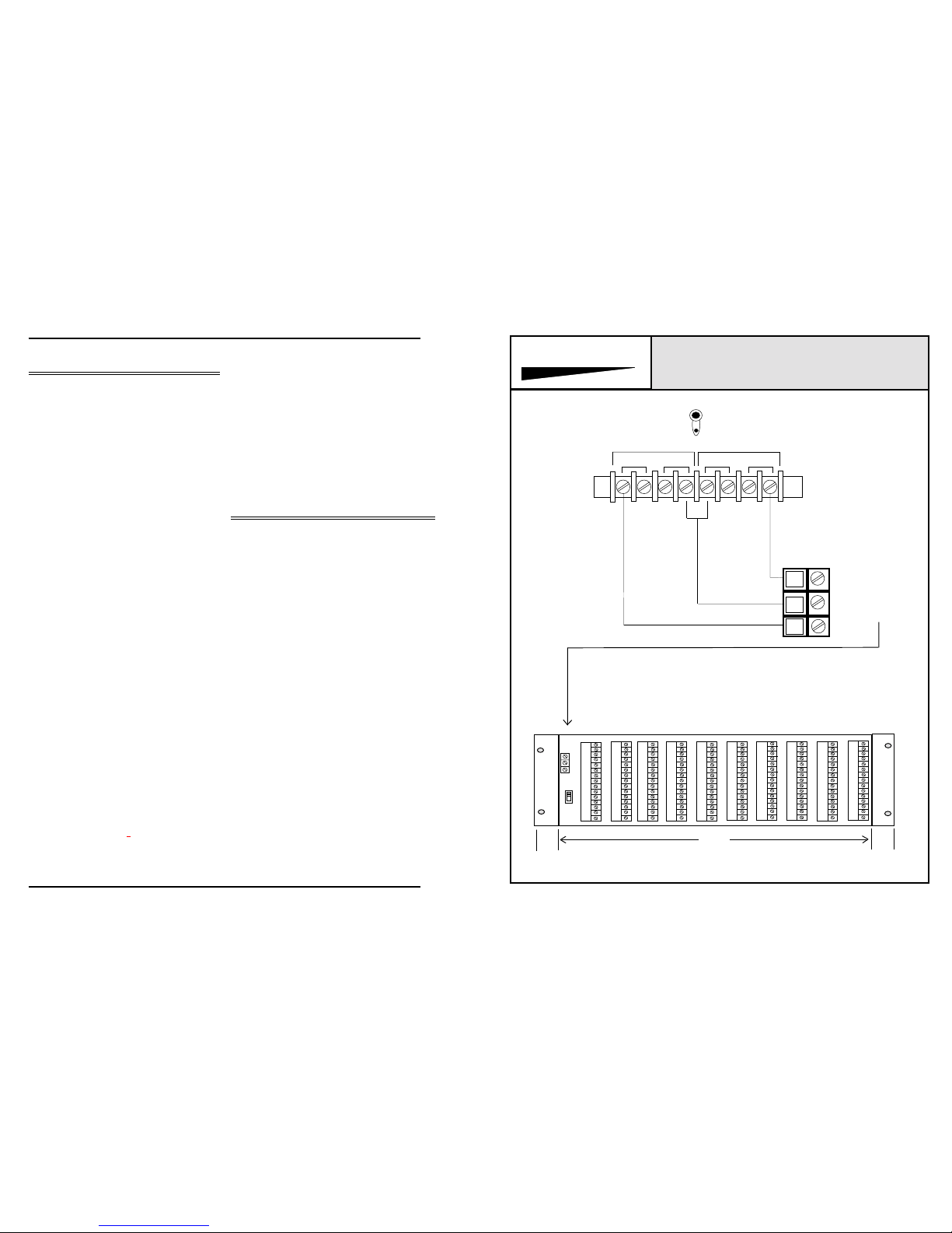
The DC connections should be made using a minimum of
18AWGwire. In the local sensing mode, three conductorswill
be necessary. In the remote sensing mode, seven conductors
will be required. The connections are made as indicated in
Figure 1. After making all connections from the power
supply to the load, turn on the unit, and using a voltmeter,
verify that the voltages and the polarity are correct at the load.
The output voltages are adjustable via potentiometers, which
are accessible at the rear of the power supply chassis.
The actual steps for installation for the Model 66708 Dual
Power Supply are as follows:
1- Mount the Model66708intothe lowest available positionin
the rack.
2-Mountasinglerackspace(minimum)ventilationpanelinthe
rack, immediately above the power supply.
3 - Check the AC receptacle for proper voltage and current
rating before connecting the line cord.
4 - Plug in the line cord, and turn unit on. The neon power
indicatorintheon/off switch should illuminate. The two green
LED DC voltage indicators should illuminate.
5 - Turn unit off, and wire the outputs to the load, observing
connection points as indicated in figure 1.
6-Turn unit on, and using aDC voltmeter, measure the DC
voltage at the load. In the bipolar configuration*, the voltage
between GROUND and +VDC should measure 18 volts DC
positive. The voltage between the GND and -V should
measure 18 volts DC negative. The voltages may be adjusted
by using the potentiometers thatare mounted on the rear of
the power supply chassis.
*(ALL INTEGRA III SYSTEM
Amplifiers require +15-18VDC)
7 - Check the polarity of the voltage at the load. Between Pins
GND and+V, itshouldmeasure+18 volts. BetweenpinsGND
and -V, the voltage should measure -18 volts.
Yourinstallation isnowcomplete. Continuous operationofthe
Model66708isnormal,andrequiresnofurtheroperationsfrom
support technicians. There are no adjustments which must be
made on a periodic basis. However, periodic testing of the
overall system may be specified by the system designer.
CIRCUIT DESCRIPTION
The Model 66708 is a state of the art dual power supply. The
unit has two independent regulated outputs. Each outputmay
be used separately, or strapped together to form a bipolar
configuration. The bipolar arrangement is the type usually
used for the INTEGRA III SYSTEM.
Thepower transformeristoroidial inconstruction. Thistypeof
powertransformeremanatesamuchsmallerACfield,whichis
of great importance when working with low level audio ampli-
fiers. The secondary of the toroid has two separate windings,
one for each power supply output.
Therearetwoseparaterectifier/regulatorcircuitsineachModel
66708. The rectifier is a standard full wave bridge rectifier
followed by two 4700uf filter capacitors. The voltage regula-
tion, and current sensing are derived by using an I.
C. regulator, the MC1723. The output current capability is
increased by the addition of 4 external pass transistors
(TIP120)
for each output.
NOTE: Power supply outputs are floating with re-
spect to chassis and earth ground.
PROTECH
OUTPUT #2 OUTPUT #1
MODEL 66708
®
1.5" 16.5"
*
REAR VIEW BACKPLANE/CARD FRAME ASSEMBLY
*** *****
*
GND ON
GND
LIFT
10 9 8 7 654321
*Space used for additional connectors or trimpots as needed for application 1.5"
GND
V+
V-
+18V
-18V
GND
DETAILED
VIEW OF
POWER
CONNECTOR
BELOW
CONNECTION DIAGRAM FOR MODEL 66708
TO BE USED WITH 857B CARD FRAME.
Leave Factory Installed
Sensing Jumpers In Place,
Unless Remote Sensing Is
Required
NOTE:
EXTERNAL CONNECTIONS
SENSING V+
V- V- SENSING V+
Model 857B
Power Supply Output is floating with respect to ground. It may be
necessary, depending on the individual installation, to provide a
ground strap from the card frame “GND” pin to power supply
ground.
Ground


