Protect CRW 200 User manual

edition: PROTEKT_EN-01
CRW 200
RETRACTABLE TYPE FALL ARRESTER
RESCUE LIFTING DEVICE
SERVICE MANUAL
CONTENTS
1. CRW 200 Technical pecification.......................................
1.1. Description ...............................................................
1.2. Technical data ..........................................................
1.3. Standards .................................................................
1.4. Identification and marking ........................................
2. Term of ervicing ..............................................................
3. Servicing equipment ..........................................................
4. Servicing operation ..........................................................
4.1. The de ice dismantling ..................................................
4.2. The retracting spring set maintenance and inspection ..
4.3. The drum set maintenance and inspection ....................
4.4 The brake set maintenance and inspection ....................
4.5. The winch unit dismantling and maintenance ................
4.6. The de ice rebuilding ....................................................
5. Po t a embly check .........................................................
6. CRW200 - Spare part ........................................................
2
2
2
2
2
3
3
4
4
6
6
7
9
10
12
13
CRW 200 Ser ice Manual 2/13
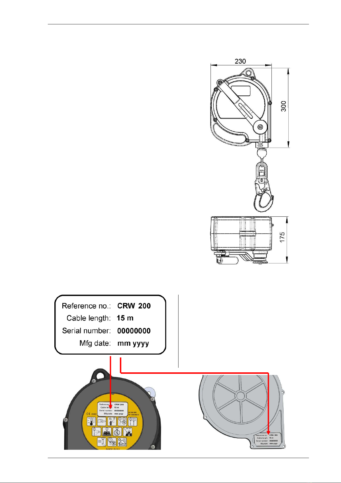
1. CRW 200 TECHNICAL SPECIFICATION
1.1 De cription
The CRW200 is a retractable type fall arrester
including rescue lifting de ice.
The retractable type fall arre ter mode. When
a pulling force is applied to the cable wound on
the spool, it unwinds with resistance of the
retracting spring. When pulling force is remo ed,
the cable retracts and is wound back onto the
spool inside the de ice. When the user falls and
the cable starts to unwind rapidly, the de ice is
locking, pre ent unwinding of the cable and
absorb the kinetic energy of the fall.
The re cue lifting device mode. The de ice is
equipped with hand operated winch with
automatic brake which pre ent against self-
contained descent of a person. In the
consequence of cranking, the de ice cable is
mo ed up and down under control.
1.2 Technical data
Max. rated load: 140kg
Min. rated load: 50kg
Working length: 15m
Dimensions: acc. to drawing (in [mm])
Weight: 11kg
Cable diam. 4,8mm
1.3 Standard
EN 360:2002
EN1496:2006 – class B
1.4. Identification and marking
The CRW 200 de ice is marked with four
descripti e elements, with the aid of
identification label placed on the de ice outer
shell and repeated inside.
The identification elements:
• Reference number
• Serial number (a unique 7-digit number).
• Date of manufacture.
• Cable length.

CRW 200 Ser ice Manual 3/13
2. TERMS OF SERVICING
Standard EN 365 regulates the obligation to
ser ice and maintain personal protecti e
equipment (PPE). Such ser icing and
maintenance should also be the responsibility of
e ery user.
After each arre ted fall or exce ive load and
at lea t every 12 month , the retractable type
fall arre ter (re cue lifting device) mu t be
returned for in pection and maintenance
performed by the manufacturer or an
authori ed ervice. The fall arre ter mu t
al o be erviced if any deficiency or
problem occur when u ing the device.
Ser icing and maintenance can be performed by
authorised personnel only. The manufacturer is
not liable for ser icing errors or omissions or
improper ser icing.
In the e ent of any problems or questions, the
manufacturer pro ides all required information
or performs the necessary testing and ser icing
of the de ice.
This ser ice manual is intended as basic
maintenance and ser icing guide only and does
NOT substitute proper training offered by
PROTEKT.
Ser icing and maintenance must meet the
requirements of the EN 360; EN1496 and
EN365 standards and be performed with proper
care and attention.
For correct ordering, ser icing and maintenance
personnel should be familiar with the
specification of replacement parts.
All ser icing and maintenance should be
recorded in the de ice’s IDENTITY CARD.
3. SERVICING EQUIPMENT
Common tools and some special equipment
a ailable from authorised ser ice centres and
the manufacturer are required for ser icing and
maintenance of CR 200. Manufacturer
recommends lubricants shown in the images
below or lubricants with similar specification
should be used in the product.
Materials for maintenance
Anticorrosion grease for
lubricating the retracting
spring.
For example: Abel Action
7; D40 or a lubricant with
similar properties.
Anaerobic adhesi e for
thread locking bolts.
- iscosity 5 ± 2Ps
- thread gap 0.1 ÷ 0.3 mm
For example: LOXEAL 55-
03; LOCTITE 262
Thick uni ersal grease –
for example ŁT 40
Basic tools (recommended)
CRS 04 – Rotating Jig.
CRS 04-04 Extension Kit
for CRW200
Torque spanner with 32
mm hexagonal attachment
A pliers for retaining rings
of the diameters: Ø 8mm;
Ø 20mm and Ø 38mm.
Allen wrenchs, size: 3, 4, 5
& 6 mm.
Torx type wrenches: T20 &
T-25
Cross tip screwdri er –
PZ 2/PH 2 (ISO 8764)
Support tools and equipment
Cur ed tip uni ersal pliers.
Flat tip screwdri er.
Diagonal cutter.
Flat brush for cleaning and
application of liquid
lubricants onto mo ing
components.
Hand and eye (or face)
protection equipment.

CRW 200 Ser ice Manual 4/13
4. SERVICING OPERATIONS
Prior to maintenance, please ensure that all
necessary tools, replacement parts and lubricants
are a ailable at hand. When ser icing the
retractable type fall arrester, special attention
should be paid to any problems such as jamming
of the mechanism, corrosion or locked cable. The
source of the problem must be identified.
Carefully check whether all markings are legible.
Inspect the casing unit to see if there are any
cracks, dents or chipped-off pieces. If any
problems are detected, the affected parts should
be replaced.
4.1. The device di mantling
4.1.1
• Unscrew 6 screws (1)
with the aid of Torx type
wrench T-25.
• Open a cover (2) from
cable drum side.
4.1.2
• Take off a clip size 38mm
(3) from cable pilot sleeve
(4).
4.1.3
• Pull out the cable sleeve
(4) from casing opening
(5) and move the cable
out of the opening (5).
• Turn a cable set (6) to the
left direction to release a
retracting spring tension.
4.1.4
• Unscrew M6 bolt (7) and
washer (8).
• Take off the cable drum
set (6) from a shaft
• Take off the parallel key
(9) from the shaft.
1
2
1
3
F
6
8
7
9
6
4
4
5

CRW 200 Ser ice Manual 5/13
4.1.5
• Unscrew the bolt (10)
with the aid of cross tip
screwdri er. Take off the
washer (11) and crank
plate (12).
• Unscrew the (13) bolt
with the aid of Allen
wrench and (14) bolt with
the Allen wrench 3mm.
• Take off the crank (15)
from the shaft.
4.1.6
• Unscrew the (16) nut and
take off the crank shaft.
• Unscrew the (19) screw
with the aid of Allen
wrench 5mm and take off
the (18) spring and (17)
pin.
4.1.7
• Unscrew 6 screws (18)
with the aid of Torx type
wrench T-25.
• Open the cover set (19).
• Unscrew licking unit (20)
and take off the washer
(21)
4.1.8
• Unscrew 3 M8 bolts (22)
with the aid of Allen
wrench 6mm and take off
the winch set (23) from
the casing.
• Take off the locking pin
set (20) from the casing.
4.1.9
• Take off snap ring 20mm
(24) and take off the
brake unit (25) from the
shaft.
• Take off the snap ring
20mm (26) and washer
(27) from the shaft (28).
• Take off the shaft (28)
from the casing
4.1.10
• Clean and inspect: main casing, bush and dog's gear, washer.
• Replace snap ring (26) with new one.
10
11
12
13
14
16
17
18
19
15
18
19
21
20
23
22
20
24
25
27
26
28

CRW 200 Ser ice Manual 6/13
4.2. The retracting pring et maintenance and in pection
4.2.1
• Clean and inspect the
constituent parts. Pay
special attention on the
retracting spring internal
ending (1) shape.
• Lubricate the retracting
spring, using openings
(1) and (2) from cable
drum side.
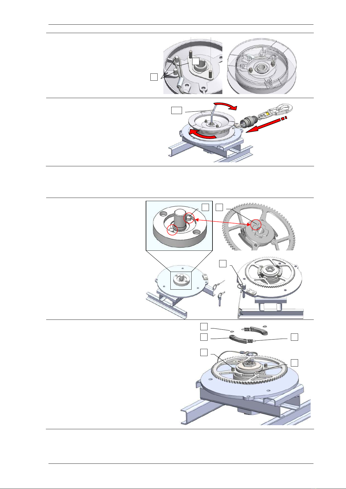
4.3. The drum et maintenance and in pection
4.3.1
• Prepare the Rotating Jig. Seat the CRS
04-04 Extension Kit (1) in the CRS 04
base (2).
4.3.2
• Install the cable drum set on the
rotating jig.
• Test the connector for correct
operation. If the connector is equipped
with fall indicator, check if it is not
deformed.
• Unwinding the cable from the drum,
inspect it against: broken wires,
unbraided strands, permanent
deformations, excessive corrosion.
• Check the rope ferrules (3) against
cracks or deformation.
• Check if the rope's end (4) project
outside the ferrule.
• Replace the entire cable set in case of
any damages or abnormality.
4.3.3
• Take off the cable drum from the
Rotating Jig.
• Unscrew the screwing connection
(5), (6), (7) and dismantle all
parts of the set.
• Check all the parts against:
cracks, deformation and
corrosion. Replace wrong parts if
necessary.
2
1
3
4
5
6
7
2
1
lubricate
CRW 200 Ser ice Manual 7/13
4.3.4
• Rebuild the winch set in reverse
order. Pay attention on the
proper installation of the cable
loop (8) on the pins (9).
4.3.5
• Install the drum on the Rotating
Jig.
• ind the cable by turning the
drum to the right with the aid of
Allen wrench 6mm (10).
4.4. The brake et maintenance and in pection
4.4.1
• Seat the brake unit on the
Rotating Jig. Pay attention to
lock the Jig's pin (1) in the
part's relief (2).
• Secure the rotating jig table
against rotation with the aid
of pin (3).
4.4.2
• Take off the Φ8 locking ring (4) and the dog
(5) from the dog’s axle (6).
• Detach the dog's spring (7) from the pin (8).
Carefully inspect:
− dogs (5) - attack edge cannot be worn down;
− dog's axle (6) - any axle movement is a
failure.
− the dog’s springs (7) - the spring’s threads
should adhere each other and the spring eye
should be round;
Carefully clean all parts. Replace, if
appropriate.
8
9
9
10
1
2
3
4
6
5
7
8

CRW 200 Ser ice Manual 8/13
4.4.3
Unscrew the M28 nut (9).
4.4.4
Dismantle all the parts:
• M28 Nut (9);
• Spring washer (10);
• Pressure plate (11);
• Friction ring – 1
st
(12);
• Gear (13);
• Friction ring – 2
nd
(14);
• Support plate (15);
• Bush (16).
Check carefully all the parts against
any damages and/ or corrosion.
Metal parts may be cleaned with the
aid of extraction naphtha or similar
solvent. Replace, if appropriate.
Don t clean or repair the friction
ring. If the ring is worn down or
damaged, it should be replaced with
new one.
Assembly the components of the set in
reverse order. (The M28 nut thread
must be greased before screwing)
4.4.5
• Set up a torque spanner with
the torque value of 60 Nm.
• Tight the M28 nut (9) with the
specified torque.
4.4.6
• Attach the dog's springs (17)
to the pins (18).
• Mount the dogs (19) onto
dog's axles (20)
• Secure the dogs with the aid
of Φ8 locking ring (21). Use a
new locking ring.
6
0 Nm
grea e before
crewing
9
9
20
19
17
18
21
13
12
11
10
9
14
15
16

CRW 200 Ser ice Manual 9/13
4.5. The winch unit di mantling and maintenance
4.5.1
• Unscrew two M4 screws (1) with the aid of
Torx type wrench T20.
4.5.2
Dismantle winch unit in the following steps:
• Take off the parallel key (2).
• Take off the crank shaft (4) and the parts
(5), (6), (7) from the body (3).
• Take off friction rings (5), (7) and ratchet
wheel (6) from the shaft.
4.5.3
Inspect the parts against any damages or corrosion.
Metal parts may be cleaned with the aid of extraction naphtha or similar solvent.
Don t clean or repair the friction ring. If the ring is worn down or damaged, it should be
replaced with new one.
Rebuild the winch unit in the following steps:
4.5.4
• Put on one friction ring (5) onto shaft.
Grease the shaft in pointed place.
4.5.5
• Put on the ratchet wheel (6) and friction
ring (7) onto shaft.
4.5.6
• Grease in the pointed places.
4.5.7
• Put in the shaft set (8) into body.
• Mount the parallel key (9) in the body slot.
• Screw two M4 bolts (10).
grease
1
2
3
4
5
7
5
1
6
6
7
grease
grease
grease
grease
grease
8
10
9

CRW 200 Ser ice Manual 10/13
4.6. The device rebuilding.
4.6.1
• Grease the main shaft (1) in
the pointed place.
• Mount the shaft (1) into
casing.
• Mount the washer (2) and
Z20 snap ring (3).
4.6.2
• Mount the parallel key (4)
into shaft's slot.
• Mount the brake set (5) onto
shaft.
• Mount the Z20 snap ring (6)
onto shaft.
4.6.3
• Set the locking pin set (7)
into casing hole.
• Set the winch set (8) into
casing, screw preliminary
the locking pin (7) set to
winch set (without
tightening) and screw 3 M6
screws (9).
• Tight the locking pin set (7)
screwing connection to
winch set (8).
4.6.4
• Turning with the main shaft, position
the shaft's groove (9) opposite the
retracting spring ending (10) so that
inserting of the spring ending into
groove is possible.
• Put on the retracting spring cover set
(11) on the base. Pay attention to
insert the ending (10) of the retracting
spring into shaft's groove (9) and the
hole (12) on the winch set body (13).
• ith the aid of Torx type wrench T25
screw 6 x M5 bolts (14).
4.6.5
• Mount the parallel pin (15);
spring-G (16) and M10
screw (17) into cover's hole.
• Mount the crank nut (18)
onto crank shaft.
grease
1
2
3
4
5
6
7
9
8
7
grease
10
9
14
13
12
11
grease
15
16
17
18

CRW 200 Ser ice Manual 11/13
4.6.6
• Mount the crank (19) and
the screws (20) and (21).
Glue the screws with the aid
of anaerobic adhesive.
• By turning the crank to the
right, tight the winch brake.
(You should listen sound
like - "click ... click ... click).
• Mount the crank plate (22)
onto shaft. Pay attention to
position the crank plate in
relation to crank according
arrangement (23).
• Fix the crank plate with the
aid of washer (24) and M5
screw (25). Glue the screw
with the aid of anaerobic
adhesive.
4.6.7
• Mount the parallel key (26)
into shaft slot and put the
drum set (27) on the shaft.
• Fix the drum set with the aid
of M6 screw (28) and
washer (29).
4.6.8
• Rotate the drum unit 8 full
turns to the left in order to
make initial tension of the
retracting spring.
• Insert the cable and the
bumper’s spring set (30)
into casing slot.
• Mount the Z38 locking ring
(31) onto bush.
4.6.9
• Mount the drum's cover (32)
onto body.
• Fix the cover with the aid of
6 x M5 screws (33). Use the
Torx type wrench T25.
anaerobic
adhesi e
click ... click ... click
x
8
19
glue
21
20
23
22
24
25
glue
glue
25
21
20
26
27
28
29
30
31
33
32
CRW 200 Ser ice Manual 12/13
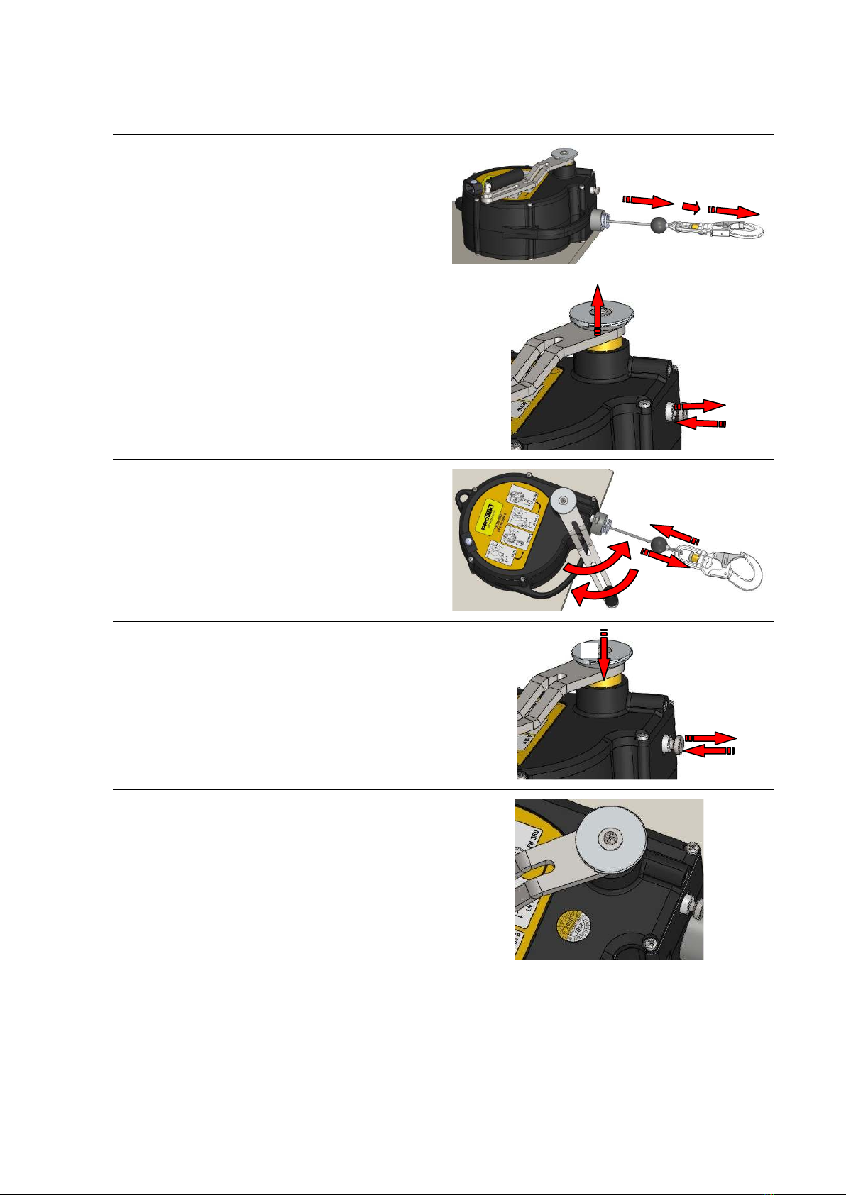
5. POST-ASSEMBLY CHECK
5.1
Under EN360 mode:
• unwind the cable fully from the device,
• during unwinding, pull the cable abruptly –
make sure that the dogs engage,
• release the cable - make sure that the
cable retracts.
5.2
Change over the device to EN1496 mode
• unlock the winch with the aid of the locking
pin,
• pull the crank plate,
• lock the winch by loosening the locking pin.
5.3
By turning the crank in both direction make
sure that the cable is moved.
6.4
Back to EN360 mode.
5.5.4
Apply the next inspection sticker and mark
relevant date in the next year.
* * * * * * * *
3
1
2
1
3
2

CRW 200 Ser ice Manual 13/13
6. CRW 200 - SPARE PARTS
Table of contents
Popular Lifting System manuals by other brands


PALAZZANI
PALAZZANI RAGNO XTJ 32 / C Operation and maintenance manual

Harmar Mobility
Harmar Mobility Pinnacle Installation and service manual

Herkules Hebetechnik GmbH
Herkules Hebetechnik GmbH K1200-HLS-64 Operating manual and test record

morse
morse 400A-96-114 Operator's manual

Sealey
Sealey MC500 instructions

WPG
WPG MRT411LDC operating instructions