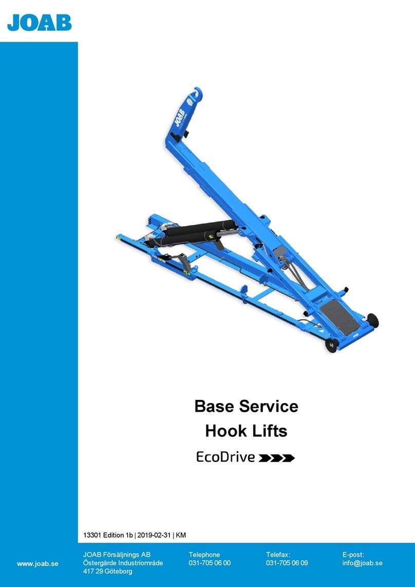
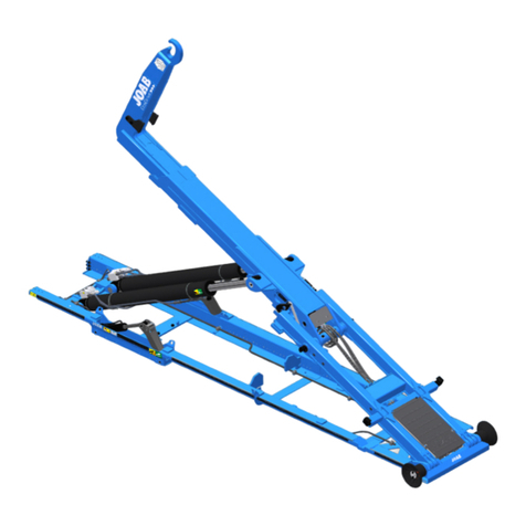
Joab L Series Original operating manual

Base Service
Hook Lifts
L and LA
www.joab.se
13298 Edition 5 | 2019-10-20 | KM
JOAB Försäljnings AB
Östergärde Industriområde
417 29 Göteborg
Telephone
031-705 06 00
Telefax:
031-705 06 09
E-post:
info@joab.se

ii Service Instruction: Hook-Lift L and LA | 13298 Edition 5 | 2019-10-20

iii
Service Instruction: Hook-Lift L and LA | 13298 Edition 5 | 2019-10-20
Table of Contents
Introduction v
Overview 1
Required Equipment 2
Safety 2
Group 1 – Replace Service Components 3
Group 2 – Torque the Chassis Brackets 5
Group 3 – Operation and Function Check 7
Group 4 – Inspection and Adjustment 11
Round Sensors 12
Square Sensors 13
Group 5 – Hydraulic Pressure Control 25
Group 6 – Lubrication 29
Appendix 1 - Control Stick Functions 31
Electrical Controlled Systems - CBW controller 31
Electrical Controlled Systems - Two Button Controller 33
Air Controlled Systems - Two Button Controller 34
Air Controlled Systems - Seven Button Controller 35
Appendix 2 - CBW User Interface 37
Icon Definitions 37
Safety Warnings 39
Contact Information 41
Service Packets and Warranty 41

iv Service Instruction: Hook-Lift L and LA | 13298 Edition 5 | 2019-10-20
Table of Contents

v
Introduction
This instruction describes how to perform a base service on Hook-Lifts, models L and LA.
This instruction is based on the original mounted equipment only. Refer to the relevant sup-
plier’s documentation for all other optional or auxiliary equipment.
JOAB takes no responsibility for consequences that occur due to work carried out by non-pro-
fessionals.
The specifications, constructions, and illustrations found in this service procedure are not bind-
ing. JOABAB retains the right to make changes without prior notice.
Before performing a service on a Hook-Lift make sure that you have read and are fully aware
of all safety warnings in the operator manual. Failure to do so can lead to serious injury or
damage to equipment.
Always bare in mind that it is the operator that is responsible for handling the Hook-Lift.
© JOABAB
Service Instruction: Hook-Lift L and LA | 13298 Edition 5 | 2019-10-20

vi Service Instruction: Hook-Lift L and LA | 13298 Edition 5 | 2019-10-20
Introduction

1
Overview
The following image provides an overview of the Hook-Lift and its components. These com-
ponents will be referred to throughout this procedure. Items marked with an asterisk (*) are
optional equipment.
A. Sub frame
B. Auxiliary-lifting-arm
C. Inner rear section
D. Intermediate section
E. Extending section
F. Hook
G. Hook post
H. Hydraulic-lock
I. Folding hook post (LA models only)*
J. Safety hook (LA models only)*
K. Centre lock
L. Spreader flap deployer (accessory)*
M. Rollers
Service Instruction: Hook-Lift L and LA | 13298 Edition 5 | 2019-10-20

2
Required Equipment
The following table lists the materials required to carry out the base service.
Material Required Quantity Part Number Viscosity
Filter kit (Base) 1 1008902 --
Hydraulic filter - included in filter kit (1) (1651)
Air filter - included in filter kit (1) (4650) --
O-ring (return filter) - included in filter kit (1) (1631-3) --
High pressure filter kit 1 1008902-1 --
High pressure filter (1) 49402 --
Filter- LS (1) 1523559 --
Hydraulic oil (can be customer specific) 70 – 230 litres -- SHS 32/46
Lubricating grease: NLGI0 or thicker -- -- --
Table 1: Required materials
Safety
There is a serious risk of injury when working with the hook-lift if due care is not taken. Make
sure that all personnel are competent and aware of the risks before working on the hook-lift.
Before starting work with the hook-lift, read and adhere to the safety warnings
provided under "Safety Warnings", on page 39. Failure to adhere to the safety
warnings can lead to serious injury or damage to equipment. In addition, read and
adhere to all safety warnings provided in the vehicle's documentation.
Care must be taken when working with hydraulic components. There is a risk of
hydraulic fluid leaking under high pressure that can lead to injury. Make sure that
all personnel are trained in the correct procedures before working with the hydraul-
ics.
Service Instruction: Hook-Lift L and LA | 13298 Edition 5 | 2019-10-20
Overview

3
Group 1 – Replace Service Components
1:1 Thoroughly clean the area around the cap for the air-filter (1) and the area around the
hydraulic-filter (2), on the hydraulic tank. Then replace the following items with new
ones:
1. The air filter.
2. The hydraulic filter.
3. The O-ring for the hydraulic filter
1:2 Replace the high pressure filters HF & LS as follows:
lFor hook-lifts equipped with a variable pump, replace both the HF and the LS fil-
ter. The LS filter is mounted as standard inline to the pump.
lFor hook-lifts L18X and L26, replace the HF filter.
Service Instruction: Hook-Lift L and LA | 13298 Edition 5 | 2019-10-20

4
1:3 Clean the area around the hydraulic-tank's drain plug (1). Unscrew the plug and com-
pletely drain the oil. Then replace the drain plug and refill the tank with new oil. Refer
to "Required Equipment", on page 2 for details of the correct oil to use.
Service Instruction: Hook-Lift L and LA | 13298 Edition 5 | 2019-10-20
Group 1 – Replace Service Components

5
Group 2 – Torque the Chassis Brackets
2:1 Inspect and make sure that all shims for the chassis's fastening brackets, where
applicable, are not loose and correctly positioned.
NOTE: Before the chassis brackets are first fastened, during assembly, the gap
between them is measured, as shown below. If the gap is greater than 2 mm, shims
are placed in between them before torquing of the bolts.
2:2 Check all of the chassis’s fastening brackets and make sure that all bolts are correctly
torqued. Use the toque settings listed below in Table 2 for all bolts, except head bolts.
For head bolts, use a torque value of 40 Nm.
Thread (Metric) Class 8.8 Class 10.9
M14 128 Nm 181 Nm
M16 197 Nm 277 Nm
Table 2: Torque setting for chassis brackets
Provide below are some examples of the chassis brackets. The actual brackets used
may be different to those shown, however the torque settings are the same.
Service Instruction: Hook-Lift L and LA | 13298 Edition 5 | 2019-10-20

6Service Instruction: Hook-Lift L and LA | 13298 Edition 5 | 2019-10-20
Group 2 – Torque the Chassis Brackets

7
Group 3 – Operation and Function Check
3:1 Inspect and make sure that all of the hook-lift's lighting functions correctly. Make sure
to also inspect the reverse lights when the vehicle is put in reverse gear.
3:2 Inspect and make sure that the hook-lift's work lights function correctly.
3:3 Turn the hydraulic pump ON and operate all of the hook-lift's main hydraulic functions,
under load. Verify that they function fully and correctly. Verify that the hydraulic func-
tions stop as expected at their end points, such as when shunting.
When operating the hook-lift's functions under load, listen to the vehicle's engine and
hydraulic pump and verify that all functions as expected. Look for hydraulic leaks and
listen for unusual noises.
NOTE: The type of control-stick installed in the vehicle is dependent upon the system
and option ordered. Refer to the following for information specific to each type of con-
troller and its operation.
1. "Electrical Controlled Systems - CBW controller", on page 31
2. "Electrical Controlled Systems - Two Button Controller", on page 33
3. "Air Controlled Systems - Two Button Controller", on page 34
4. "Air Controlled Systems - Seven Button Controller", on page 35.
3:4 Verify that all buttons on the hook-lift's control-stick function correctly.
3:5 Check that the emergency stop button functions correctly, as described below. It is nor-
mally located below the steering wheel, as shown.
Service Instruction: Hook-Lift L and LA | 13298 Edition 5 | 2019-10-20

8
Turn the pump for the hook-lift ON, operate the hook-lift, and then activate the emer-
gency stop to verify that it stops the hook-lift from working. Reset the emergency stop,
and then verify that the hook lift is able to function again.
3:6 Inspect and verify that all LEDs on JOAB's display panel function correctly, as shown
below.
If the vehicle is equipped with a CBW controller, verify that its corresponding icons
function in the display, as shown:
NOTE: Certain vehicle manufacturers have indicator lights for the hydraulic-pump in
the driver's display. Make sure that you are aware of any additional lights that the
vehicle is equipped with, that relate to the operation of the hook-lift, and that they also
function correctly.
1. Make sure that the LED for the pump (1) illuminates when the hydraulic pump
for the hook-lift is active.
2. Make sure that the LED for the hydraulic-lock (2) illuminates when the
hydraulic-lock is open.
3. Make sure that the LED for the centre-lock (3) illuminates when the centre-lock
is open.
3:7 For vehicles equipped with a CBW controller perform the following additional checks:
1. Verify that the buttons for functions F1 to F4, the arrow buttons, and the OK but-
ton all function correctly. Refer to "Appendix 2 - CBW User Interface", on page
37
2. Verify that the screen, all icons, and menus work correctly. Make sure to view
the "Page Set-ups", the "Diagnostics and Statistics" page, and the " Hook pos-
itioning" page.
3. Verify that the following warnings are displayed in the user interface when the
pump is turned off and the corresponding state is active.
Service Instruction: Hook-Lift L and LA | 13298 Edition 5 | 2019-10-20
Group 3 – Operation and Function Check

9
Service Instruction: Hook-Lift L and LA | 13298 Edition 5 | 2019-10-20
Group 3 – Operation and Function Check
Icon Meaning
The hook lift is not in drive status. It is not fully retracted.
The center-lock is open.
The hydraulic-lock is open.
The safety-hook is open (LA models only).
Table 3: User interface warnings
3:8 Verify that the LEDs for the trailer warning lights, as shown below, function correctly,
as listed:
NOTE: This is optional equipment. It is not standard.
1. Make sure that the red LED illuminates when the tow hitch is open.
2. Make sure that the green LED illuminates when the tow hitch is closed.
3:9 Operate the radio controller for the hook-lift (where applicable) and verify that it func-
tions correctly for all standard and optional equipment, as listed below.
NOTE: The radio controller is optional equipment. It is not standard.
1. Verify that the emergency stop button on the radio controller functions correctly.
Turn the pump for the hook-lift ON, operate the hook-lift, and then activate the
emergency stop to verify that it stops the hook-lift from working. Reset the emer-
gency stop afterwards, and then verify that the hook lift is able to function again.
2. Check that all LEDs on the radio controller function correctly.
3. Verify that all applicable functions and their buttons work correctly. Provided
below in Table 4 is a list of all functions available. Depending on the hook-lift

10
being serviced, different functions will be applicable. A number of the functions
listed below are optional. Optional function are marked with an asterisks (*).
Button Function_1 Set-up Function_2 Set-up Function_3*
1 Tip - UP Trailer Tip - UP Front Plough - UP*
2 Tip - DOWN Trailer Tip - DOWN Front Plough - DOWN*
3 Extending Section - OUT Extra 1*Front Plough - LEFT*
4 Extending-Section - IN Extra 2*Front plough - RIGHT*
5Folding hook post - DOWN
(LA models) Extra 3 Side Plough - UP*
6 Folding hook post - UP Extra 4*Side Plough - DOWN*
7 Hydraulic-lock - CLOSE Spreader hatch - trailer*Side Plough - IN*
8 Hydraulic-lock - OPEN Extra 6*Side Plough - OUT*
9 Spreader flap Start motor*Extra 7*
10 Automatic flap Stop motor*Extra 8*
11 Safety-hook (LA models) -- --
12 Change function mode Change function mode Change function mode
Table 4: Radio controller functions
Service Instruction: Hook-Lift L and LA | 13298 Edition 5 | 2019-10-20
Group 3 – Operation and Function Check

11
Group 4 – Inspection and Adjustment
4:1 Verify that the hook-lift and centre-lock function correctly. To do this, first operate the
hook-lift as listed and shown below. Verify that each of the actions, 1-6, function cor-
rectly. For information regarding the operation of the CBW controller, refer to:
"Appendix 1 - Control Stick Functions", on page 31.
1. Retract the extending-section - fully.
2. Tip the hook up in Shunting mode.
3. Extend the extending-section - fully.
4. Lower the Hook-Lift - fully.
5. Lock the hydraulic-lock.
6. Tip the hook in tip mode.
4:2 With the hook-lift in the tipped state, as shown above (6), inspect and verify that the
centre-lock on both sides of the hook-lift is fully engaged, as shown below.
Service Instruction: Hook-Lift L and LA | 13298 Edition 5 | 2019-10-20

12
4:3 Lower the hook-lift back to its parked position and then inspect the centre-lock. Meas-
ure the gap between the contact surfaces of the centre-lock as shown below. The gap
must be between 5 mm – 7 mm. If it is not within the tolerance, it must be adjusted so
that it is.
NOTE: The hook-lift must be fully lowered before making a measurement.
4:4 Operate the hook-lift in shunting mode and verify that the sensors that restrict how far
the hook can be shunted function correctly, causing it to stop. Take care and make
sure not to shunt the hook-lift so that the piston-rods contact the rear section and
cause damage. This can happen if the sensors or system are not adjusted/functioning
correctly.
If necessary, adjust the sensors to ensure correct shunting operation. Use the inform-
ation below to check and adjust all sensors as required. The type of sensors installed
on the vehicle can either be round or square, depending on manufacture date. Inform-
ation for both types of sensors is provided below.
Round Sensors
Service Instruction: Hook-Lift L and LA | 13298 Edition 5 | 2019-10-20
Group 4 – Inspection and Adjustment

13
Service Instruction: Hook-Lift L and LA | 13298 Edition 5 | 2019-10-20
Group 4 – Inspection and Adjustment
Square Sensors

14
4:5 Operate the hook-lift and fully lower it in fast mode (regenerative function). Verify that
the fast lower function slows down to normal speed when lowering the hook. Hook-
lifts equipped with this option have a sensor that causes the hook-lift to slow down
before the intermediate-section reaches the sensors for stop of shunting. The speed of
the fast lower reduces down to normal speed when the senor is triggered.
NOTE: Fast operation is not standard equipment, it is an extra option.
4:6 Inspect and verify that the landing brake for the hook-lift functions correctly, when
lowering it without a body, as follows:
NOTE: This step is not applicable to L26 and L18X models.
1. Operate the hook-lift without a body and observe it when lowering it. Verify that
the speed is decreased significantly when the lower brake sensor is triggered
during the lower operation. If necessary, adjust the air cylinder for the lower
brake to ensure a smooth and reduced speed landing. The air cylinder is loc-
ated on the main-valve-block, as shown below.
NOTE: To adjust the air cylinder, dis-assemble it as shown, loosen the check
nut on the air cylinder (1), then use an Allen key to turn the top of the threaded
rod either in or out by ¼ of a turn, at a time. Turning it inwards will increase the
landing-brake speed. Turning it outwards will reduce the landing-brake speed.
2. Re-assemble the air cylinder and test the landing brake again, to ensure that it
works satisfactorily. If necessary, adjust the air cylinder again, until it works sat-
isfactorily.
3. Inspect and make sure that there are no leaks from the air cylinder.
Service Instruction: Hook-Lift L and LA | 13298 Edition 5 | 2019-10-20
Group 4 – Inspection and Adjustment
This manual suits for next models
6
Table of contents
Other Joab Lifting System manuals
Popular Lifting System manuals by other brands

WIRTH
WIRTH OKTOPUS GLASS-Jack GL-CC 1200 operating instructions

REID LIFTING
REID LIFTING porta-gantry 500 Assembly & operation manual

Extreme Max
Extreme Max Boat Lift Boss installation instructions

MW TOOLS
MW TOOLS SL300U manual

Challenger Lifts
Challenger Lifts 40200 Operation installation maintenance manual

IXOLIFT
IXOLIFT DataLift 250 operating manual