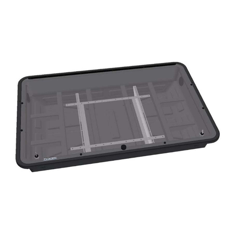
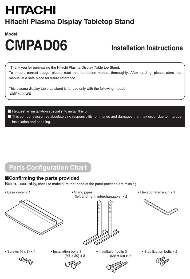
Protective Enclosures Company The V Shield Pro Lite User manual

1
PRO
277 Douglas Avenue, Suite 1012
Altamonte Springs, Fl. 32714
1-800-331-2628
Save this assembly manual for future reference in the event that you need to order replacement parts.
• Owner’s Manual
• Assembly Instrucons
• Warranty Informaon
INS-A-TVSHIELDPROLITE-ENG 5/31/23 Made in the USA

2
•
•
supply the correct anchoring hardware).
• Depending on the size of the enclosure, you are likely to need one helper for this process.
PRO®
PRO®
PRO®
PRO®
•
•
reinforced.
•
•
•
•
•
•
•
product is used outdoors.
•
mishandling the enclosure.
•
®
•

3
TOOLS REQUIRED FOR INSTALLATION
These are the tools that are generally required for assembly of our products. These tools are not included with the
product purchase, nor included in the box. You will need to use the hardware from a separately sold TV wall or
ceiling mount.
Cordless Drill or Electric Drill 3/16" Drill Bit for Wood Stud Installaon or 1 / 2” Ma-
sonry Drill Bit for Concrete/Brick Wall Installaon and
for Drywall Anchors (Used Only for Sides of Enclosure)
Phillips Screw Driver 7/16” Socket and Wrench
An Adult w/ an Adult Helper
Electronic Stud Finder for Drywall Applicaons Bubble Level

4
PARTS IDENTIFICATION
Included in Box
(1) The TV Shield PRO Lite®(1) Base Wall Frame (Aached to
Inside of Enclosure During Shipping)
(1) T-27 Allen Key for Pin in
Security Screws
(1) Fan Power Cord (8) ¼” x 1 ½” Lag Bolts (8) ¼” x 1 ½” Lag Shields/Concrete
Anchors
(2) ¼” Hollow Wall Anchor (6) ¼” x ¾” Security Pin in Torx
Screws (Installed in Enclosure During
Shipping)

Figure A
Frame
Figure A
STEP 1: Remove Security Screws
*Read all of the assembly notes, cauon noces and important informaon prior to starng
the installaon.
STEP 2: Base Frame Installaon
Screw
Screw
* Skip this secon and connue to Step 2, opon B if you are installing
the enclosure on a concrete or brick wall.
The cutout in the base frame is where you will pass any cables through. The enclosure can be oriented
with the fan at the top or the boom depending on your installaon and power locaon (in other words,
the unit can be ipped for installaon if needed). The fan locaon will be opposite of the cable pass-through.
Placing
Figure A
Figure B
Figure C
Figure B
Figure C
InstallInstall

6
Figure A Enclosure
STEP 4: Enclosure Installaon
page 7).
You may need to li the enclosure to line it up. Do not ghten them
all the way yet (see Figure B).
STEP 3: TV Installaon
Be sure to check your total TV depth from the wall with the mount
and make sure it is less than the max interior depth of the enclosure. You
may need to use a low prole mount for installaons where the TV is more
than 2.5”.
Figure A
STEP 5: Removal of Protecve Film & Cleaning
Screws
Step 4:
enclosure is kept like new.
Figure B
Step 4:
Figure C

7
recommended to preserve the appearance of the unit.
clean water rinsing.
PRO®www.thetvshield.com)
When the solvent will not penetrate the scker material, apply heat (hair dryer) to soen the adhesive and promote
removal (GASOLINE SHOULD NOT BE USED).

8
PRO®
•
•
•
•
•
cleaned regularly.

PRO
PRO
PRO
manufactures defects.
or design or pay the purchaser a sum for the then fair market value of the product, considering the amount of
PRO

10
product.
Shield PRO
PROPRO
277 Douglas Avenue, Suite 1012
Altamonte Springs, Fl. 32714
USA

11
PRO
PRO
PRO
PRO
PROPRO
277 Douglas Avenue, Suite 1012
Altamonte Springs, Fl. 32714

12
277 Douglas Avenue, Suite 1012
Altamonte Springs, Fl. 32714
1-800-331-2628
Table of contents
Other Protective Enclosures Company TV Accessories manuals
Popular TV Accessories manuals by other brands
Loewe
Loewe floor stand motor s.77 Assembly instructions
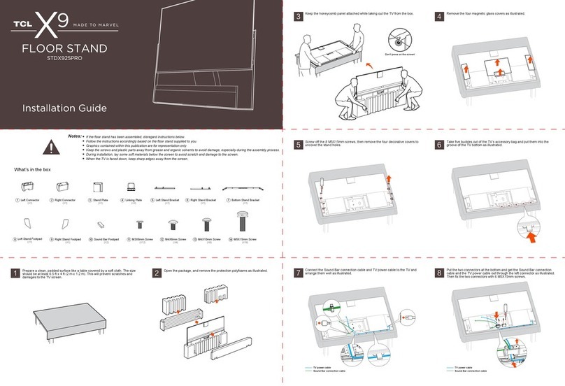
TCL
TCL X9 installation guide
Panasonic
Panasonic TY56LC16F1 - TELEVISION STAND - MULTI-LANG instructions
SMC Networks
SMC Networks EZ Connect Antenna Ceiling Box Kit Installation & user guide
Grundig
Grundig P37-844 FR Service manual
Safco
Safco 8933 Assembly instructions
