9 10
11 12
13
15
14
16
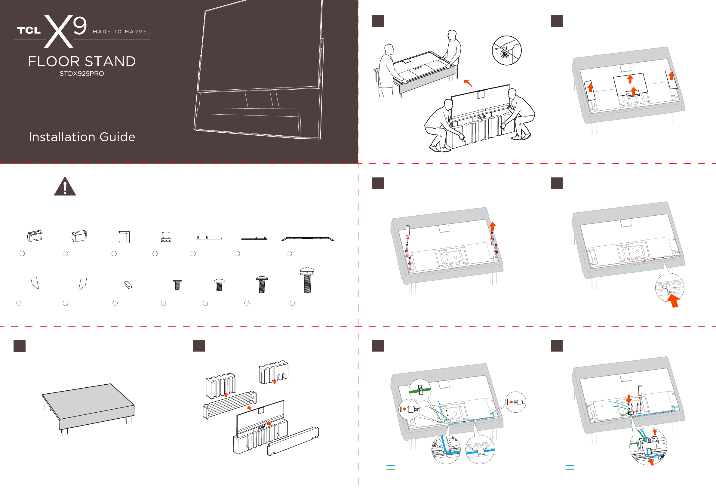
1
2
1
2
Remove the magnetic glass cover of the Subwoofer, align the Subwoofer with
the screw holes in the connectors and secure the Subwoofer to the connectors
with 8 M5X15mm screws as illustrated.
Align the left and right stand brackets on the back of the TV and secure
them to the TV with 8 M5X15mm screws.
Plug in the Subwoofer power cable, and let the TV power cable and the Sound
Bar connection cable go through the groove as illustrated.
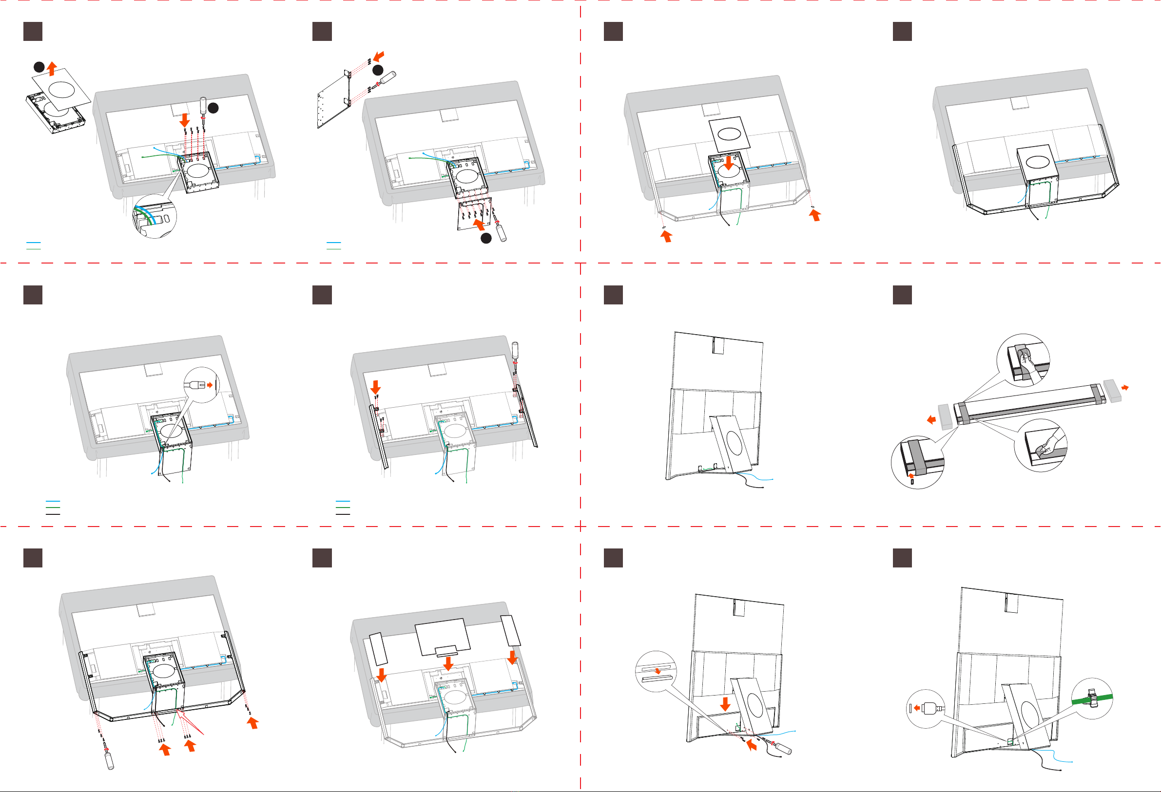
Fix the linking plates on the two ends of the one side of the stand plate
with 6 M3X6mm screws as illustrated in
Figure
1
. Then secure the stand
plate to the Subwoofer with 12 M5X15mm screws as illustrated in
Figure
2
.
Put back the magnetic glass cover of the Subwoofer, and stick the footpads
on the two ends of the bottom stand bracket.
17 Lift the TV upright.
20 Plug the Sound Bar connection cable to the port on the Sound Bar.
All installation is now completed.
18 Peel the tape and film off the Sound Bar as illustrated, then stick the
two footpads on the two ends of the bottom of the Sound Bar.
Installation of the floor stand is done.
Sound Bar connection cable
TV power cable
Sound Bar connection cable
TV power cable
Subwoofer power cable
Sound Bar connection cable
TV power cable
Subwoofer power cable
Sound Bar connection cable
TV power cable
M4*10
M3*6
19 Remove the rubber plugs on the bottom of the Sound Bar, then match the
Sound Bar with the linking plates and fix them with 4 M4X6mm screws.
Secure the two ends of the bottom stand bracket to the left and right stand
brackets with 6 M4X10 screws. Secure the middle part of the bottom stand
bracket to the stand plate with 6 M3X6mm screws. Refer to the illustration
below.
Put back the four magnetic glass covers as illustrated.
Note: Keep the Sound Bar connection
cable between the stand plate
and the bottom stand bracket.
Note: Before securing the Subwoofer,
get the two cables out through
the Subwoofer.