PROTRAKKER 400DB User manual
REV 1
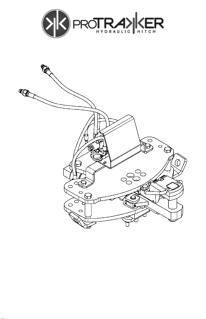
400DB HYDRAULIC HITCH
OWNER’S MANUAL

Page 2
REV 1 www.proTrakker.com

Page 3
REV 1 www.proTrakker.com
Table of Contents
Specifications........................................................................4
Contacting the Company ......................................................4
Safety Instructions ................................................................5
Maintenance .........................................................................6
Troubleshooting....................................................................7
Installation Instructions .........................................................8
Manual Hitch Operation ......................................................21
Parts Diagram: 400DB ASSEMBLY....................................22
Parts Diagram: 400DB DRAWBAR ASSEMBLY.................24
Parts Diagram: 400DB VALVE & COVER...........................26
Parts Diagram: MANIFOLD ASSEMBLY ............................28
Parts Diagram: CAB CONTROL ASSEMBLY.....................29
Protrakker™ Hydraulic Hitch Quick Reference Guide.........30

Page 4
REV 1 www.proTrakker.com
Specifications
Hydraulic Requirements:
Single Hydraulic Outlet, Continuous Duty
Flow Rate: 1.5 gpm
Pressure Range: 2250-3000 psi
Electrical Requirements:
Maximum Current: 3.5 amps
Voltage Range: 9-16 Volts DC
Capacity and Performance:
Maximum Vertical Load: 10,000 lbs
Power Rating: Up to 400 HP
Left/Right Travel: 26 inches
Standards and Limitations:
Not for use with PTO drive-line powered equipment
Contacting the Company
MBW
122 North Des Moines Street
Odebolt, Iowa 51458
U.S.A.
Toll Free: 877.568.4240 (Monday –Friday, 7:30AM –5:30PM U.S. CST,
Saturday 7:30AM –12:00PM U.S. CST)
Local/International Phone: 1.712.668.4240
Fax: 1.712.668.2311 (24 hours, 7 days/week)
Email: cory@mbwproducts.com
Website: www.proTrakker.com or www.mbwproducts.com

Page 5
REV 1 www.proTrakker.com
Safety Instructions
Read and understand the information in this manual
before installing or operating this system.
Inspect this system for damage and/or wear before
every operation. Replace any damaged or worn
components before using.
Never work alone.
Never operate this system with guarding removed.
When preparing to install or maintain this system, the
tractor wheels need to be blocked to prevent
movement and any jacks or lifts used should be
appropriate for the weight to be lifted, stable and in
good condition.
Hydraulic lines should be inspected for wear and
cracks. Any indication of damage to these lines
should be immediate grounds for replacement of the
line.
Caution should be taken when working on hydraulic
systems. Ensure all pressure in the system is relieved
properly and that the fluid is cool before loosening any
fittings or removing lines.
Use appropriate personal protective equipment (PPE)
when performing maintenance on hydraulic systems,
such as safety glasses with approved side shields,
heavy leather work gloves, and coveralls or an apron.
The tractor 3-point may settle during operation. Be
sure to check and apply chain tension by ‘bumping’
up the 3-point often.
Page 6
REV 1 www.proTrakker.com
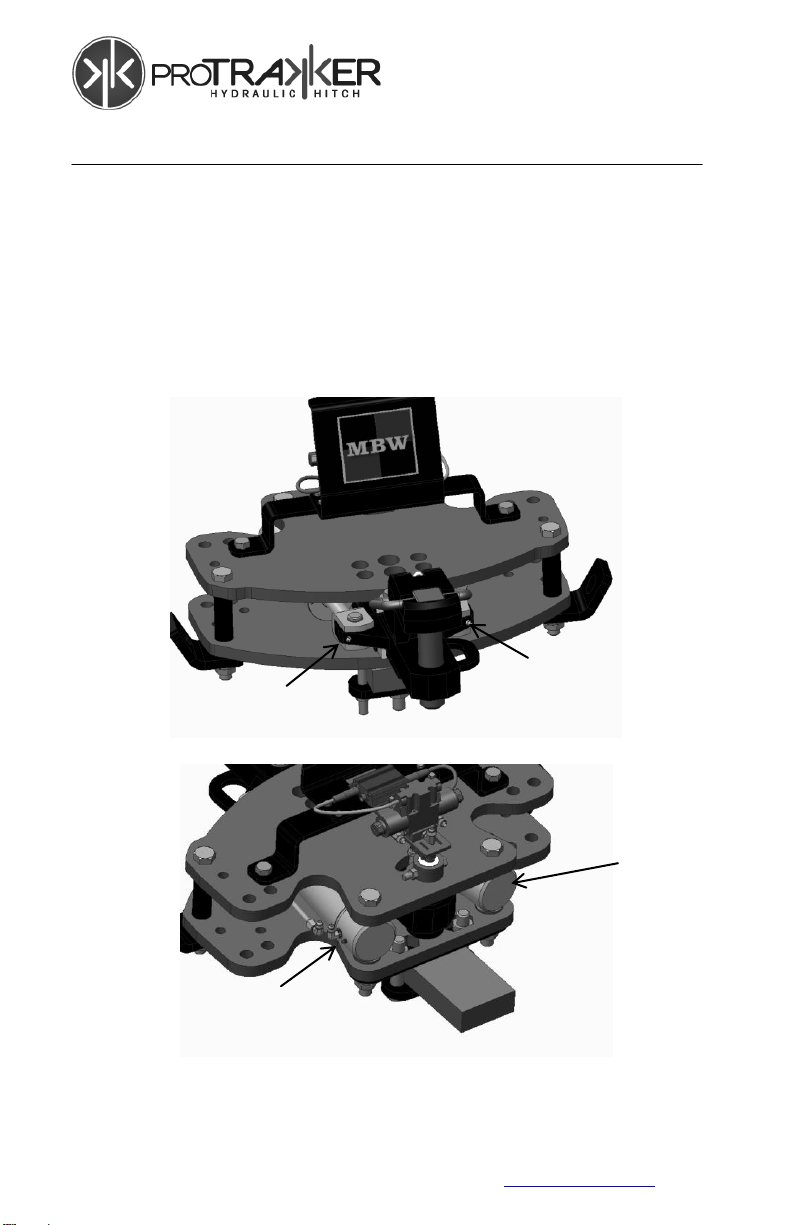
Maintenance
Initial Installation: After the first few hours of operations,
check the tightness of all hardware. Substantial wear will
occur to the product and implement if fasteners and
hardware are not properly secured.
Grease Fittings: Proper lubrication of the 4 grease
locations at 12-hour intervals will dramatically prolong the life
of the product.
Bolts: If the 1” bolts become loose for any reason, they must
be tightened to 580 ft-lbs. Check the bolts periodically.
2
1
3
4

Page 7
REV 1 www.proTrakker.com
Troubleshooting
Problem: The hydraulic hitch does not move
The tractor hydraulics are
not active.
Make sure the hydraulic hoses are
hooked up correctly (line labeled
pressure; the other line return).
Poor electrical connection.
Check indicator lights on the hydraulic
block coil connectors. If no light, check
cable connections. If lights show, then
replace the coil.
Problem: The hydraulic hitch moves the wrong direction
The tractor hydraulics are
reversed
Make sure the hydraulic hoses are
hooked up correctly (line labeled
pressure; the other line return).
Problem: The hydraulic hitch seems very “jerky” and seems to
“hunt” when the tractor is at a standstill.
The hydraulic flow is too
fast
Turn the oil flow way down. The slower
the hitch moves, the better it will
perform.
If your tractor hydraulics will not turn
down far enough, MBW offers a needle
valve to put inline.
Too much 3-point
movement
Tighten up drawbar and/or 3-point slap.
When the hitch stops it will sense any
looseness or slop and a chain reaction
will occur.

Page 8
REV 1 www.proTrakker.com
Installation Instructions
Tractor Preparation
Before installing the 400DB, park the tractor on a smooth
level floor with adequate clearance to work around the
drawbar area.
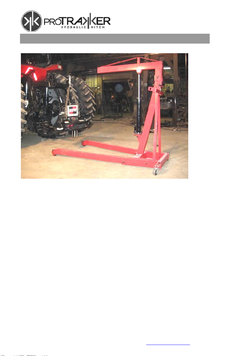
Hitch Preparation
Use a lift or hoist to lift the 400DB assembly.
If the tractor is equipped with a drop-style drawbar, be sure
that the drop is down. The Protrakker Hydraulic Hitch
requires a minimum mounting clearance of 14 1/4 inches
between the center of the draw-pin hole and rear of the
tractor support casting.
WARNING!
Installation of this system will change the leverage on the rear
of the tractor. Some implement/tractor combinations may
require added weight to the front of the tractor to improve
handling. Test the steering performance of the tractor with the
implement in all configurations before use and add weight if
needed. Review your tractor’s specifications for instructions
and limitations.

Page 9
REV 1 www.proTrakker.com
Mounting Hardware
ITEM
PART #
DESCRIPTION
QTY Provided
1
B10-400DB
BOLT 1 X 6
1
2
B12-400DB
BOLT 1 X 5
2
3
B13
BOLT 3/4 X 6
2
4
MB15-400DB
CLAMP PLATE 3/4 IN THICK
3
5
MB32-400DB
CLAMP PLATE 1/2 IN THICK
3
6
MB33-400DB
CLAMP PLATE 1/4 IN THICK
2
7
MB40-400DB
REAR CLAMP PLATE
1
8
MB81-400DB
SPACER BUSHING
1
9
N6
LOCKNUT 3/4
2
10
W5
1IN LOCKNUT NC
1
11
W8
1IN NUT NF G9
2
CH1
DRAWBAR SUPPORT CHAINS (not shown)
2

Page 10
REV 1 www.proTrakker.com
Determine Proper Mounting Configuration
Note: The mounting hardware included with the ProTrakker
unit is compatible with common straight or offset drawbars.
Not all hardware will be used. Some drawbars may require
additions or modifications to the hardware to allow the unit to
be properly mounted. Contact MBW if you are not certain if
your drawbar is compatible with the hardware provided.
Different combinations of
supplied spacer plates
will be used depending on
offset in tractor drawbar.
Example: ¾ & ½ inch
thick spacers used with a
1 ¼ offset drawbar
Spacer plates used to
ensure the hitch is level
after installation.
A wedge spacer is available for
mounting to sloped drawbar
surfaces. Contact MBW if Wedge
is required. The wedge may
need to be modified to match
the drawbar slope.
The drawbar spacer
bushing is inserted into
the drawbar hole.

Page 11
REV 1 www.proTrakker.com
Protrakker Hydraulic Hitch Preparation:
Drop both Hex Nuts
into the front of the
Protrakker Hitch.

Page 12
REV 1 www.proTrakker.com
Ensure you have the proper spacer plates positioned on the
tractor drawbar correctly. Use a straightedge as shown to
figure out how many spacer plates you need. Note: Straight
tractor drawbars will not require spacer plates in-between
Protrakker Hitch and tractor drawbar, but will be needed on
the bottom side of the tractor drawbar to properly space
bolts.
Drop all three bolts
into rear of the
Protrakker Hitch
Page 13
REV 1 www.proTrakker.com
Mounting the Protrakker Hydraulic Hitch
Using a forklift or chain hoist, position the Protrakker
Hydraulic Hitch over the tractor drawbar as shown. Center
the Protrakker Hitch directly over the tractor drawbar with the
draw-pin hole lined up over the center or the corresponding
Protrakker Hitch mounting hole. Carefully lower the
Protrakker Hitch down ensuring all bolts and spacers fall into
place.

Page 14
REV 1 www.proTrakker.com
Install Hammerstrap at Front of Drawbar
Note: The mounting hardware included with the ProTrakker
unit is compatible with common straight or offset drawbars.
Some drawbars may require additions or modifications to the
hardware to allow the unit to be properly mounted. Contact
MBW if you are not certain if your drawbar is compatible with
the hardware provided.
Install 3/4” thick hammer strap clamp (F) and spacer bushing
(G) underneath tractor drawbar and secure with 3/4” flanged
nuts (D).
D
F
G

Page 15
REV 1 www.proTrakker.com
Install Hammerstrap at Rear of Drawbar
With the rear Protrakker Hitch bolts secured, slide
underneath of hitch and install front Protrakker Hitch
hammerstrap (F). Carefully thread the bolts (B) into hex nuts
(C) at the front of the Protrakker Hitch.
BE SURE THE HAMMERSTRAP CLAMP IS LEVEL WITH
THE HITCH. THE WEDGE CLAMP OR OTHER
MODIFICATIONS MAY BE NEEDED IF POSITIONED ON
THE SLOPE OF THE TRACTOR DRAWBAR.
F
B
C

Page 16
REV 1 www.proTrakker.com
4 Inch Wide Drawbars
4 inch wide drawbars will require the 1¾” OD and 2” OD
spacer bushings to eliminate gap between the bolts and
drawbar.
1¾” OD
BUSHING
2” OD
BUSHING
4” WIDE
DRAWBAR
Inspect the installation to
ensure there is minimal gap
between the bolts or bushings
and the drawbar. If your
drawbar width is not
accommodated by bolt
positions and bushings,
contact MBW for special
components.
Page 17
REV 1 www.proTrakker.com
Tighten Mounting Hardware
With all the hardware in place, remove chain hoist and
tighten 3/4” bolts and nuts to a torque 350 foot pounds and
1” bolts to a torque of 580 foot pounds.
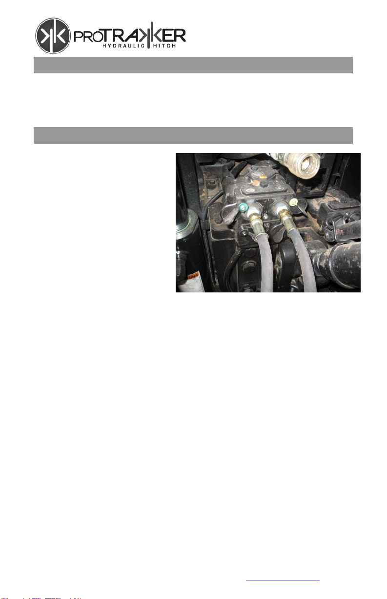
Connect Hydraulic Hoses
Connect the supply lines
to the tractor remote
outlets so that the line
labeled pressure line is
pressure and the other
line being return.

Page 18
REV 1 www.proTrakker.com
Install Drawbar Stabilizer Chains
With the two-point of the tractor in the complete raised
position, loop the chain through the drawbar stabilizer chain
brackets located on each side of the Protrakker Hitch and
over the tractor two-point as shown.
Hook the chains as tight as possible. With chains hooked,
lower the tractor’s two-point approximately six inches and
tighten each chain one more link only. Raise the two-point
up and tie-up excess chain.
WARNING
CHAINS MUST BE INSTALLED AS INSTRUCTED.
FAILURE TO PROPERLY INSTALL STABILIZER
CHAINS COULD RESULT IN SERIOUS INJURY AND
DAMAGE TO EQUIPMENT
WARNING
HYDRAULIC DRIFT WILL CAUSE SLACK IN THE
SAFETY CHAINS. ALWAYS CHECK FOR HYDRAULIC
DRIFT ON THE 3-POINT SYSTEM BEFORE USING
THE DRAWBAR. CHECK FOR DRIFT OFTEN WHILE
USING THE DRAWBAR.
Stabilizer Chain
Brackets
Page 19
REV 1 www.proTrakker.com
Be sure the tractor drawbar remains down on the support
casting. Chains are made to help stabilize the drawbar, and
not made to carry the entire load.
Mounting the Console
The RAM Mounting System provided
gives you many options for mounting
your console. It fits many different sizes
of monitor bars inside the tractor cab.
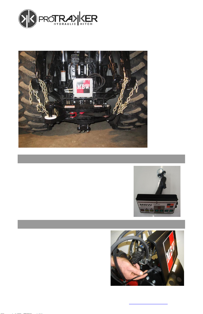
Install Power and Control Cables
Install the four-pin cable to the
control box on the Protrakker
Hitch. Carefully route the four-
pin cable up to the tractor cab.
Install the four-pin connector to
the console and then install the
remaining two-pin power cable.

Page 20
REV 1 www.proTrakker.com
Route the power cable to a reliable 12-volt supply. We
recommend going directly to the battery.
Red wire = positive
Black wire = negative
Powering Up
With the control console in the off
position, start up the tractor. Lock the
correct hydraulic lever into place and
turn console to manual mode. Using
left and right jog button, observe the
indicator and hitch moving. Switch to
auto mode and take tractor to a hillside
to observe auto mode working. Note:
If these modes are not working
properly switch around the
pressure and return lines.
Manual Mode: This function enables
the operator to move the hitch left or
right by using the jog switch.
Auto Mode: This function enables the hitch to sense side
hill slope and automatically compensates to establish level
reference value.
Gain Function: This enables the operator from the cab to
adjust the Hitch travel more or less per degree of slope.
This is particularly useful when switching to implements with
different pin to axle lengths.
GPS Ready Models: Follow steps 1-7 for mounting
instructions.
GPS wiring harness will be plugged into the Protrakker’s
position sensor cable. All further set-ups will be done by your
GPS provider.
Table of contents


