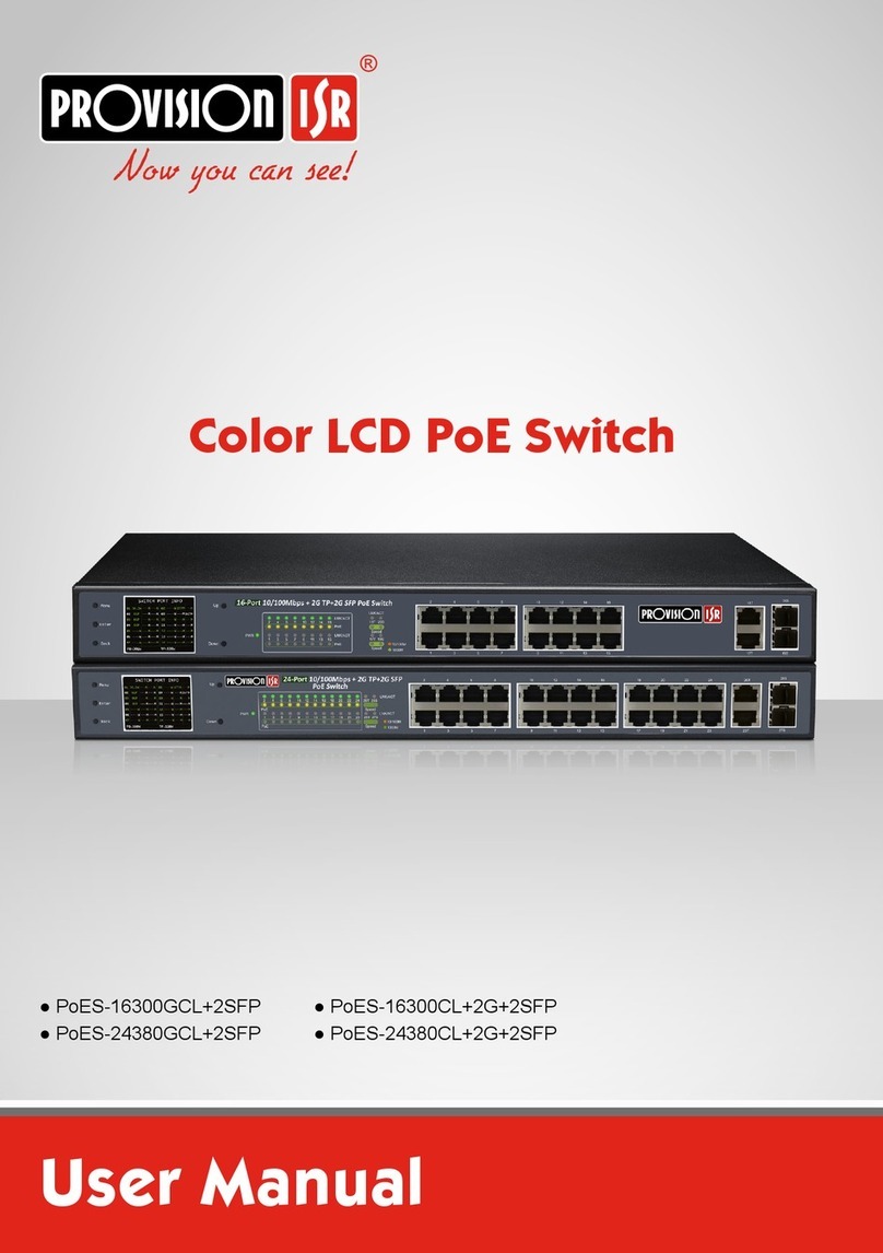
Provision ISR PoES-16250CL+2G+2SFP User manual

User Manual
Color LCD PoE Switch
●PoES-16250GCL+2SFP
●PoES-24370GCL+2SFP
PoES-16250CL+2G+2SFP
PoES-24370CL+2G+2SFP

Page | 2 COLORLCDPOESWITCHUSERMANUAL
Notes
Beforeoperatingtheswitch,westronglyadviseuserstoreadthismanualandkeepitfor
lateruse.
Pleaseusethesuppliedpowercord.
Avoidincorrectoperation,shock,vibrationorheavypressingwhichcancausedamageto
theswitch.
Donotusecorrosivedetergenttocleanthebodyoftheswitch.Ifnecessary,pleaseusea
softdryclothtowipedirt;forhardcontamination,useneutraldetergent.Anycleanserfor
high‐gradefurnitureisapplicable.
Donotoperatetheswitchinextremetemperaturesorextremehumidityconditions.
Keepawayfromheatsourcessuchasradiators,heatregisters,stove,etc.
Theinstructionsinthismanualcouldbeoutdated;ifyouneedanyclarificationsyoucan
contactanauthorizedPROVISION‐ISRtechnician.PROVISION‐ISRreservestherighttoadd
changestothismanualandpublishitonlineonourwebsite(www.provision‐isr.com):there
maybeinconsistencieswiththelatestversion.Thisappliestoanyandallsoftwareupgrades
andproductimprovements,interpretationandmodificationadded.Thesechangeswillbe
publishedinthelatestversionwithoutpriornotification.
Allpicturesandexamplesusedinthemanualareforreferenceonly.
PackageContents
Checkthefollowingcontentsofyourpackage:
PoESwitch x1
User’sManual x1
PowerCord x1
Accessories(Rackmountears*2,RubberFeet*4,Bracketscrews*8)
Ifanypartislostanddamaged,pleasecontactyourlocalagentimmediately.

Page | 3 COLORLCDPOESWITCHUSERMANUAL
TableofContents
1) Introduction................................................................................................................4
2)
HardwareDescription
.............................................................................................4
2.1)
FrontPanel:
........................................................................................................4
2.2) RearPanel.............................................................................................................5
3) LCDFeatures:
...........................................................................................................6
3.1)
GeneralStatusIndicators:
................................................................................6
3.2)
GeneralWarnings:
.............................................................................................6
3.3)
PortStatusWarnings:
.......................................................................................7
3.4)
MenuandOperations:
......................................................................................7
3.4.1. SwitchMode:........................................................................................................7
3.4.2. PortBandwidthLimit:...........................................................................................8
3.4.3. PDType:................................................................................................................8
3.4.4. KeepAlive:............................................................................................................8
3.4.5. PSEPowerAdjust:.................................................................................................9
3.4.6. PSEPortPriority:..................................................................................................9
3.4.7. PSEPortCondition:.............................................................................................10
3.4.8. PoEPortPower:..................................................................................................10
3.4.9. LCDState:...........................................................................................................11
3.4.10.FanControl:........................................................................................................11
3.4.11.DefaultSettings:.................................................................................................11
3.4.12.About:.................................................................................................................12
4) SwitchInstallation:
................................................................................................12
4.1)
DesktopInstallation:
.......................................................................................12
4.2)
RackMountInstallation
..................................................................................13
4.3)
Turningontheswitch
.....................................................................................14

Page | 4 COLORLCDPOESWITCHUSERMANUAL
1) Introduction
Thank you for choosingProvision‐ISR’s PoE Switch. The 16/24GE(PoE)+2GSFPLCD
DisplayPoE switchhave16(24)‐10/100/1000MbpsPoERJ45Portand2‐GigabitSFPSlot.Its
PoEports canautomaticallydetectandsupply power withthose IEEE802.3af/atcompliant
PoweredDevices(PD).Theelectricalpoweristransmittedalongwithdatainonesinglecable
allowingyoutoexpandyournetworkwheretherearenopowerlinesoroutlets,whereyou
wishtofixdevicessuchasAP,IPCamerasorIPPhones,etc.
TheLCDcanbeusedtodisplaythePoEworkstatus,accuratemeasurementtotalload
andforeachportindependently.Thiscanhelptheinstallerandengineertoquicklydiscover
andsolvenetworkfailuresandimproveworkefficiencyandquality.
PortFeature
Model PoEPorts PoEPortsSpeed UplinkPorts UplinkPortsSpeed
PoES‐16250GCL+2SFP 16(1‐16) 10/100/1000Mbps 2SFP(17‐18) 10/100/1000Mbps
PoES‐24370GCL+2SFP 24(1‐24) 10/100/1000Mbps 2SFP(25‐26) 10/100/1000Mbps
PoES‐16250CL+2G+2SFP 16(1‐16) 10/100Mbps 2SFP+2RJ‐45
(17‐20)
10/100/1000Mbps
PoES‐24370CL+2G+2SFP 24(1‐24) 10/100Mbps 2SFP+2RJ‐45
(25‐28)
10/100/1000Mbps
2)
HardwareDescription
2.1)
FrontPanel:
TheFrontPanelofthePoESwitchconsistsofEthernetPorts,LCDDisplay+controlsandLED
indicators.
Giga(10/100/1000MbpsSwitches)Frontpanelillustration.
8.4
01
W
‐‐‐M631M
ULP
02 ‐‐‐M921M
OLP
03 ‐‐‐M‐‐‐M
SCP04 125M‐‐‐M
2.2W05 ‐‐‐M‐‐‐M
23.706 W ‐‐‐M‐‐‐M
16.807 W ‐‐‐M‐‐‐M
13.408 W ‐‐‐M920M
18.909 W 856M856M
‐‐‐‐10 W 238M238M
11 OFF ‐‐‐M‐‐‐M
23.312 W 323M323M
5.813 W 983M983M
7.314 W 223M223M
GeneralInformation
MenuControls
LEDIndicators PoEDownlinkPorts SFPUplink
Ports
LCD Monitor

Page | 5 COLORLCDPOESWITCHUSERMANUAL
10/100MbpsSwitchesFrontpanelillustration.
LEDindicators
LED Color Function
PWR Green
O
ff
:Switchisoff/Nopower supply.
Light:Theswitchison.
LNK/ACT
Orange
O
ff
:Nodevice isconnected tothe correspondingport.
Light:Indicatesthelinkthroughthatportissuccessfullyestablishedat
10/100Mbps.
Blink:IndicatesthattheSwitchisactivelysendingor
receivingdataoverthatport.
Green
O
ff
:Nodevice isconnected tothe correspondingport.
Light:Indicatesthelinkthroughthatportissuccessfullyestablishedat
1000Mbps.
Blink:IndicatesthattheSwitchisactivelysendingor
receivingdataoverthatport.
PoE Orange
O
ff
:NoPoEpowereddevice(PD) connected.
Light:ThereisaPoEPDconnectedtotheportandpowerissupplied
successfully.
Blink:Indicatesportabnormalpowersupply.
2.2) RearPanel
TherearpanelofthePoESwitchcontainsafullrangeACinletpowersocket(100to240VAC,
50/60HZ)andagroundingscrew.IncasetheACcordisnotconnectedtoground,youmust
groundtheunitusingthegroundingscrew!
Menu
Enter
Back
19
20
17
18
19
20
8.4
01
W
‐‐‐M631M
ULP
02 ‐‐‐M 921M
OLP
03 ‐‐‐M‐‐‐M
SCP
04 125M‐‐‐M
2.2W05 ‐‐‐M‐‐‐M
23.706 W ‐‐‐M‐‐‐M
16.807 W ‐‐‐M‐‐‐M
13.408 W ‐‐‐M920M
18.909 W 856M856M
‐‐‐‐10 W 238M238M
11 OFF ‐‐‐M‐‐‐M
23.312 W 323M323M
5.813 W 983M983M
7.314 W 223M223M
GeneralInformation
MenuControls
LEDIndicators PoEDownlinkPorts SFP + RJ45
UplinkPorts
LCD Monitor
ACPowerPort
GroundConnection

Page | 6 COLORLCDPOESWITCHUSERMANUAL
3) LCDFeatures:
ThisPoEswitchlineisequippedwithcolor LCD display and PoE. The LCD can display the statusof
theswitchaswellasindependentstatusforeachofthePoE portssuch as: Output power,Overload,
Shortcircuit,Lightload,Lowvoltage,Overvoltage,HightemperatureEtc.
3.1)
GeneralStatusIndicators:
1) PortNumber.Remainingportswillbedisplayedinthe
nextpage.
2) Portpowerconsumption
3) Portdownloadreal‐timebandwidth.
4) Portuploadreal‐timebandwidth.
5) PB:thetotal“PoEbudget”oftheswitch
6) TP:“Totalpower”undercurrentuse
7) PD:Numbersof“PDdevice”
8) Norm: Work mode. “Norm” for normal, VLAN and
CCTVavailable
3.2)
GeneralWarnings:
Problem:PowersupplyfailureProblem:HighACvoltageinput Problem:LowACvoltageinput
Result:Switchrestart Result:Portsareofftopreventdamage Result:Portsareofftopreventdamage
General Information
‐‐‐‐01 W ‐‐‐M‐‐‐M
‐‐‐‐02 W ‐‐‐M‐‐‐M
‐‐‐‐W03 ‐‐‐M‐‐‐M
‐‐‐‐W04 ‐‐‐M‐‐‐M
‐‐‐‐W05 ‐‐‐M‐‐‐M
‐‐‐‐06 W ‐‐‐M‐‐‐M
‐‐‐‐07 W ‐‐‐M‐‐‐M
‐‐‐‐08 W ‐‐‐M‐‐‐M
‐‐‐‐09 W ‐‐‐M‐‐‐M
‐‐‐‐10 W ‐‐‐M‐‐‐M
‐‐‐‐11 W ‐‐‐M‐‐‐M
‐‐‐‐12 W ‐‐‐M‐‐‐M
‐‐‐‐13 W ‐‐‐M‐‐‐M
‐‐‐‐14 W ‐‐‐M‐‐‐M
WARNING!
PSEfailure.
Restarting∙∙∙
PD:0PB:380W TP:0.0W Norm
General Information
‐‐‐‐01 W ‐‐‐M‐‐‐M
‐‐‐‐02 W ‐‐‐M‐‐‐M
‐‐‐‐W03 ‐‐‐M‐‐‐M
‐‐‐‐W04 ‐‐‐M‐‐‐M
‐‐‐‐W05 ‐‐‐M‐‐‐M
‐‐‐‐06 W ‐‐‐M‐‐‐M
‐‐‐‐07 W ‐‐‐M‐‐‐M
‐‐‐‐08 W ‐‐‐M‐‐‐M
‐‐‐‐09 W ‐‐‐M‐‐‐M
‐‐‐‐10 W ‐‐‐M‐‐‐M
‐‐‐‐11 W ‐‐‐M‐‐‐M
‐‐‐‐12 W ‐‐‐M‐‐‐M
‐‐‐‐13 W ‐‐‐M‐‐‐M
‐‐‐‐14 W ‐‐‐M‐‐‐M
WARNING!
HighACVoltage.
Allportsoff.
PD:0PB:380W TP:0.0W Norm
General Information
‐‐‐‐01 W ‐‐‐M‐‐‐M
‐‐‐‐02 W ‐‐‐M‐‐‐M
‐‐‐‐W03 ‐‐‐M‐‐‐M
‐‐‐‐W04 ‐‐‐M‐‐‐M
‐‐‐‐W05 ‐‐‐M‐‐‐M
‐‐‐‐06 W ‐‐‐M‐‐‐M
‐‐‐‐07 W ‐‐‐M‐‐‐M
‐‐‐‐08 W ‐‐‐M‐‐‐M
‐‐‐‐09 W ‐‐‐M‐‐‐M
‐‐‐‐10 W ‐‐‐M‐‐‐M
‐‐‐‐11 W ‐‐‐M‐‐‐M
‐‐‐‐12 W ‐‐‐M‐‐‐M
‐‐‐‐13 W ‐‐‐M‐‐‐M
‐‐‐‐14 W ‐‐‐M‐‐‐M
WARNING!
LowACVoltage.
Allportsoff.
PD:0PB:380W TP:0.0W Norm

Page | 7 COLORLCDPOESWITCHUSERMANUAL
3.3)
PortStatusWarnings:
OLP(OverloadProtection):
Theportisoverloaded
andwasshutdown.
ULP(UnderloadProtection):Theportisconsuming
extremelylowpowerwhichmightindicateafaultand
thereforetheporthasshutdown.
SCP (Short‐Circuit Protection): The port appears to
beshort‐circuitedandwasshutdown
OFF:Portnotinuse
3.4)
MenuandOperations:
Clickandholdthemenubuttonfor5secondinordertoaccessthemainmenu:
Scrollthemenuusingthe“Up”and“Down”buttons,confirmusingthe“Enter”buttonandcancel/go
backusingthe“Back”button.
Themainmenucontains12options.Thenextchapterwillgothroughit.
3.4.1. SwitchMode:
TheColorLCDPoEswitchseriessupport3workingmodes:
1) Normal:TheswitchoperatesasanormalIEEE802.af/at
PoEswitchinstandardoperationmode.
2) FixedVLAN:Thiswillenableapre‐madeVLANsettings
thatwillpreventthedownlinkportsfromany
communicationsbetweenthemselves.TheVLAN
enhancessecuritybypreventingunauthorized
connectiontoanyavailableporttocommunicatewith
theIPcamerasandotherequipmentconnectedtothe
switch.Itwillalsooptimizenetworktraffic.
8.4
01
W
‐‐‐ M631 M
ULP
02 ‐‐‐ M921M
OLP
03 ‐‐‐ M‐‐‐ M
SCP04 125 M‐‐‐ M
2.2W05 ‐‐‐ M‐‐‐ M
23.706 W ‐‐‐ M‐‐‐ M
16.8
07 W ‐‐‐ M‐‐‐ M
13.408 W ‐‐‐ M920 M
18.909 W 856 M856 M
‐‐‐‐10 W 238 M238 M
11 OFF ‐‐‐ M‐‐‐ M
23.312 W 323 M323 M
5.8
13 W 983 M983 M
7.314 W 223 M223 M
Switch Port Information
8.4
01
W
‐‐‐ M631 M
ULP
02 ‐‐‐ M921M
OLP
03 ‐‐‐ M‐‐‐ M
SCP04 125 M‐‐‐ M
2.2W05 ‐‐‐ M‐‐‐ M
23.706 W ‐‐‐ M‐‐‐ M
16.8
07 W ‐‐‐ M‐‐‐ M
13.408 W ‐‐‐ M920 M
18.909 W 856 M856 M
‐‐‐‐10 W 238 M238 M
11 OFF ‐‐‐ M‐‐‐ M
23.312 W 323 M323 M
5.8
13 W 983 M983 M
7.314 W 223 M223 M
General Information
SwitchMode
Options:
Normal
FixedVlan
CCTVMode
<
<UP>/<Down>:Select
<Enter>:Confirm<Back>:Retur

Page | 8 COLORLCDPOESWITCHUSERMANUAL
3) CCTVMode:CCTVmodewillenable“FixedVLAN”togetherwithrestrictingthedownlinkport
bandwidthto10Mbpsduplexcommunication.TheCCTVmodeallowstheinstallertoreach
distancesofupto250moverstandardCat.5ecable.
3.4.2. PortBandwidthLimit:
Thisfeatureallowsyoutomonitorandrestricttheincoming
bandwidthcomingfromasingleport.Oncecrossed,theswitch
willsetabuzzeralarmtowarnforbandwidthoveruse.Once
enabled,thissettingwilltakeeffectonalldownlinkports.It
cannotbesetforaspecificport.
Thedefaultsettingis“Disabled”meaningthatthereisno
bandwidthrestriction.Theotheroptionsare400Mbps,
500Mbpsand600Mbps.
3.4.3. PDType:
Thereare3typesofPD.Enhance,StandardandLegacy.
Enhance:Thedefaultsettings.Itwilldetectat/afmodesand
increasethecurrentsurgelimittotheifatstandardisused.
Standard:FullconformitywiththeIEEE802.3af/atstandards.
Legacy:ShouldbeusedifthePDdevicedoesnotcomplywith
theIEEE802.3afstandard.Theswitchwilltrytodetect
compliancewithlegacystandardsandsupplypowertothePDif
detected.Thisoperationmodeshouldnotbeusedunlessadvice
bythePDmanufacturer,asitmightsupplypowertodevicesnot
designedtoreceivePoEanddamageit.
3.4.4. KeepAlive:
KeepaliveisdesignedtodetectamalfunctionofaPDdevice
thatcausedittostopcommunicationandmakeattemptto
restoreitsconnectionbyhardrebootingitbytakingand
restoringpower.Thisfeatureisdesignedtoincreasethe
system’sreliabilityandreducemaintenancetothesystem.
TheKeepAlivecanbesetforeachofthePoEportsindividually.
Thesettingsshouldbedoneasfollows:
Port(01‐16/24):Therequiredportnumber
Status(Disabled/Enabled):TheKeepAliveStatus
Startup(60~300s):TheestimatedstartuptimeofthePDdevice.OnceaPDisconnectedtothe
specifiedport,acountdownwillcommencefromtheenteredvalue.Forexample.Ifthe“Startup”
settingwassetto180,onceaPDdevicewillbeconnectedacountdownof180secondswill
commence.Theswitchwillexpecttodetectincoming/outgoingtrafficfromthePDbeforethe
countdownreaches0.
PortBandwidthLimit
Disabled
600Mbps
400Mbps
500Mbps
<
Options:
<UP>/<Down>:Select
<Enter>:Confirm<Back>:Retur
n
Port1~Port24valid!
PDType
Enhance
Standard
Legacy
<
Options:
<Enter>:Confirm<Back>:Retu
r
<UP>/<Down>:Select
Port Status
01
PDKeepAlive
Disable
startup
180
Interval
180
PowerOff
5
<Enter>:Confirm<Back>:Retu
r
<UP>/<Down>:Select

Page | 9 COLORLCDPOESWITCHUSERMANUAL
Interval(60~300s):Theintervalistheallowedtimewithoutincoming/outgoingtrafficfromthePD.
Oncenotrafficisdetected,thecountdownwillcommenceaccordingtotheconfiguration.Ifthereis
stillnotrafficbythecountdownreaches0theswitchwillexecuteahardbootupprocedure.
PowerOff(5~60s):Thisvaluedeterminesthedurationofthepowercutfortherequiredswitch.After
thiscountdownreaches0,theswitchwillrestorepowertotheportandletthePDdevicebootand
initialize.
3.4.5. PSEPowerAdjust:
ThePSE(PowerSourceEquipment)isthemainpowersupplyunitfortheswitch.Inordertoincrease
itslifeandreliabilityitsrateisactuallyhigherthanthestatedpowerbank,butitisreservedfor
situationswherePDpowerrequirementsuddenlypeaksforashortmoment.
IncasethedevicesconnectedtotheswitchreachesthePB
limit,youcanmanuallyincreaseitandutilizemorepowerto
thePoEportsontheexpenseofthereservepower.
Thisfeaturehas4options:
1. Normal(100%)
2. Add5%(105%PB)
3. Add10%(110%PB)
4. Add15%(115%PB)
Note:InordertomakesurethatthePSEisnotoverloadedforalongtime,pleasemakesurethatthe
TPislowerthanthePB
3.4.6. PSEPortPriority:
ThePoEswitchhasapowerbank(PB)measuredinWatts(W).
PDwillrequirepowerfromthepowerbank.Thispowerwillbe
markedasTotalPower(TP).OncetheTPishigherthanthePB,
theswitchwillautomaticallyshutdownportsinordernotto
overloadanddamageitself.
PSEPortPriorityallowstheusertoconfigurethepriorityof
theports–actuallysettingorderofwhichtheportswillshut
down.
PSEPowerAdjust
Add5%(105%PB)
Add10%(110%PB)
Add15%(115%PB)
Options:
<Enter>:Confirm<Back>:Retu
r
<UP>/<Down>:Select
Note:
TPmustbelessthanPB!
<Enter>:Confirm<Back>:Retu
r
<UP>/<Down>:Select
PSEPortPriority
Port Priority
Critical01
High
Low <

Page | 10 COLORLCDPOESWITCHUSERMANUAL
Theprioritiesareasfollows:
Critical:Devicessetto“Critical”willshutdownlast
High:Devicesetto“High”willshutdownonceallthe“Low”prioritydevicesasshutdown.
LowPriority(DefaultSettings):Thesedeviceswillshutdownfirst.
3.4.7. PSEPortCondition:
Thissettingwilldeterminewhethertheswitchisallowedto
distributePoEtothespecifiedchannel.Thissettingismainly
usefulaftertheinitialsettingofthenetworkandthePD
devices.Afterthesystemisup,allportswithoutPDdevices
andallunusedportsshouldbedisabledfromreceivingPoE.It
willpreventoverloadingthesystembyunrequiredPoEdevices.
“Enable”isthedefaultsetting.
ThissettingwillonlyaffectPoEandwillnotaffectnetwork
communication.
3.4.8. PoEPortPower:
Thissettingcanlimitthepowersuppliedtoaspecificportasrequired.Eachportcanbeconfigured
independently.
1) Port:Portnumberforconfiguration.
2) Power(6‐36W):Thepowerlimitfortheport.Skipsin2Wintervals.
Note:PoEPortPowerisavailableforconfigurationonlyifthePDtypeissetto“Enhanced”/”Legacy”.
IfthePDtypeissetto“Standard”thePoEPortPowerisautomaticallysetto32Wandcannotbe
modified.
PSEPortPower
Port Power
10W01
PSEPortCondition
Port Status
Enable01
Disable
<

Page | 11 COLORLCDPOESWITCHUSERMANUAL
3.4.9. LCDState:
ThissettingwilldeterminethedurationofwhichtheLCD
monitorwillstayon.Theoptionsareasfollows:
1) Never(AlwaysOn):TheLCDmonitorwillstayon.
2) 10min(DefaultSetting):TheLCDwillturnoffafter
10minutes.
3) 20min:TheLCDwillturnoffafter20minutes.
4) 30min:TheLCDwillturnoffafter30minutes.
3.4.10. FanControl:
Thissettingwilldeterminetheswitchinternalfan
workingmode.Theoptionsareasfollows:
1) AlwaysOn:Thefanwillstayonregardlessofthe
PBstatus.
2) 20%PB(DefaultSetting):Thefanwillturnononce
thePBreaches20%consumption.
3) 40%PB:ThefanwillturnononcethePBreaches
40%consumption.
4) 60%PB:ThefanwillturnononcethePBreaches60%consumption.
3.4.11. DefaultSettings:
Usethisoptionifyouwishtoresetallswitchsettingsandconfigurationbacktofactorydefault.
Restoringsystem
settings......
DefaultSetting
DefaultSetting
FactoryDefault:
Cancel
Confirm<
<UP>/<Down>:Select
<Enter>:Confirm<Back>:Return
Fancontrol
Always
20%PB
40%PB
60%PB
On<
Options:
<UP>/<Down>:Select
<Enter>:Confirm<Back>:Retur
LCDState
Turnoffafter:
Never(AlwaysOn)<
10min
20min
30min
<UP>/<Down>:Select
<Enter>:Confirm<Back>:Retur

Page | 12 COLORLCDPOESWITCHUSERMANUAL
3.4.12. About:
ThiswillshowyougeneralinformationaboutthePoESwitch.
4)
SwitchInstallation:
ThissectiondescribeshowtoinstallyourEthernetSwitchinthebestmannerandmakeproper
connections.Pleasefollowthefollowinginstructionsinavoidofincorrectinstallationwhichmight
causedevicedamageandpotentialsecuritythreat.
GeneralInstructions:
Donotplacetheswitchnearwateroranydamparea.Preventwaterormoisturefromentering
theswitchchassis.
Donotplacetheswitchonanunstablecaseordesk.Theswitchmightbedamagedseverelyin
caseofafall.
Ensureproperventilationoftheequipmentroomandkeepthealltheventilationopeningsofthe
switchfreeofobstruction.
Makesurethattheoperatingvoltageandcurrentmatchesthepowerinputlabeledontheswitch.
Donotopenthechassiswhiletheswitchisoperatingorwhenelectricalhazardsarepresentto
avoidelectricalshock.
Beforecleaningtheswitch,unplugthepowerplugoftheswitchfirst.Donotcleantheswitch
withwetclothorliquid.
4.1)
DesktopInstallation:
Fordesktopinstallation,pleaseattachthesuppliedcushioningrubberfeetonthebottomofeach
corneroftheSwitch.Thiswillpreventtheswitchfromshiftingorslidingandwillreduceshockin
case of external vibration. Allow adequate space for ventilation between the device and the
objectsaroundit.
Thankyoufor
Model:PoES‐24380GCL+2SFP
choosingProvision‐ISR
About
HWVer.:V3.0
SWVer.:V1.20

Page | 13 COLORLCDPOESWITCHUSERMANUAL
4.2)
RackMountInstallation
Theswitchisrack‐mountableandcanbeinstalledonanyEIA‐19 compatible rack. Before
installation, pleaseinstall the mounting brackets on the switchsidepanels(oneoneachside),
securethemwiththeprovidedscrews.Donotusedifferentscrews since longer screws might
damagetheswitchcomponentsandshorterscrewsmightnotbeartheweightoftheswitchafter
installation.
Afterthebracketshasbeeninstalled,usetherackmountscrews(notincluded),inordertosecurely
mounttheswitchontherack.
Step1:Bracketinstallation

Page | 14 COLORLCDPOESWITCHUSERMANUAL
Step2:Mountingtheswitchontherack.
4.3)
Turningontheswitch
Pleaseplugthepowersupplyintotheswitch,theinternalpowersystemoftheswitchcanAuto‐
regulatetheworkingpoweraccordingtotheactualinputpower.Whentheswitchispoweron,the
powerindicatorwillbelightonthefrontpaneloftheswitchshines.
Note:Pleaseconfirmthevoltageiscorrectbeforepoweron,otherwisetheswitchwillbe
damaged.(ThereisapowersupplysocketonthebackpanelofthePoEEthernetswitch.The
powerinputis:100V‐240Vac,50/60Hz.)
This manual suits for next models
3
Table of contents
Other Provision ISR Switch manuals
Popular Switch manuals by other brands
FEDERAL PACIFIC
FEDERAL PACIFIC AUTO-JET AJS INSPECTION & MAINTENANCE RECOMMENDATIONS

Kärcher
Kärcher 6.997 Series manual
H3C
H3C S3610 Series Operation manual
NETGEAR
NETGEAR AG711F installation guide
HP
HP Aruba 6400 Series Installation and getting started guide
ANTAIRA
ANTAIRA LMP-1802G-M12-10G-SFP-67-110 Series Hardware manual
