Proworks HSP 94063TOP2 Short Course Instructions for use

PROWORKS
Construction Manual for HSP 94063TOP2 Short Course
Welcome to this assembly guide for Proworks’ construction kit version of the HSP 94063TOP2 Short
Course 1/8 RC model. The guide consists of several detailed easy-to-follow steps that will yield a fully
constructed and functional 1:8 scale RC model complete with battery pack, remote control and
charger.
The model comes packed in more than 20 bags, each one numbered and labeled with the part
numbers of the parts inside. Every construction stage will start by informing you which bags contain
the parts needed for that particular stage, so as long as you have those bags ready and keep any
parts from previously opened bags nearby, you will be able to simply follow the guide systematically
until the model is complete. During construction, it is advised you keep an orderly workstation and
use correct tools so you do not damage the model and its components. Consider carefully opening
the bags so that parts not used right away can remain in them until needed, or get a few small boxes
to keep parts in during construction. In some cases, not all parts from a bag opened in a particular
stage is used at once, and should be set aside for the next one.
Each stage consists of several steps, along with several detailed pictures. Each stage also features a
video supplement that takes you through the exact steps of the written manual in real time. Both the
video and the written guide is made to be largely independent of each other, but will certainly make
following the steps and constructing the model correctly very easy when used together. Some of the
specific assembling of the more intricate steps may be difficult to follow using only the written guide,
but the video guide does not provide as much information on each step beyond the visual.
http://www.proworks.no/file/andre/manual94063.pdf
1.0: Differential Gear Sets
Youtube guide for this stage: https://youtu.be/S3Kxp1M8brE
Requires following bags:
7:
60021 Gear Box
60045 Front/Rear Diff. Gear Set
60065 Center Diff. Gear Set
9:
60086 Countersunk Self-tapping Screw 3*10
60091 Countersunk Self-tapping Screw 3*16
61001 Chassis
61025 Countersunk Mech Screw 3*10
15:
60019 Rear Lower Susp. Arm Holder
60020 Rear Lower Susp. Arm Reinforcement Plate
60044 Adjustable Bushes
60091 Countersunk Self-tapping Screw 3*16
19:
60013 Front Lower Susp. Arm Holder
60022 Suspension Holders
60085 Countersunk Self-tapping screw 3*25
60091 Countersunk Self-tapping Screw 3*16
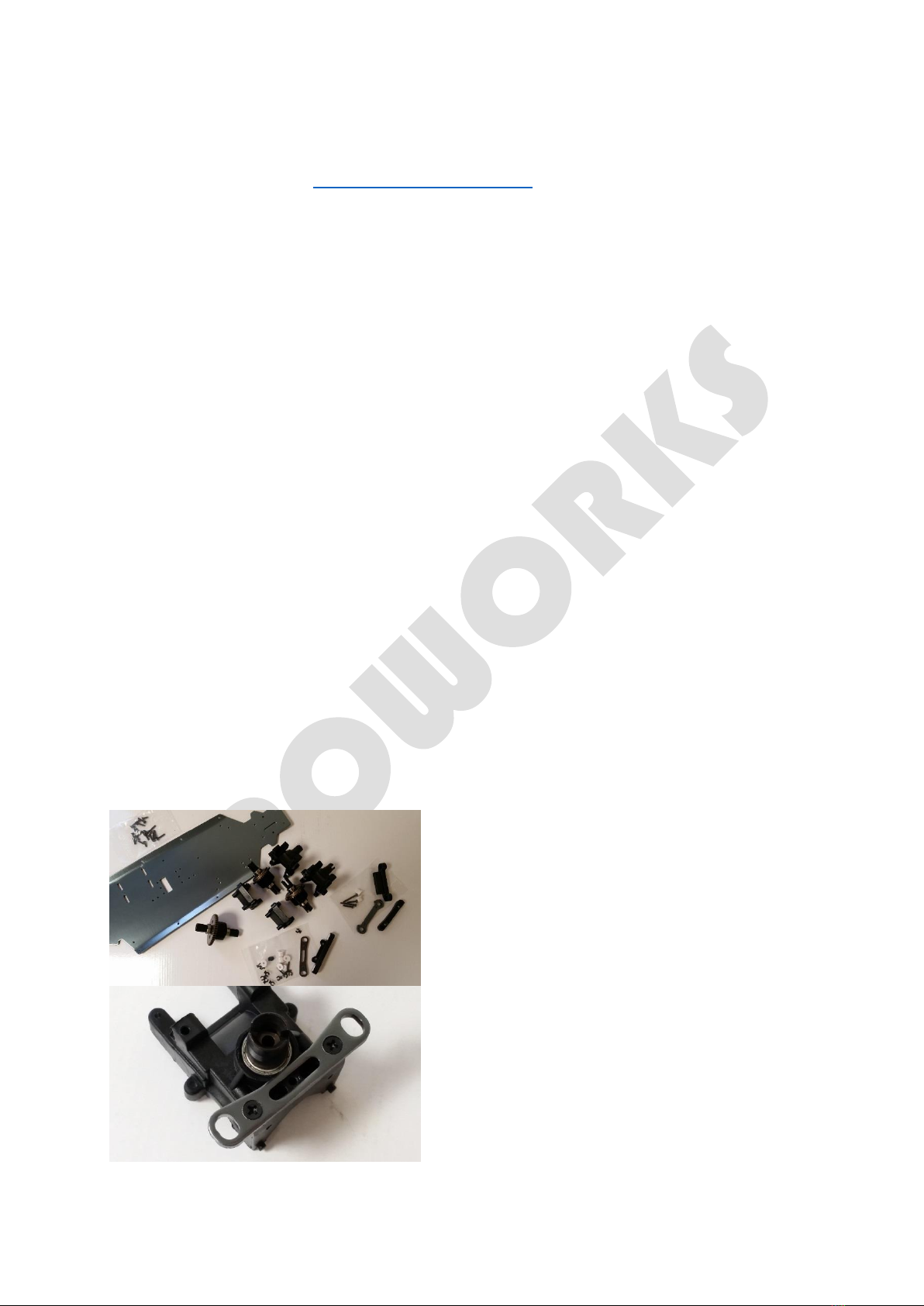
1.1: The first step will be to mount the differential Gear Sets to the chassis. To prepare for this, open
bag 7 containing Diff. Sets. You will notice two of the
differential gears are identical –these 60045
Front/Rear Diff. Gear Set- while one is unique –this is
60065 Center Diff. Gear Set-, and two Gear Boxes -
60021 Gear Box- each split into two parts. Place the
Center Diff. aside for later. Pick any of the two
identical back pieces of a Gear Box –this is the one
with a driveshaft-, open bag 15 and take the metal
piece –60020 Rear Lower Susp. Arm Reinforcement
Plate- and the two screws -60091 Screw 3*16- from
the smaller bag inside, making sure to keep the other
contents in the bag for later. Attach the metal part to
the Gear Box part just under where the driveshaft
exits the Gear Box, as shown in picture. This is the
Rear Gearbox Assembly.

1.2: Open bag 19, take the second Gear Box back piece And mount the two plastic pieces –Susp.
Holders- from bag 19 onto the Gear Box back piece as shown in picture, using the screws included.
The larger plastic piece is to be used above driveshaft
with Screws 3*25 while the smaller plastic piece is to
be used bellow driveshaft. Place the small white
bushings in corresponding holes on the upper Susp.
Holder, make sure the hole in the bushing is pointed
down. This is the Front Gearbox Assembly. Notice in
the picture how parts are facing, this is important for
later!
1.3: Open bag 9 containing the metal Chassis and a small bag of screws. It is advised to keep most of
the screws in the bag for now, removing only the ones you need for each step. Take 4 of the Self-
tapping screws 3*16, in order to mount both Gear Box back pieces onto the Chassis plate. You will
see on each end of the Chassis 6 holes. Center two
holes are for register pins under the Gear Box piece,
and remaining 4 are for screws. You will also notice
one end of the Chassis angles upwards; this is the
front. Place the Gear Box from step 1.2 on the front
and position correctly ensuring pins snap into the
register holes, then fasten with screws 3*16 as shown
in picture. Repeat for the rear Gear Box.
1.4: Now to place Diff. Gear Sets inside the Gear Box. It is very important that both face correctly!
When the open Gear Box is facing you, the large gear
of the Diff. Set should face to the left, as shown in
picture. This is true for both front and rear, but only if
the Gear Box is facing you! Now place the front part of
the Gear Boxes over the Diff. Set and push into the
register pins. You should hear a click once the parts
are in place.
Keep safe remaining parts for an upcoming step.

2.0: Steering Saver Assembly
Youtube guide for this stage: https://youtu.be/JrsJcM4E5t4
Requires following bags:
2:
60014 Steering/Saver Complete
60016 Servo Saver
3:
60015 Steering Post
60083 Cap Head Mech Screw 3*10
13:
60030 Steering Link
60041 Shock Balls Ø5.8
20:
SP9001 Steering Servo 9KG Waterproof
60023 Radio Plate Post
61024 Countersunk Mech Screw 3*8
24:
61002 Side Guards
60111 Countersunk Self-tapping Screw 3*8
2.1: To start, open bag 3 containing two metal posts and screws. These will be mounted in the two
holes just behind the Front Gear Box, using the Countersunk Mech Screws 3*10 from bag 9 in the
previous step.
2.2: Open bag 2 and start by placing a Brass Oil Bearing in each end of the metal cylinder and the
equally long narrow plastic cylinder as shown in pictures. Next there are two short plastic cylinders,
each with an arm, that will fit over the metal cylinder. Notice that the slightly longer of the two
pieces goes on first, and that it has a hexagonal internal shape on the bottom that will lock into the
hexagonal bottom of the metal cylinder. Place the second plastic part over it, with its arm facing left
when the arm of the first piece is facing towards you.
Place the spring on top –may require some force to
move it down the cylinder- and finally the threaded
tension cap on top of the spring. This cap is tightened
or loosened to adjust the tolerance of the Steering
Saver; we will tighten this properly when doing final
preparations.
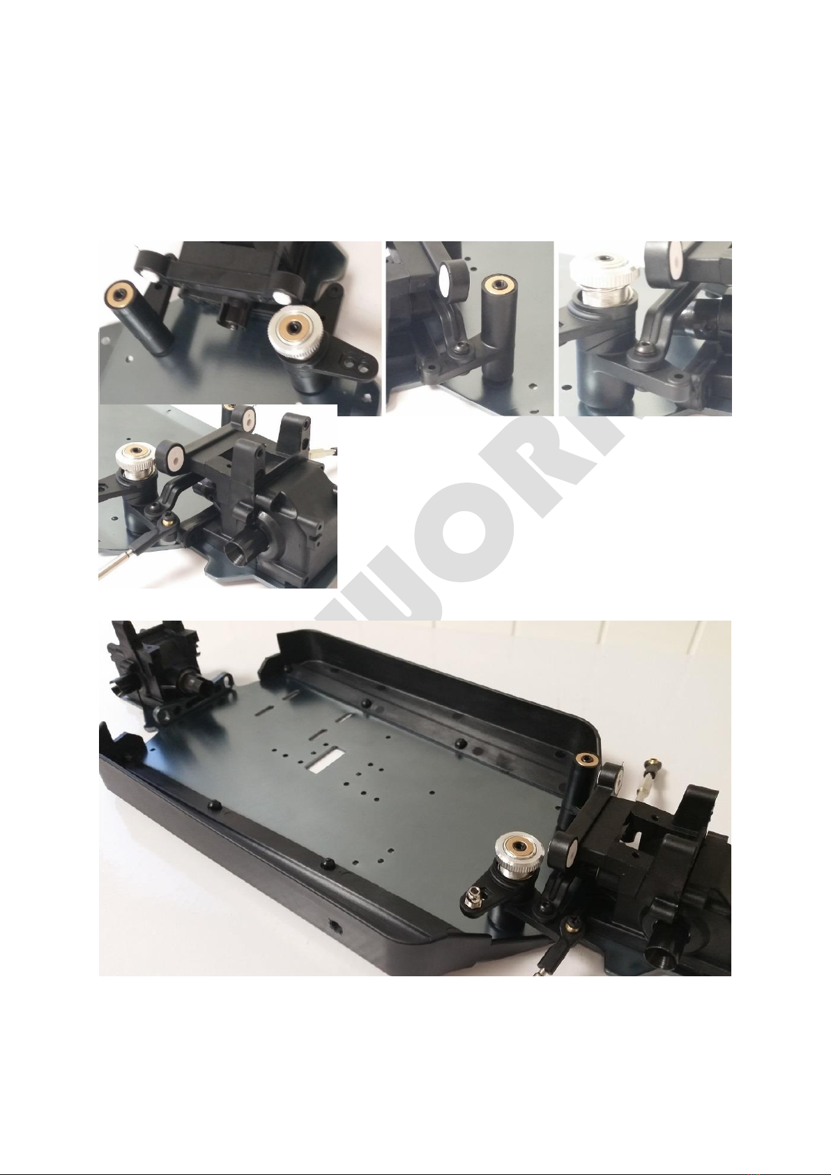
2.3: Place each of the cylinders onto the metal posts mounted on the Chassis in 2.1, the large two-
armed one should be on the left side and the narrow one on the right when the car is facing you, as
shown in pictures. Now fasten the remaining plastic part to the closest hole on each of the servo
posts arms, using the Hex-key half threaded Mech Screws. Make sure the screws are not too tight,
and that the Steering Saver Assembly rotates freely. Using one of the remaining Mech Screws, fasten
the metal Shock Ball to the arm as shown in picture.
2.4: Open bag 13 and fasten the Steering Links to the
Steering Assembly arms as shown in picture, using the
remaining two screws from bag 2, used in the previous steps.
2.5: Open bag 24 and fasten the Side Guards to the Chassis
using the screws included. Notice that the end of the Side
Guards that have a longer narrow piece is the front, while
the shorter curved part with the step is the back. Each part is
mounted using 4 self-tapping 3*8 screws, as shown in
pictures.
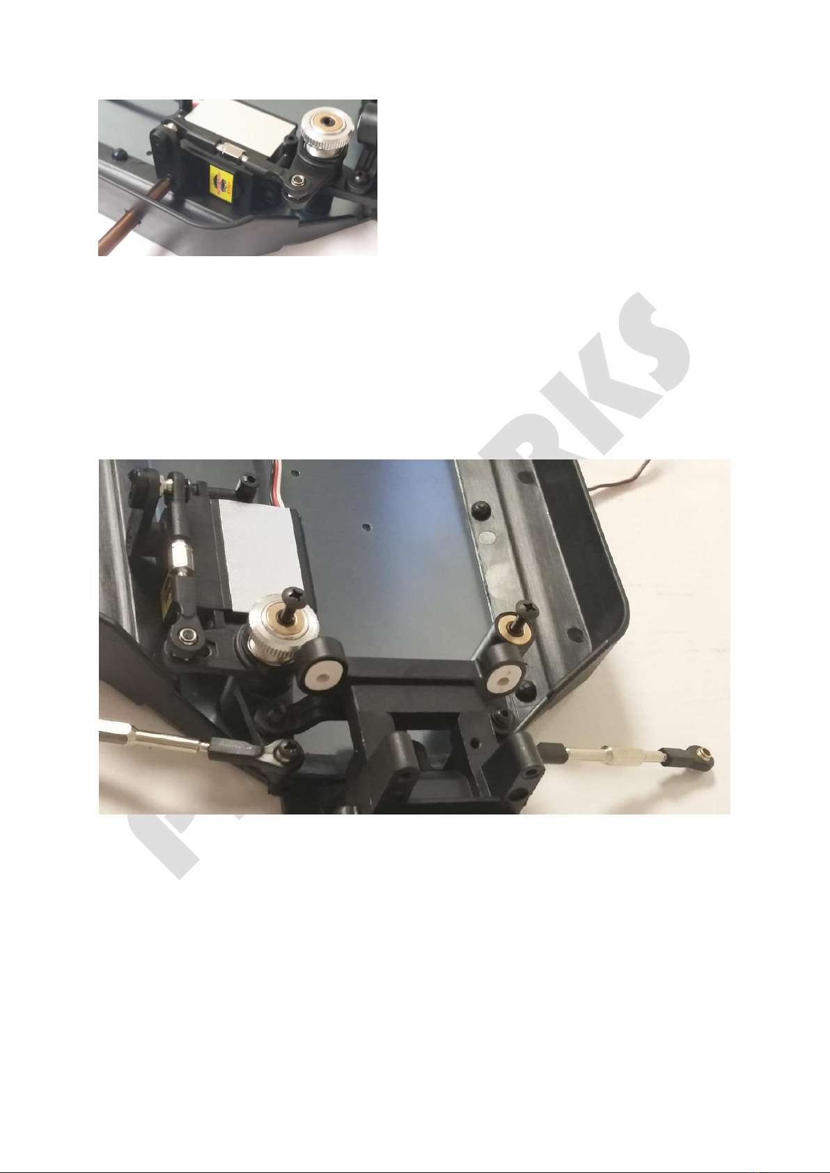
2.6: Open bag 20 containing the Servo, and start by
fixing the Servo Mounts to the Servo itself using the
short cap-head Mech Screws, as shown in picture.
Notice how parts are facing in relation to each other.
2.7: Fasten the Servo to the Chassis just behind the
Steering Saver. There are 4 holes, 2 for register pins
and 2 for screws. For this, use the Countersunk Self-
tapping Screws 3*10 from bag 9, the one the Chassis
was in. Then push the open end of the Servo Arm onto the shockball on the Steering Saver, and
finally fasten to the servo with the small Mech Screw remaining, as shown in picture.
If you are having difficulty mounting the servo properly, consider removing the sideguard for easier
access to the screws of the servo mount. When doing this, you will need to leave the screws securing
the servo to the chassis slightly lose so there is room for the sideguard to fit under the edge of the
servo.
Finally, screw the two remaining Cap Head Mech Screws lightly onto the top of the Steering Saver
Posts for later, as shown in picture.

3.0: Center Diff. and Braces
Youtube guide for this stage: https://youtu.be/OGpkpzO_GPk
Requires following bags:
10:
60032 Front Brace
60033 Rear Brace
60075 Column Head Mech Screw 3*30
60078 Cap Head Self-tapping Screw 3*10
61015 Rear Brace Mount
85793 Nylon Nuts M3
11:
60031 Front Universal Drive Joint
60063 Center Front Dogbone
60064 Center Rear Dogbone
60096 Rear Dogbone
12:
60048 Center Diff. Mount
60054 Center Diff. Top Plate
60079 Cap Head Self-tapping Screw 3*12
61016 Antenna Mount
14:
61004 Battery Cover
61006 Battery Case
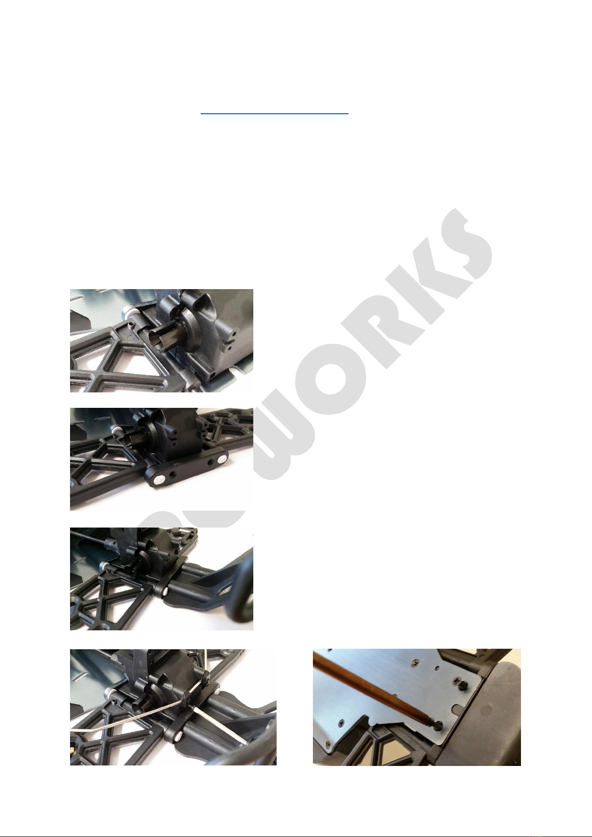
3.1: Open bag 10 and mount both Braces to the
Chassis using Self-tapping Screw 3*10 from bag 9.
Close to the middle of the Chassis you will see a
rectangular hole with 3 holes each side, and then two
holes in a row beyond those. These are the mounting
points for the Braces. The Brace with the pivoting
piece on top is the Rear Brace, the other one is the
Front Brace. Mount as shown in picture.
3.2: Retrieve from bag 11 the Center Front Dogbone and Center Rear Dogbone; these are the two
Dogbones of unique length –the longest and the shortest one, where the other 4 Dogbones are in
identical pairs. Have the remaining Dogbones stay in its bag for now! Also open bag 12, and get the
Center Differential you set aside from bag 7 in step 1.1.

3.3: The Center Diff. holders each have a slot for the
Ball Bearing on the Center Diff. to fit into. Mount
them, and then fasten the top plate onto the holders
using the Self-tapping Screws 3*12. Note that on one
side the Antenna Mount should be fastened, notice
the relation of parts in the picture. Use the Spacers
included if needed.
3.4: When placing the Center Diff. Assembly onto the Chassis, you must at the same time position the
Center Dogbones. The large gear on the Diff should face to the rear of the model, and the short
Dogbone goes towards the Rear, while the long Dogbone goes towards the Front. Make sure they
slot into the Drive Cups on both ends and then place the Center Diff. Asembly into the center of the
model, one holder on each side of the rectangular hole in the middle, and making sure register pins
are in their holes. Fasten using 4 Self-tapping Screw 3*10 from bag 9. Notice how all parts are
mounted in the picture, and see video for live construction.
3.5: Open bag 14 and mount the Battery Case behind the Servo using the remaining two Self-tapping
Screws 3*10 from bag 9.

4.0: Front Suspension Assembly
Youtube guide for this stage: https://youtu.be/atJNexfHyCs
Requires following bags:
5:
60004 Front Upper Susp. Arm
60005 Front Lower Susp. Arm
60043 E-Clips Ø2.5
60068 Front Hub Carrier Hinge Pins 3*21
60071 Front Upper Susp. Arm Hinge Pin 3*48
60072 Front Lower Susp Arm Hinge Pin 3.5*66
6:
60007 Front Shock Tower
60008 Rear Shock Tower
60009 Front Top Plate
60078 Cap Head Self-tapping Screw 3*10
60082 Cap Head Self-tapping Screw 3*18
61003 Radio Tray
62017 Body Post Mount (F)
62018 Body Post Mount (R)
85793 Nylon Nuts M3
11:
60031 Front Universal Drive Joint
16:
60027 Front Sway Bar+Link
60028 Rear Sway Bar+Link
60112 Column Head Mech Screw 3*16
18:
60078 Cap Head Self-tapping Screw 3*10
60081 Cap Head Self-tapping Screw 3*16
60084 Countersunk Self-tapping Screw 3*40
60123 Cap Head Self-tapping Screw 3*42
62049 Rear Bumper
62052 Front Bumber/Connect Plate
4.1: Open bag 5 and find the Upper Suspension Arms -60004- and the small bag with Hinge Pins. Take
the medium-length hinge pins and insert them into the white bushings on the Upper Susp. Holder on
the front of the model. Now find all the small black plastic clips from the bag in step 1.0 and place 3
on each of the pins, followed by the Upper Susp. Arms, and then another 3 plastic clips on each.

Notice how parts are placed in the picture. Fit the short hinge pins onto the ends of the Susp. Arms
and attach the e-clips; these will be used later.
4.2: Open bag 6 and find the Front Shock Tower -60007-, which is most distinct from the Rear Shock
Tower by its Body Post Mounts being smaller. Place the long white bushings from the same bag as
the plastic clips in the corresponding holes of the Shock Tower, making sure holes are pointing down,
and then mount it on the front Gear Box as shown, making sure the Hinge Pins of the Upper Susp.
Arm register in the holes of the white bushings.
4.3: Take the Front Top Plate -60009- from bag 6, remove the screws lightly fastened to the Steering
Saver posts and Front Brace, and then fasten the Front Top Plate to the Assembly with those same
screws, facing as shown in pictures, and use the Self-tapping Screws 3*10 in the small bag for the two
remaining holes. Then fix the Radio Tray -61003- on top of the Servo using the Self-tapping Screws
4.4: Place the long Hinge Pins remaning from bag 5 into the
holes of the Lower Susp. Holder, and then slide on the Front
Lower Susp. Arms -60005-. It is very important to notice how
this part is mounted, and note the small Grub Screw in the
part that should be facing up! Take the Front Lower Susp.
Arm Holder -60013- from bag 19 that was set aside in step
1.0, place two of the short white bushings in it with holes
pointing down, and mount it on the front as shown, with
hinge pins registering in the holes of the white bushing.
4.5: Open bag 18 and find the small bag containing screws.
Retrieve the 2 Countersunk Self-tapping Screws 3*40 -
60084- from the bag and use them to fix the Susp. Arm
Holder from step 4.4 to the Gear Box.

4.6: Fasten the Bumper support to the Shock Tower with 4
Self-tapping Screws 3*42 and the 4 plastic cylinders, as
shown in the picture. To mount the Front Bumper –this is
the one with the extra metal plate on it-, slide it under the
Susp. Arm Holder just mounted and fix from bellow with the
Self-tapping Screws 3*16 from bag 9. Some force may be
needed to push the part properly into place.
4.7: Open bag 16, and pick the Front Sway Bar –this is the shorter of the two, without the additional
bend on the ends. First attach it to the Lower Susp. Arms with Mech Screws 3*16 and in the correct
holes as shown, and then fix it to the font of the Gear Box with the small plastic Fasteners and
Screws. Finally, fix the Bumper Support to the Front Bumper with Self-tapping Screws 3*10 from bag
18.
5.0: Rear Suspension Assembly
Youtube guide for this stage: https://youtu.be/9OLnkHbNWD4
Requires following bags:
4:
60006 Rear Lower Susp. Arm
60034 Rear Upper Susp. Arm
60043 E-Clips Ø2.5
60067 Rear Hub Carrier Hinge Pins 3*19.7
60072R Rear Lower Susp. Arm Hinge Pin 3.5*64
All remaining parts from bags 6, 15, 16, 18 opened in previous steps.
5.1: Start by placing the short white plastic bushings in the
Rear Lower Susp. Holder, ensuring holes face down as
previously when placing these. Then push the long Hinge
Pins -60072R- from bag 4 through the Rear Lower Susp.
Arm -60006- from the same bag, and insert one end into
the bushings just mounted. Notice facing of the part in
relation to other; take particular care that the grub screw
must face upwards!
5.2: Now place the Rear Lower Susp. Arm Holder -60019-
on the Rear Assembly. Notice it will register in a cutout on
the Chassis plate, as well as the Hinge Pins of the Susp.
Arms. For this, ensure holes of the long white bushings
are facing out to each side. Then fix the Rear Bumper -
62049- from bag 18 onto the model using Cap Head Self-
tapping Screw 3*42 -60123- from the same bag. Using the
remaining 2 Self-tapping Screws 3*16 from bag 9, securely
fix the Rear Assembly to the Chassis from bellow.
5.3: Now mount the Rear Sway Bar from bag 16 in the
same manner as from step 4.7, by using the Mech Screws
3*16 and the small plastic Fasteners and screws from the
same bag. For the fasteners, the screw goes in the lower
of the two holes.

5.4: Place the Rear Shock Tower -60008- on the Rear Assembly, making sure it faces correctly with
Body Post Mounts towards the center as shown. Then position the Bumper Support from bag 18 and
fix to the model using Cap Head Self-tapping Screw 3*16 -60081- from the same bag, securing the
Rear Shock Tower at the same time. Finally, fix the Bumper Support to the Rear Bumper using Cap
Head Self-tapping Screw 3*10 -60078-, also from bag 18.
5.5: Unscrew the M3 Nuts and washers from the screws that are attached loosely to the Rear that
has a flat side on it, as shown on pictures. Then Replace the washer and nut, and secure tightly. Place
the short hingepins from bag 4 through the shockball on the end of the Rear Upper Susp. Arms, and
secure with e-clips for later.

6.0: Front Wheel Steering
Youtube guide for this stage: https://youtu.be/LCdSTITUWRw
Requires following bags:
8:
60017 Front Wheel Hub Carrier
60018 Steering Hub Carrier
60042 Steering Shaft Bush Ø5.8
61022 Ball Head Mech Screw 3*11
85711 Wheel Hex + Nuts
85763 Bearings 16*8*5
60031 Front Universal Drive Joint from bag 11 opened in step 3.2.
6.1: From bag 8, start by pushing a Ball Bearing 16*8*5 -85763- into each side of the Steering Hub -
60018-. Some force may be required, but ensure they are
flat and level in relation to the Steering Hub first, so that no
parts are damaged. From bag 11, push the front Universal
Drive Joint -85763- through the Bearings and rotate parts to
ensure a secure fit.
6.2: Now place the Wheel Hex -85711- on the end of the
Drive Joint, line up the register holes properly and then push
through the steel pin to secure both parts. This may require
considerable force, but again ensure holes are lined up
properly and all parts are level in relation to each other. Be
careful to not damage any parts. Rotate parts to ensure a
nice fit, and use washers if needed.
6.3: Place a Steering Shaft Bush Ø5.8 -60042- into the suitably sized holes on the Hub Carrier -60018-
from the inside, as pictured. Then place the Dogbone of the Steering Hub Assembly through the large
hole in the Hub Carrier, line up the holes with the Bushings and secure using Ball Head Mech Screw
3*11 -61022-. Take careful notice of relation of parts to each other in the pictures, both sides are
mirrored versions of each other.

6.4: To fix the Steering Assembly to the model, first remove the hinge pin on the Front Lower Susp.
Arm by removing the screws securing it, and pushing it out. Put the Steering Assembly into place,
making sure the end of the dogbone register in the drive cup of the Front Differential, and replace
the hinge pin as shown. Then remove the e-clip from one side of the hinge pin in the Front Upper
Susp. Arm, remove the pin to lover the arm in place, and then replace the pin and secure with e-clip.
Finally, secure the Steering Links to the Steering Hub using Ball Head Mech Screw 3*11 from bag 8.
Move the Front Suspension Assembly with your hands and turn the Wheel Hex to ensure a correct fit
and freedom of motion for the parts in this assembly.

7.0: Rear Hub Carrier
Youtube guide for this stage: https://youtu.be/It2UNu_tbUM
Requires following bags:
17:
60012 Rear Hub Carrier
60093 Wheel Axle
85711 Wheel Hex + Nuts
85763 Bearings
85834 Set Screws 5*4
60096 Rear Dogbones from bag 11 opened in step 3.2.
7.1: As in the previous assembly, start by pushing into place the Ball
Bearings 16*8*5 -85763- on each side of the parts, making sure they
are level in relation to the part before force is applied. Push the Wheel
Axle -60093- though the bearings and rotate to ensure parts are fitted
correctly.
7.2: Place the Wheel Hex -85711- on the end of the Wheel Axle, line up
holes of both parts and push the steel pin through. As with the
previous assembly in step 6.2 some force may be required, but take
care to not damage any parts in the assembly. Rotate parts to ensure a
correct secure fit and low friction movement, use washers if needed.
7.3: To secure the part to the model, first remove the Hinge Pin from
the Rear Lower Susp. Arm, similar to in step 6.4, by removing the
locking screws and pushing the pin out. Place the Hub Carrier Assembly
correctly, and then replace the pin and fasten screw, as shown in
picture. Now position the Rear Dogbone -60096-, making sure it
registers in Drive Cups of both the Rear Differential and the Rear Hub
Carrier. Finally, remove the Hinge Pin from the Rear Upper Susp. Arm by removing an e-clip, lower
the arm into place and then replace the Hinge Pin and e-clip.

8.0: Shock Absorbers
Youtube guide for this stage: https://youtu.be/nZcVRNLHfdc
Requires following bags:
1:
60003 Shock Absorber
60040 Shock Absorber Link Ball Ø5.8
60041 Shock Balls Ø5.8
60081 Cap Head Self-tapping Screw 3*16
18044 Round Head Screw 3*25
85793 Nylon Nuts M3
8.1: First, secure the Shock Absorbers -60003- to the Lower Susp. Arms using
Cap Head Self-tapping Screws 3*16 -60081- though the brass shock ball. The
screw should go in the center hole for now, this is true for both front and
rear.
8.2: Push the Round Head Screws 3*25 18044 though the suitable hole in the Shock Tower, mount
the Steel Shock Ball on the Shock Absorber on the screw, and place a washer and M3 nut before
securing. For the front the Shock Absorber should be fastened in the uppermost of the 6 holes where
the Body Post Mount is, while for the rear it should be mounted in the center lower hole where the
Body Post Mount is, as shown in pictures.

9.0: Electronics
Youtube guide for this stage: https://youtu.be/F6IEQ6Atb7M
Requires following bags:
21:
61007 Receiver Case
61008 Motor Secure Plate
61009 Motor Mount
61010 Motor Heat Guard
61012 Cooling Fan & Guard
61013 Steel Pinion Gear (14T)
61024 Countersunk Mech Screw 3*8
61028 Brushless Motor 3000KV
13308 Brushless ESC (80A)
Receiver from bag 23
9.1: Attach the Motor Secure Plate -61008- to the motor using Countersunk Mech Screws 3*8, and
the Pinion Gear -61013- with the grub screw. For the Pinion Gear, make sure it is fastened securely
against the flat side of the motors drive shaft. Slide the Heat Guard onto the Motor –missing from
bag in initial production! Included separately- .
9.2: Attach the Motor Mount to the Chassis using the Roundhead screws, and then fasten the Motor
Assembly, so that the back of the Motor is cradled by the Motor Mount.
9.3: If you wish, secure the Receiver Case -61007- to the Chassis using Countersunk Self-tapping
Screws 3*8 in what should be the only remaining available position on the Chassis. Some prefer not
to use this and instead attach the ESC directly to the steel chassis because it affords them more space
and freer placement of electronics.
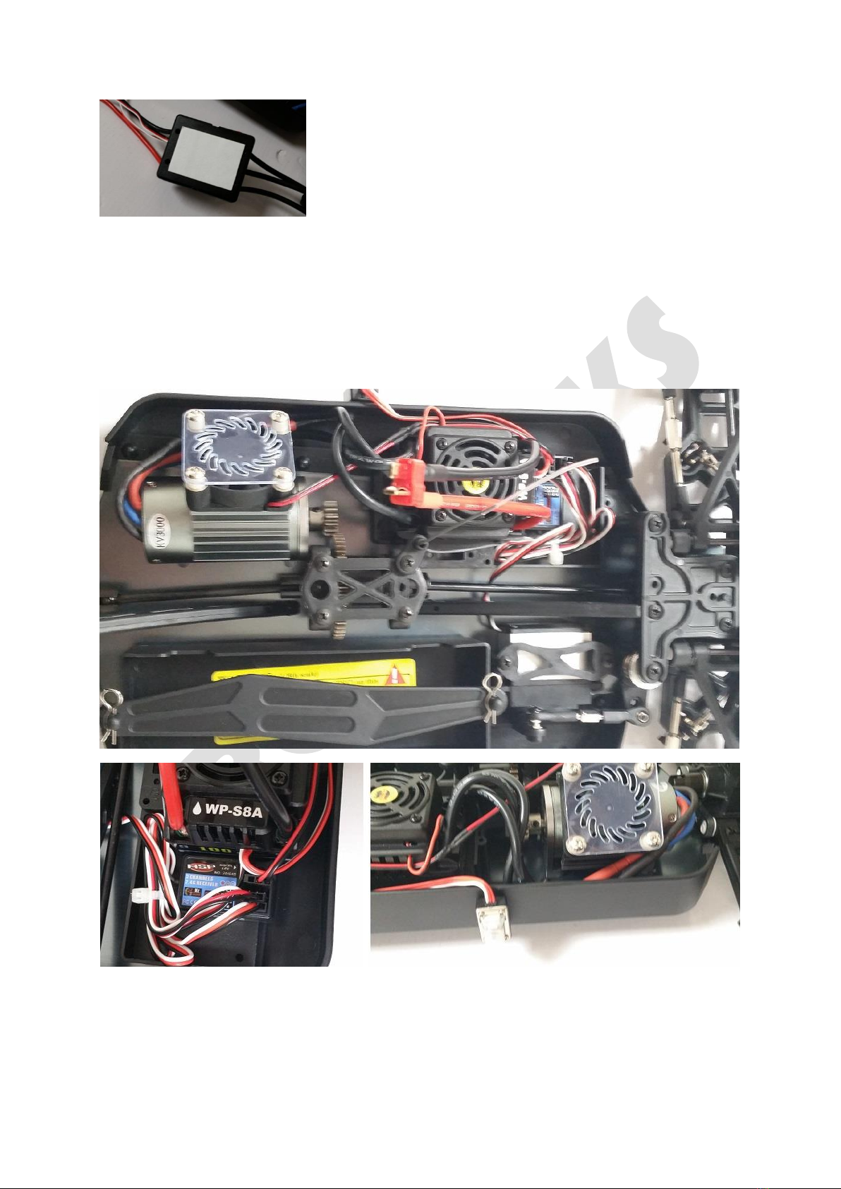
9.4: Using the two-sided adhesive patches, attach the ESC and it’s
On/Off switch to the Receiver Case. From bag 23, get the receiver
and attach it on the Receiver Case next to the ESC as shown. Then
Connect the wires from the Motor to the ESC, ensuring each wire
goes to its corresponding color! Attach the Wires from the Servo
and ESC to the receiver as shown, and properly secure wires with
zip ties provided. Thread the Antenna from the receiver through the Antenna Mount. For this model
with the 2,4GHz receiver, the signal range will be good enough for most even without using the
antenna tube. Not using the antenna tube will also mean the car body does not require a hole drilled
in it, which results in a sleeker look. If you want the additional range, feel free to use the antenna
tube, and drill a hole in the chassis where required; take care to measure accurately where the
antenna will go, so you don’t need to make several redundant holes! Making a hole in the body
without specialist tools can be easily achieved by puncturing it with a sharp knife, then rotating the
knife to create a circular hole of a suitable size.
9.5: Connect the Servo to the receiver in Ch1 and the ESC in Ch2, and the fan cable in the VCC slot.

10.0: Final Preparations
Requires following bags:
22:
7,4v 3500mAh LiPo Battery
23:
Transmitter
25:
7,4v LiPo Balance Charger
26:
62054 Wheels Complete
Chassis
10.1: From bag 26, open the smaller bag inside containing wheels. On the inside of the rim you will
see a hexagonal cutout with a circular hole, that fits perfectly on the Wheel Hex on your model. Slot
the wheels into place so that they register on the Wheel Hex –notice pattern on wheels indicates
direction; arrow-like shape should face to the front, then fasten with Hex Nuts. Take care to not
make the nuts too tight, as this may damage the plastic rims and cause them to break during high-
stress driving. The wheels should be secure with minimum wobble, but large amounts of force should
not be applied while fastening.
10.2: The battery in bag 22 is partially charged so initial adjustments of the car is possible right away,
but we advise charging the battery fully using the charger from bag 25 first. Notice that the charger
will indicate cell 1 and 2 connected on the battery included, and both cells will flash green when the
battery if fully charged. Do NOT charge the battery using equipment not specifically for charging of
LiPo batteries, as this could pose a serious hazard. If the battery shows any sign of physical damage,
consult an experienced user before considering using the battery. Read online about safe usage and
storage of LiPo batteries.
Table of contents
Popular Motorized Toy Car manuals by other brands


Disney
Disney PIXAR Cars 2 FINN MCMISSILE manual

Agora Models
Agora Models 1965 SHELBY COBRA 427 S/C Build instructions

Viessmann
Viessmann 8010 Operation manual

MTHTrains
MTHTrains Premier F40PH Diesel Engine Operator's manual

Jamara
Jamara Slighter CR1 Instruction

Duratrax
Duratrax Raze Assembly and operation manual


