Proyecson PAA29+ User manual

PAA29+ v1.4 (07/2011)
INSTALLATION MANUAL
PAA29+

INSTALLATION MANUAL: PAA29+ V 1.4 (07/2011) 2
Imprint
All ri hts reserved
© Copyri ht by Proyecson S.A.
Ronda Gu lielmo Marconi 4.
Parque Tecnoló ico.
46980 Paterna (Valencia)
Spain
Printed in Spain, issue September
2009
This operatin manual even in
extracts may only be reprinted or
otherwise copied with special,
written permission from Proyecson
S.A.
Editor responsible for the contents:
Proyecson S.A.
Editin and layout:
Proyecson S.A.
Ronda Gu lielmo Marconi 4
Parque Tecnoló ico
46980 Paterna (Valencia)
Spain

INSTALLATION MANUAL: PAA29+ V 1.4 (07/2011) 3
TABLE OF CONTENTS
1. SAFETY ..............................................................................................5
1.1
GENERAL 5
1.2
INSTALLATION 5
1.3
PROPER USE 6
2. INTRODUCTION .................................................................................7
3. FEATURES ..........................................................................................8
4. FRONTAL PANEL ..............................................................................10
5. REAR PANEL.....................................................................................11
6. CONNECTION PROCEDURE ...............................................................12
6.1
CONNECTION TO A DOLBY SERVER 12
6.2
CONNECTION TO A DOREMI SERVER OVER ETHERNET 15
6.3
CONNECTION TO A DOREMI SERVER USING THE SERIAL PORT 17
6.4 CONNECTION TO A DOREMI SERVER USING THE GPIO PORT 19
7. CONFIGURATION OF THE PAA29+ ETHERNET PORT........................20
7.1 OVER A TCP/IP CONNEXION 20
7.1.1 CONFIGURE THE ETHERNET FOR A DOREMI SERVER 23
7.2. THROUGH A RS232 CONNECTION 25
8. SER ERS CONFIGURATION ..............................................................28
8.1. SERVER SELECTION IN THE PAA29+ 28
8.2. DOLBY SERVER CONFIGURATION 28
8.3 DOREMI SERVER SET-UP 31
8.3.1 ADD THE PAA29+ TO THE SERVER 31
8.3.2 SETUP THE OUTPUT CUES (NON-LIBRARY METHOD) 33
8.3.3 SETUP THE OUTPUT CUES USING PAA29+ XML LIBRARY 36
8.3.4 SETUP THE INPUT CUES USING PAA29+ XML LIBRARY 40
9. OUTPUTS / INPUTS OF THE PAA29+................................................43
9.1. OUTPUT 1 CONNECTOR: 43
9.2 OUTPUT 2 CONNECTOR: 44
9.3 OUTPUT 3 CONNECTOR: 45
9.4 INPUT CONNECTOR: 46

INSTALLATION MANUAL: PAA29+ V 1.4 (07/2011) 4
9.5 EXAMPLES OF INPUT CONNECTION: 47
9.5.1 INPUT WITH A NEGATIVE COMMON: 47
9.5.2
INPUT WITH A POSITIVE COMMON: 48
10. NOTES............................................................................................49
10.1 FIRMWARE VERSIONS 49
11. ELECTRICAL PROPERTIES ..............................................................49
12. DIMENSIONS .................................................................................50
APPENDIX A: SERIAL COMMANDS FOR DOLBY.....................................51
APPENDIX B: COMMANDS FOR DOREMI SER ERS................................53

INSTALLATION MANUAL: PAA29+ V 1.4 (07/2011) 5
1. SAFETY
1.1 GENERAL
IMPORTANT: READ THIS MANUAL ALONG WITH THE MANUAL OF
EACH PART OF THE POWER SUPPLY.
•Never modify or handle the mechanical or electrical safety devices
installed in the power supply.
•Do not chan e or modify in any way the ori inal desi n of the power
supply.
•If the power supply does not work properly, stop at once and notify the
installer service.
•In case of an eventual repair, leave it in the hands of the distributor who
installed it.
•Always use ori inal spare parts and accessories, which must be installed
by an authorized installer.
1.2 INSTALLATION
•Do not handle the electrical system of the power supply. It must be
installed by an authorized technician.
•Installation must be done in conformity with the operatin manual and
the local security norms. The customer and the installer take
responsibility for the non-compliance of the norms.
•Before startin , verify the line connections, as well as the earth
connection and/or differential and ma neto-thermic switches. There
could be an electrical dischar e if you don’t follow the above-mentioned
procedure.

INSTALLATION MANUAL: PAA29+ V 1.4 (07/2011) 6
1.3 PROPER USE
•Do not use this power supply if you have not previously received the
necessary instructions of safety, use and cleanin by an expert user.
•Read and understand the operatin manual of this power supply before
usin .
•Keep your hands away while the power supply is in operation.
•Don’t leave the power supply durin operation.
•Do not wear any loose clothes or jewelry which could et cau ht in the
movable parts.
•Always disconnect the power supply before cleanin or any kind of
maintenance or repair. Pull out the plu from socket (do not pull from
cable). Keep cable away so as not to step on it, which could be
dan erous.
•Make sure that all safety metal plates and stickers on power supply are
easily readable. If not ask your distributor for more and attach them.
•For maintenance, cleanin works,… the system must be disconnected
from the main supply. Do not operate the power supply without havin
received the proper safety, use and cleanin instructions from an expert
user.

INSTALLATION MANUAL: PAA29+ V 1.4 (07/2011) 7
2. INTRODUCTION
The Proyecson PAA29+ Automation adapter makes it easy to interface di ital
cinema playback equipment with existin cinema control systems, enablin fully
automated presentations.
Input and output connections enable di ital cinema equipment to control
existin li htin , automation, and other old systems. The unit converts network
or serial control from the di ital cinema playback system in relay closures. The
unit can be connected in parallel with existin film automation systems makin
it easy to switch between film and di ital shows, and even to run seamless
presentations mixin both film and di ital content.
Advanced features include 12 confi urable momentary / latchin outputs and 8
inputs that can be used for tri er individual cues. These relay closures can
drive 16 A 250 Vac / 16A 30Vdc in normally open and closed dry contacts.
Front-panel indicators are provided for all inputs and outputs, ensurin that
system status is clearly visible at all times.
The unit is easy to install and 19” rack-mounted. Rear panel connectors are
provided to allow an easy wirin .
Valid for any other application not related with Di ital Cinema.

INSTALLATION MANUAL: PAA29+ V 1.4 (07/2011) 8
3. FEATURES
PAA29+ Front Panel
Power Button
With LED indicator.
LED Indicator
General purpose input, relay
output status, +24 V and + 5
V.
Test Buttons
Buttons for test and manually
activation purposes for each
input/output.
PAA29+ Rear Panel
Connections
General Purpose Inputs
Ei ht opto-isolated low-
volta e inputs, screw
terminals, 24V lo ics.
General Purpose Outputs
Twelve hi h current
latcheable relay outputs,
screw terminals, normally
closed and normally open
contacts 16A VDC max.
Relays are replaceable.
24v / 1A output
Usable for input and output
auxiliary circuits.
Serial Ports
9-PIN female D-connector.
Network Connection
RJ-45 female connector;
10Base-T.

INSTALLATION MANUAL: PAA29+ V 1.4 (07/2011) 9
Construction
Warranty
Industrial chassis, screw closure,
connectors in the back panel, 1
unit 19” rack-mountin .
Three years limited, parts and labor;
see disclaimer. Specifications subject to
chan e without notice.
Power Requeriments
Disclaimer of Warranties
100-240 VAC, 50-60 Hz, 50w
from a centrally switched power
source.
Dimensions and Weight
483 x 183 x 44 mm.
Environmental Conditions
Operatin : 0º to 40º (32º to
104ºF), 20 to 80% relative
humidity (non-condensin ).
Equipment manufactured by Proyecson
S.A. is warranted a ainst defects in
materials for a period of three years
from the date of purchase. There are
no other express or implied warranties
and no warranty of merchantability or
fitness for a particular purpose, or of
non-infrin ement of third-party ri hts
(includin , but not limited to, copyri ht
and patent ri hts).
INSTALLATION MANUAL: PAA+29 V 1.2
(05/2010)
10
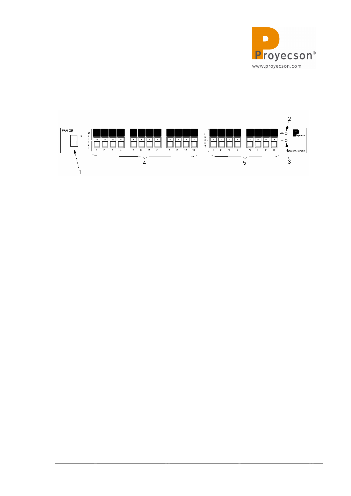
4. FRONTAL PANEL
Figure 4.A
1. Power button
2. 24vdc indicator
3. 5vdc indicator
4. Manual activation push button and output active status led’s.
•The led indicate that the output is active.
•Activate the outputs directly with the push bottoms without
usin the server. Outputs will only remain active while keepin
button pressed.
5. Manual activation push button and input active status led’s.
•The led indicate that input is active.
•With push buttons it is possible to force inputs manual
activation.
Table of contents
Other Proyecson Adapter manuals


