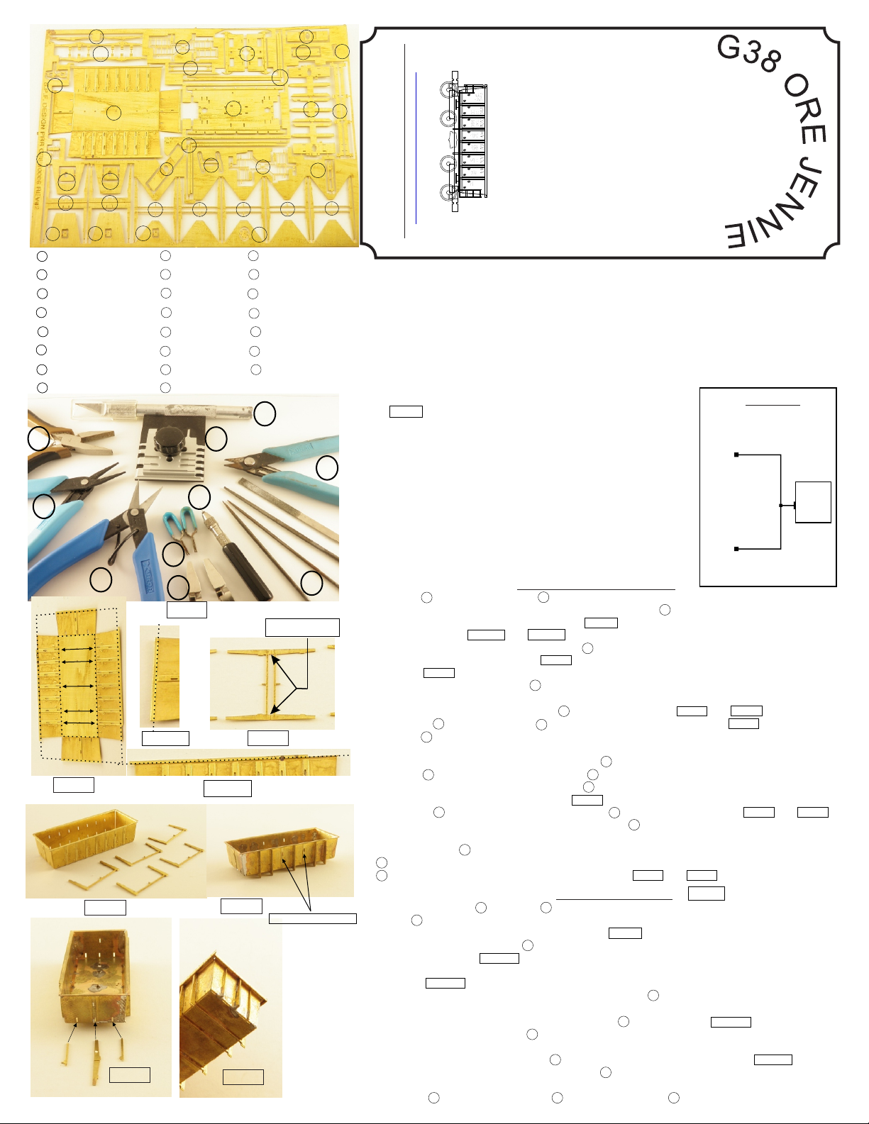
PRR S.P.F. DESIGN G38 ORE JENNIE User manual
c
F
.
.
D
P
E
.
S
S
I
G
R
N
R
P
Not intended for children under the age of 14
G38 Ore Jennie first built in 1960 in the
Sam Rea shops for the soul purpose of
hauling iron-ore. A thousanf of these
cars were built for the PRR in number
sequence 15000 - 15999, with a
capacity of 140,000 lbs and 1,048 cu.
ft. The G38 lasted well into the 1990’s
hauling ore for three different railroads,
the PRR, Conrail, And Penn Central all
of which can be represented with this
kit.
FIG.1
FIG.2
FIG.3FIG.3
FIG.4 FIG.5
( I have made a few changes in the directions for changes and additions see page 5 )
Thank you for your purchase from PRR S.P.F. Design. Begin by unpacking your kit and checking
its contents to the parts list below. Take a few minutes to read all the directions to familiarize
yourself with the parts and methods needed for assembly. The kit is designed to be glued or
soldered together. If you prefer to glue your kit I suggest using a thick CA for a better bond. If you
prefer to Solder the kit together I suggest 60/40 solder, Kester water
soluble flux. Flux is the key to getting solder to flow where you want it without de
soldering other items. The kit is also designed with locking tabs and bend lines to facilitate
assembly . Follow all directions. Should you have any problems, please contact me at
a 700 degree iron, and
quickly
Leave these two open
Here in FIG.1 are some suggested tools and items for
assembling this kit.
A - Flat nose non serrated plier found at any local hardware store
B - Xuron tweezer point pliers
C - Xuron photo etch shears
D/E - Various clamps
F- Pin vice with a #80 drill, # , and 00-90 tap
G - Assortment of needle files
H - Xuron micro sheers
I - Small shop photo etch bending tool www.thesmallshop.com
J - Exacto Knife
A
B
C
D
E
F
G
H
I
J
A
A - Main Body B - Main Ribs C - Center Rib Ends
D - Left And Right End Ribs E - Floor F - Floor Ends
G - Under Floor Bracing H - Center Bracing I - Bolster
J - Bolster Covers K - Air Tank Brackets L - Brake Eccentric
M - Center Ribs N - Brake Tower O - Brake Platform
P - Brake Gear Housing Q - Brake Wheel R - Brake Rod
S - Ladders & Stirrups T - Ladders & Stirrups U - Top Cord
V - Grab Iron Bending Jig W - Coupler Spacers
1.) Remove A -Main Body and five B -Main Ribs.
2.) With bend line up, bend the four very outer edges of the A -Main Body towards you 90
degrees. The outer dashed line shown in FIG.2 indicates the four places for these bends.
Refer to close-up FIG.2A and FIG.2B note the bend line is just under the outer etched edge.
3.) With smooth side up, now bend the four A -Main body sides up to form the Main body.
Refer to the inner dashed line in FIG.2 for where to bend.
Refer to FIG.4 to see finished assembly.
4.)
Floor Assembly FIG. 8
10.) Start by removing E -Floor and F -Floor Ends
11.) With , bend both sides of along etched lines up
until a 90 degree angle is achieved. Refer to FIG. 9.
12.) Orient the bend lines up on F -Floor Ends bend the edge with the two small triangles up to
90 degree.
13.)Take notice to the difference in the number of slots in bent in the previous
step. One end has three slots near the initial bend and the other will have only two one in
each corner. Now take notice to the slots in the reference FIG.9b the two horizontal
slots in the center are for the egin with the bends facing up on all
three components. The two close-together slots on the one side of the must be
attached on the same side as the slots, again refer to FIG.9b. Next,
slide each Floor Ends into either side of the making sure the ends are flush and
that all slots on each piece line up.
15.) Remove G -Under Floor Bracing, H -Center Bracing and I -Bolster
With the bend line up, fold the B -Main Ribs along the center bend line away from you until it
doubles itself.
Repeat this process for each of the B -Main Ribs. Refer to FIG.3 and FIG.4
5.) Fasten the B -Main Ribs to the A -Main Body to locations indicated in FIG.5. Take notice
how the A -Main Body tab slots are staggered; the main ribs must be oriented correctly to
match slots.
You may have to file or trim the top edges of B -Main Ribs to achieve proper fitment.
6.) Remove C -Center Rib Ends and the four D -Left And Right Rib Ends.
7.) With the bend line oriented up, fold each C -Center Rib Ends along the center bend line
away from you until it doubles. refer to FIG.6
8.) Attach one C -Center Rib Ends to each end of A -Main Body as shown in FIG.6 and FIG.7
note: you may have to file or trim the top edges of C -Center Rib Ends to achieve proper
fitment.
9.) Next, fasten the D -Left And Right Rib Ends to the slots adjacent to either side of the
C -Center Rib Ends Again, it may be necessary to file or trim the top edges of the
C -Center Rib Ends to achieve a good fit. Refer to FIG.6 and FIG.7
E -Floor bend lines oriented up E -Floor
refer to FIG.9a .
13.) Finish the F -Floor Ends by bending the two small triangles down perpendicular to the floor
Refer to FIG.9a .
F -Floor Ends
E -Floor
K -Air Tank Brackets. B
Floor End
K -Air Tank Brackets
E -Floor
FIG.2a
FIG.2b
www.prrspfdesign.weebly.com
BBBBB
JL
MM
N
PPPQ
T
W W
Main Body Assembly
FIG.6 FIG.7
A
C
D
E
F
GH
I
J
K
O
R
S
U
U
V
Parts list
1- G38 Etching
2- decal sheet (optional)
3- air tank
4- triple valve Small
parts
5- air cylinder bag
6- .010 wire
7- printed directions
(optional)
Bend lines
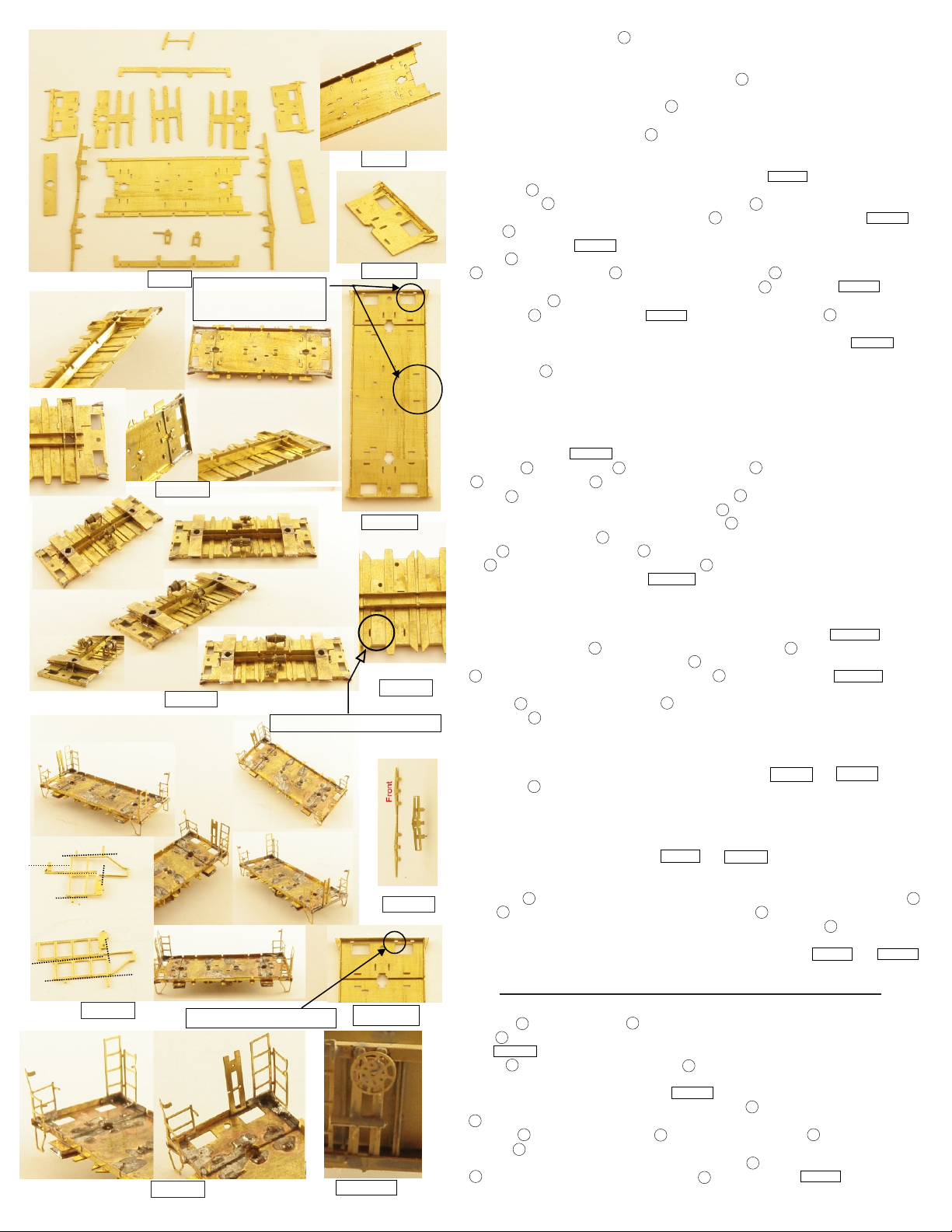
FIG.8
FIG.9
FIG.10
FIG.11
FIG.12
FIG.13
FIG.14
FIG.15
FIG.9a
Be sure these two slot line up
16.) Locate the center piece of G -Floor Bracing and with the bend lines orientated
up bend the two small tabs on either side up to 90 degrees
17.) Orient the bend lines on the outer two pieces of G -Floor Bracing up and
bend the small tabs up at a 90 degree angle.
18.) Position the previously assembled with the bent edges down. You will
be looking at what is to become the underside of the ore car.
19.) Now align the three sections of on top of the floor making sure
all slots have clearance and that all the small tabs are located in
their proper slots of the floor. Also, the small notch in the center section of floor
bracing, must line up with the slot in the floor. refer to FIG.11.
20.) Insert the into the corresponding eight horizontal slots in the
center of the . Do so by going through the . Once
through bend the tabs over on the inside of to secure. Refer to FIG.10.
21.) Bend I -Bolsters into a rectangle keeping all bend lines to the inside of the
rectangle. refer to FIG.12 .
22.) Insert I -Bolsters into the corresponding four vertical slot at each end of
E -Floor Bracing through G -Floor Bracing locking into H -Center Bracing once
through and flush bend over all tabs on the inside of E -Floor.( see FIG.10 ).
23.) Remove both , and note the differences between the two.
24.) Orient the as shown in with the two slots for the
facing you. Inset the air tank bracket with the leg into the right slot.
Insert the other bracket (no leg & longer tab) into the left slot. refer to
26.) Remove the Triple Valve, Air Tank and the Air Cylinder from the parts bag. Install
them as shown in FIG.13.
27.) Remove N -Brake Tower, O -Brake Platform, three P -Brake Gear Housing’s,
Q -Brake Wheel, and R -Brake Rod.
28.) Insert R -Brake Rod long end first into the three P -Brake Gear Housings.
29.) with etch detail up and the single hole up on N -Brake Tower insert the assembly
from previous step 28.) into the single hole on N -Brake Tower.
30.) top this assembly with Q -brake Wheel.
31.) with N -Brake Tower oriented Q -Brake wheel up insert the two small legs
of O -Brake Platform into the two holes in N -Brake Tower making sure that the
offset is to the left as shown in
32.) With the platform now attached to the tower, bend each of the long platform legs
to form an angular support for the platform. Note that there are two etch lines for
each leg. One will form the 45˚ downward angle, and the other will form a short
tab parallel to the brake tower as a location for bonding. Refer to FIG.14b .
33.) Install the completed N -Brake Tower assembly onto the E -Floor
assembly in its proper slot in the Single F -Floor End with three slots. The
N -Brake Tower goes in the inner slot of this F -Floor End refer to FIG.14a .
Once secured trim bottom of tab flush with floor.
E -Floor
G -Floor Bracing
H -Center Bracing
E -Floor G -Floor Bracing
E -Floor
K -Air Tank Brackets
E -Floor FIG.13 K -Air Tank
Brackets
FIG.13
25.) Remove the J -Bolster Covers. With the etched pockets faced down, mount
the covers onto the bolster tabs and form the covers onto the bolsters.
Note: For glue users, after formed and fastened, check the fit of the truck
pin. You want it to be a very light press fit
FIG.14b
34.) remove S -Ladders & Stirrups and T -Ladders & Stirrups.
35.) Orient the S -Ladders & Stirrups with etch lines up and the stirrups facing you.
Begin by bending the two small ladder supports to the left down at 90 degrees at
their etch lines. Next, bend the top edge of the stirrup at the
etch line down at 90 degrees. Now bend entire the part along center etch line
(between ladders) to form a 90 degree angle. Refer to FIG.14 and FIG.15.
36.) Orient the T -Ladders & Stirrups with etch lines up and the stirrups facing you.
Begin by bending the two small ladder supports on either side down at 90
degrees at their etch lines. Next, bend the top edge of the stirrup at the
etch line down at 90 degrees, as well as the small tab at the top middle of the
ladder/stirrup. Now bend entire part along center etch line (between ladders) to
form a 90 degree angle. Refer to FIG.14 and FIG.15 .
37.) With the E - Floor assembly in hand Insert the tabs of each Ladders & Stirrups S
and T into their designated slots at each end of the E - Floor. Next, insert the
long lower ladder support in the small slots on either side of the E - Floor. Next,
attach the front of the stirrups to the front edge of the floor ends. Trim excess tab
flush with bottom the E - Floor to finish up assembly. Refer to FIG.14 and FIG.15
Main Body and Floor assembly and final detail
38.) remove M -Center Ribs and U -Top Cord
39.) with U -Top Cord oriented bend lines up bend both edges to 90 degrees
see FIG.16
40.) install U -Top Cord on the top edge of A -Main Body. Once attached
form the front edge with the two holes for the grab iron to the contour provided
and then trim off the excess. refer to FIG.17
41.) with a 00-90 tap, tap the two holes at each end of E -Floor for the couplers in the
F -Floor Ends.
42.) Join the E -Floor assembly to the A - Main Body making sure E -Floor is flush up
against A -Main Body.
note: you may have to trim the ladder supports on S -Ladders & Stirrups and
T -Ladders & Stirrups for a proper fit onto A -Main Body see FIG.18
43.) Attach the tops of the long ladders as well as the brake tower to the body.
FIG.9b
Be sure the upper two
slots line up with these
middle two slots
FIG.14a
FIG.14b
N - Brake Tower assembly
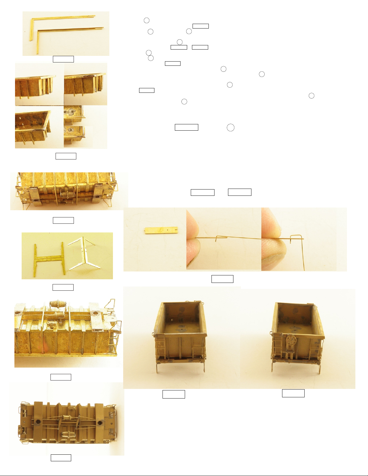
FIG.16
FIG.17
FIG.18
FIG.19
FIG.20
FIG.21
44.) Orient M -Center Ribs with etch lines up. Bend ribs away from you and back against themselves until
they are doubled up. Refer to FIG.19.
A -Main body E -Floor
and right of the center. Make certain the tabs on the center ribs are oriented correctly to match the
slots in the slots in the A -Main body. These are a tight fit, but be patient and work them down until they fit
into place. Refer to FIG.18 & FIG. 20. You may need to trim the top edges to achieve proper fit.
46.) remove L -Brake Eccentric and the provided .010 brass wire.
47.) position L -Brake Eccentric in the center on the bottom of the car with one rod to each side of the brake
cylinder. refer to FIG.21
48.) with a #80 drill bit drill, out the four holes in L -Brake Eccentric
49.) with provided .010 wire make four brake rods to attach to the L -Brake Eccentric.
bend a small 90 at one end of each rod to insert into the #80 holes you drilled out
attach the opposite end onto the underside of I - Bolster cover.
see FIG.21 .
50.) with a #80 drill , drill out the holes for the six grab irons, there are two at each end of F -Floor Ends
one at each top edge of A -Main Body
45.) With the and assemby together, install the center ribs into the two remaining slots
left
Here below in FIG.22 we have V - cut from the
etch.
Start off by bending a small 90 degree bend in the supplied wired with
appropriate tool. Insert this bend into the small hole ,with the long end
towards the supplied slot. Hold down on the bend , bend the long end
down at a 90 degree angle into the provided slot. Now cut the bent
Grab iron free and repeat the process for the six grab irons needed for
the kit. Once they are all bent attach them in the six location described
in step 49.) refer to FIG.23 and FIG.24
Grab Iron Bending Jig
FIG.22
FIG.23 FIG.24
This kit is designed for Micro-trains Trucks. For later Conrail and Penn Central, I would suggest
their Bettendorf trucks.
For G38's, I suggest their Andrews trucks. For the early version of the G38, Bowser makes the
correct trucks. You will just need to ream out the truck pin hole to accept a Micro-trains truck pin.
If you prefer to use BLMA, 70 ton friction bearing trucks, you will need to shim the bolsters for the
correct height ride height.
Use either 1015-1016 Micro-trains couplers; however, with a little bit of shimming you can use Z
scale couplers as well.
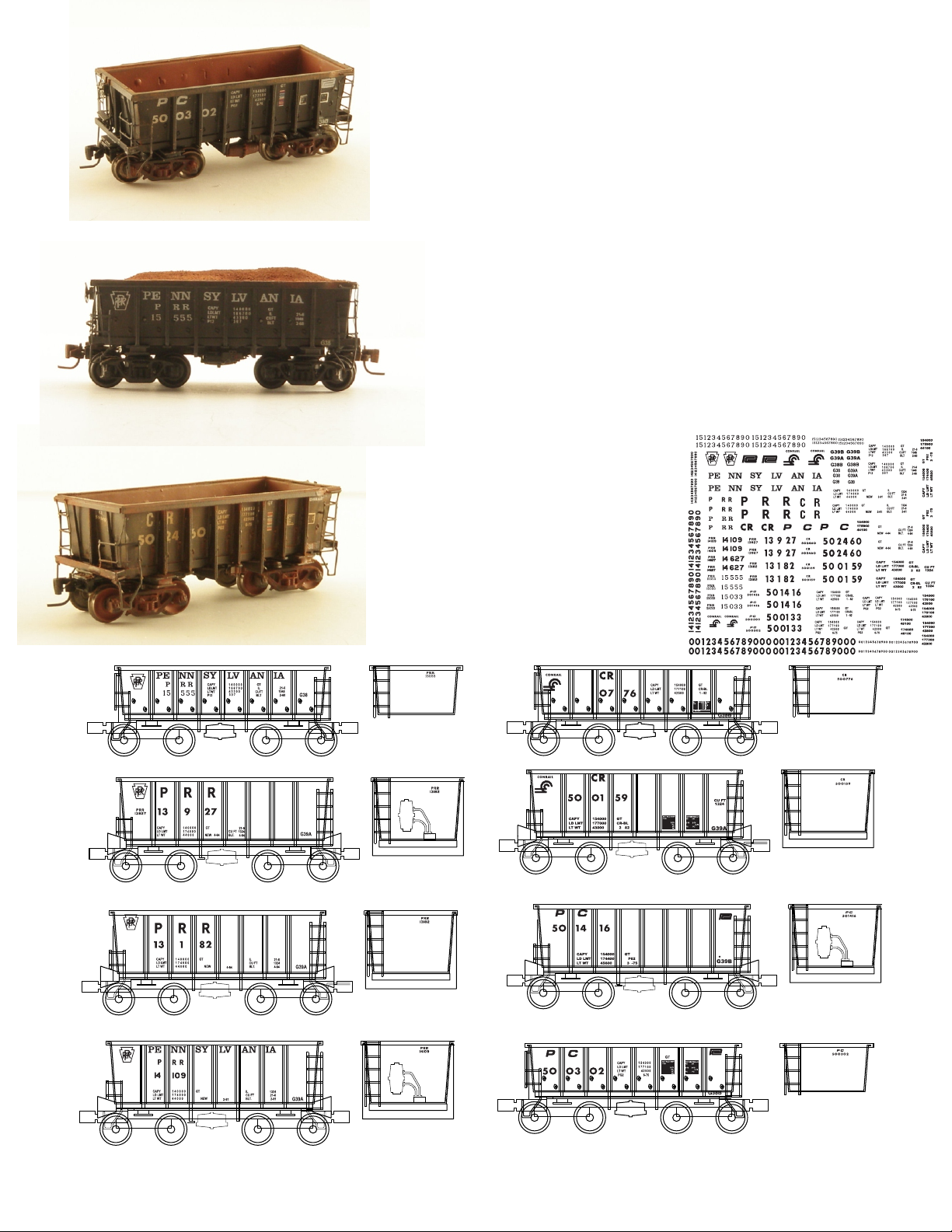
Note: Always Consult actual photos and railroad drawings for the most accurate paint colors, graphics and
decal placement.
Prior to painting and applying decals, thoroughly clean the model with mild
soap such as Dawn. If you soldered your kit, soak the model in acetone,
then wash with soap and water.
My recommendation for colors are a gloss black, and for the later Conrail
units, Red Oxide. Remember, these units saw years of service and were
usually quite beat up and dirty, so don't be hesitate to weather your ore car
either.
For great pictures of the Conrail and Penn Central cars, visit Conrail
Historical Society website.
Unfortunately, there are not many photos of the G38 in PRR paint schemes.
However, if you search, PENNSY RAILCAR RESTORATIONS LLC, you will
find some nice photos of a recently restored G38 Jennie for referance.
If you are building Conrail and Penn
Central cars the decals do not include
lube plates ,repacked bearing markings or
ACI labels all of which are available from
Microtrains.
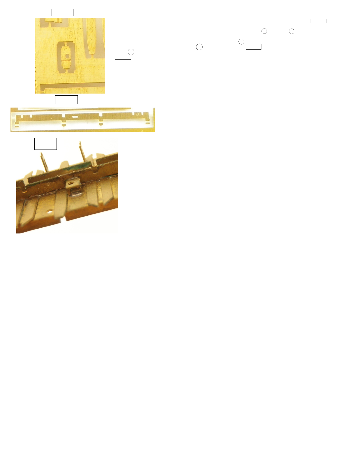
I have added a bracket for the brake cylinder to sit onto so it is easier to get it at the right height. FIG. 25
This new part located at the upper right hand side of the etch above parts H below part V .
With this I have added a two new slots as well one in the floor E located on the same side as the brake
cylinder and triple valve and now a single H has a horizontal slot FIG.26 that will line up with new slot in
the floor E .
In FIG. 27 you can see what the new assembly looks like.
This new part will come into play at step 15.
FIG. 25
FIG. 26
FIG.27
Popular Toy manuals by other brands


Phoenix Model
Phoenix Model westland lysander instruction manual

LRP
LRP Disco Hornet user guide

Massoth
Massoth Piko VT 11.5 TEE manual

Horizon Hobby
Horizon Hobby blade 230 s instruction manual

Miniature Aircraft USA
Miniature Aircraft USA X-cell WHIPLASH Nitro Assembly instructions

LeapFrog
LeapFrog Alphanet Pal Parent guide & instructions


