Air Creation Skypper 582 S User manual

GDMMTA582-1G Version 0010 1
Maintenance Manual
Trike Type :
l
l.
.s
s.
.t
t.
.
S
SK
KY
YP
PP
PE
ER
R
5
58
82
2
/
/
5
58
82
2
S
S
Aérodrome de Lanas, 07200 Aubenas, France
Telephone: +33 (0)4 75 93 66 66 • Fax: +33 (0)4 75 35 04 03

GDMMTA582-1G Version 0010 2
1 Table of Contents
1Table of Contents................................................................... 2
2Amendment Record Sheet .................................................... 4
2.1 Table of Amendments.......................................................................... 4
2.2 Amendments........................................................................................ 4
3Introduction............................................................................ 5
3.1 Skills..................................................................................................... 5
3.2 Tools .................................................................................................... 5
3.3 Air Creation Directives ......................................................................... 6
3.4 Units..................................................................................................... 6
3.4.1 Use of Metric/Imperial Units...................................................................................6
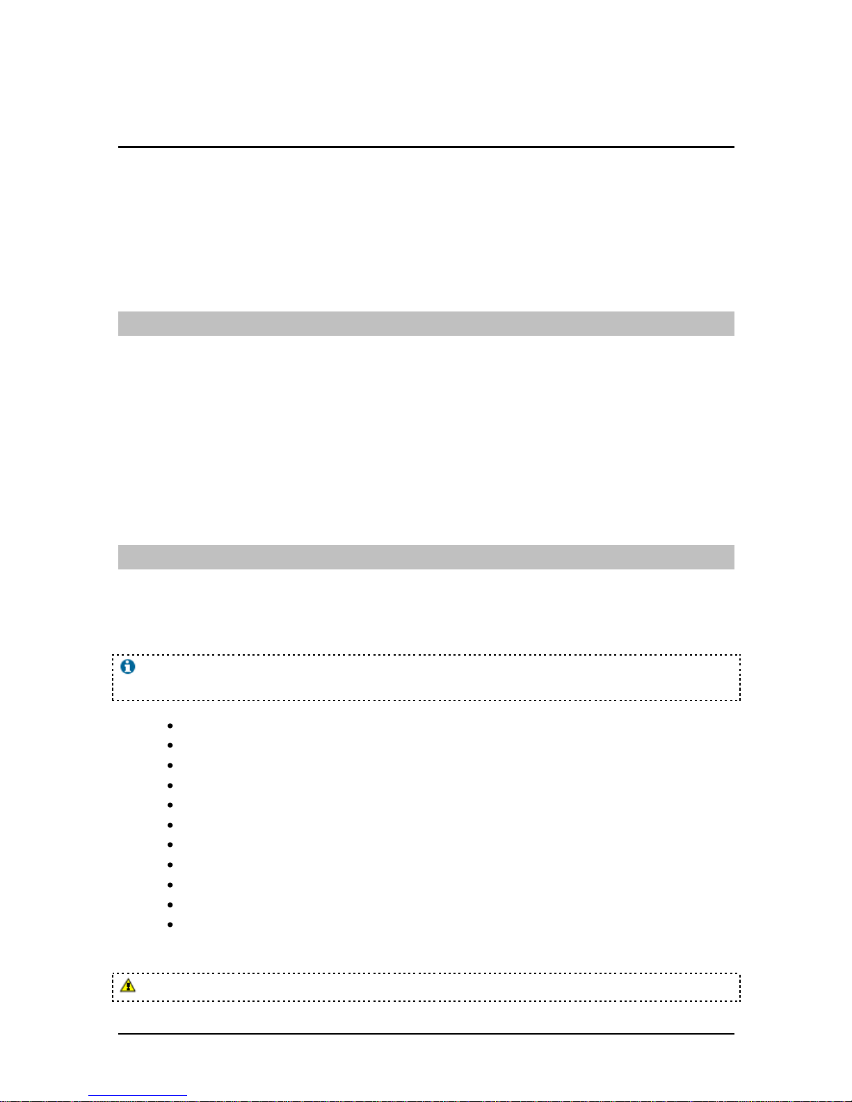
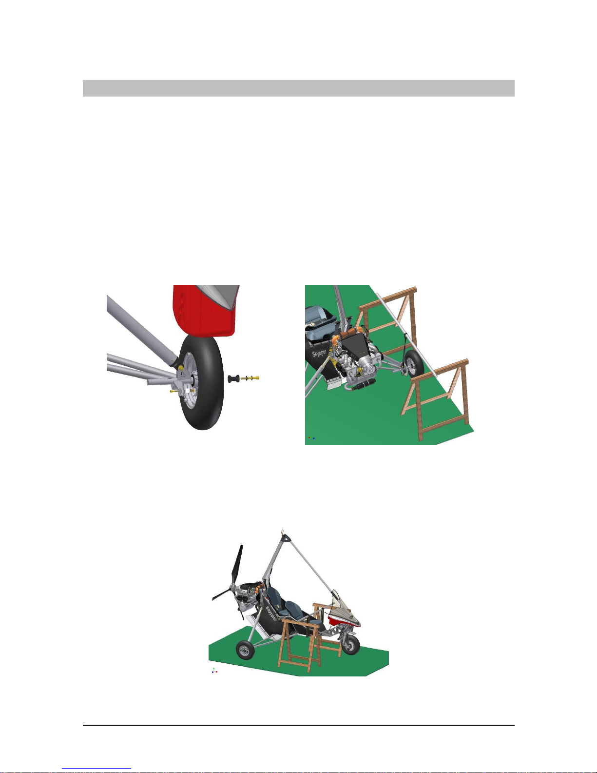
3.5 Lifting & Shoring................................................................................... 7
3.5.1 Lifting the Entire Trike ............................................................................................7
3.5.2 Lifting One Rear Wheel..........................................................................................7
3.5.3 Lifting the Front Wheel ...........................................................................................7
3.6 Transportation & Storage..................................................................... 8
3.6.1 Towing....................................................................................................................8
3.6.2 Taxiing....................................................................................................................8
3.6.3 Ground Transportation ...........................................................................................8
3.6.4 Long-Term Hangarage...........................................................................................8
4Servicing................................................................................. 9
4.1 General ................................................................................................ 9
4.2 Replenishing ........................................................................................ 9
4.2.1 Fuel System Replenishment ..................................................................................9
4.2.2 Fuel Sampling/Draining..........................................................................................9
4.2.3 Coolant Replenishment........................................................................................10
4.3 Tire Inflation ....................................................................................... 10
4.4 Instrumentation .................................................................................. 10
5Maintenance Checks............................................................ 11
5.1 General .............................................................................................. 11
5.2 Time Limits......................................................................................... 11
5.3 Scheduled Maintenance Checks........................................................ 11
5.3.1 Trike Maintenance Schedule................................................................................12
5.3.2 Powerplant Maintenance Schedule......................................................................13

GDMMTA582-1G Version 0010 3
5.4 Unscheduled Maintenance Checks.................................................... 14
5.4.1 General.................................................................................................................14
5.4.2 Inspection after Heavy Landing............................................................................14
5.4.3 Checking for Deformation.....................................................................................14
5.4.4 Inspection after Heavy Turbulence.......................................................................14
6Standard Practices –Airframe............................................ 15
6.1 Torque & Safety................................................................................. 15
6.1.1 Torque Procedures...............................................................................................15
6.1.2 Safety Procedures................................................................................................15
6.2 Inspection Notes ................................................................................ 16
6.2.1 General Maintenance...........................................................................................16
6.2.2 Periodic Maintenance...........................................................................................19
7Appendix............................................................................... 45
7.1 Maintenance Operation Board ........................................................... 45

GDMMTA582-1G Version 0010 4
2 Amendment Record Sheet
2.1 Table of Amendments
Amendment date
Affected sections
Affected pages
Date inserted
Signature
2.2 Amendments
The information in this manual is based on the data that was available at the time of its
publication. The latest amendments to this manual will be issued on the Air Création
website (http://www.aircreation.fr) in PDF format. This should be printed out and added
to the manual. The amendment table should at that time be updated with the appropriate
details and date. Therefore it is important for operators to check the website regularly for
any amendments that have been made. If any errors or omissions are found in this manual
please advise the factory.

GDMMTA582-1G Version 0010 5
3 Introduction
This manual contains factory recommended procedures and instructions for ground
handling, servicing and maintaining the Tanarg trike. The procedures described are to be
used in addition to the particular governing body regulations for each country where the
aircraft is being flown.
The operator is directed to reference the wing maintenance manual for any issues that are
related to the wing component of the aircraft.
3.1 Skills
It is assumed that only people with an adequate skill level will perform maintenance on
this aircraft. A sound understanding of mechanical systems, sufficient experience with
the necessary tools and procedures and knowledge of the specific flight mechanics of
weight-shift controlled aircraft is required –as the continuing airworthiness of the aircraft
relies on the competence of the person performing maintenance. If there are any doubts
regarding the required and appropriate maintenance, an Air Creation technical station
should be contacted for the correct procedures and/or servicing.
All maintenance and repairs should be carried out in accordance with good aeronautical
practices.
3.2 Tools
There are no specialized tools (except for the air shock absorbers) needed for the
maintenance described in this manual. Following is a list of the type of tools that may be
required.
Loctite® will be required in certain locations and should always be replaced after
disassembly.
Loctite® 243, 270, 638 for the frame section.
The Rotax Maintenance Manual gives a list of consumable materials in section 2.5.
Open ended Imperial Spanner set
Open ended Metric Spanner set
Torque wrench (10 –250 in.lb.)
Air Pump (Schrader Style Valve)
Various petroleum lubricants
Dry Lubricant –lubricant which doesn’t attract dust after application.
Tie wire, and tooling
Hex key set
Various general care items
This list may not be comprehensive.
Specialized pumps must be used for the air shocks –pressures up to 600 psi exist.

GDMMTA582-1G Version 0010 6
3.3 Air Creation Directives
The information in this manual needs to be followed, and it is not acceptable to make
changes to the materials and/or physical features of this aircraft.
Air Creation will, from time to time, issue airworthiness directives, which detail any
changes to the maintenance manuals, Pilot’s Operating Handbook, or any other
details that Air Creation deems necessary for owners to be notified of.
The web address for Air Creation directives is:
http://www.aircreation.fr
It is the responsibility of the operator to keep up to date with any Rotax directives
through the Rotax website.
3.4 Units
3.4.1 Use of Metric/Imperial Units
This Service Manual uses the metric unit system as the basic system of measurement.
Where common usage or available instrumentation refer to, the Imperial system, both
units are quoted. The following conversion factors are presented as a ready reference to
the conversion factors that have been used in this manual.
1 Pound (lb) = 0.4536 Kilogram (kg)
1 Pound per sq in (psi) = 6.895 Kilopascal (kPa)
1 Inch (in) = 25.4 Millimeters (mm)
1 Foot (ft) = 0.3048 Meter (m)
1 Statute mile = 1.609 Kilometers (km)
1 Nautical mile (NM) = 1.852 Kilometers (km)
1 Millibar (mb) = 1 Hectopascal (hPa)
1 Millibar (mb) = 0.1 Kilopascal (kPa)
1 Imperial gallon = 4.546 Liters (I)
1 US gallon = 3.785 Liters (I)
1 US quart = 0.946 Liter (I)
1 Cubic foot (ft3) = 28.317 Liters (I)
1 Degree Fahrenheit (F) = (1.8 X C) + 32
1 Inch Pound (in lb) = 0.113 Newton Meters (Nm)
1 Foot Pound (ft lb) = 1.356 Newton Meters (Nm)

GDMMTA582-1G Version 0010 7
3.5 Lifting & Shoring
The Trike may be lifted using the main attachment point for the wing or alternatively
parts of the base may be lifted for local maintenance such as changing tires.
3.5.1 Lifting the Entire Trike
The entire Trike may be elevated from the ground using the main attachment point, the
aircraft should be elevated no more than is necessary.
3.5.2 Lifting One Rear Wheel
Dismount the wheel fairing. While reassembling,
the bolt M8x65 must be glued with Loctite® ref.
270 (strong lock wire). See Figure 3-1.
Lift the trike by the undercarriage (See Figure 3-2.
Method applicable with the wing assembled).
Figure 3-1
Figure 3-2
3.5.3 Lifting the Front Wheel
Lift the front of the trike using the passenger foot rest (See Figure 3-3). Method feasible with the wing
assembled).
Figure 3-3

GDMMTA582-1G Version 0010 8
3.6 Transportation & Storage
Moving the trike is a simple operation due to its light weight and maneuverability. One
person can move it. If the front of the trike is lifted from the ground it is important to
prevent the propeller from touching the ground.
3.6.1 Towing
Pulling the trike with or without the wing is facilitated by lifting the front wheel. The
front wheel is lifted by hand by means of the fiberglass console above the nose wheel.
The trike can also be pushed using the fairing in front of the nose wheel, and using a hand
on the steering pedals inside the pod for directional control.
3.6.2 Taxiing
Taxiing of the trike may be performed with or without the wing. Braking and steering are
achieved by means of the front wheel. The trike should never be taxied with excessive
speed.
Taxiing is a part of the training necessary for flying this aircraft. If a maintenance
engineer without trike flying experience is working on the trike he should push the trike
and not taxi it, as the control sense may be different to what he is accustomed to.
3.6.3 Ground Transportation
The trike may be transported overland on a suitable trailer. During transport the trike base
should be firmly held at both the front and the rear to prevent movement. Tie down straps
should be used with a ratchet system so preload can be applied; this allows the tires to be
compressed slightly so as to firmly hold the base in place during transport.
3.6.4 Long-Term Hangarage
Full covers for the trike are available from Air Creation for long term Hangarage.
The Rotax manual should be consulted for long term storage.

GDMMTA582-1G Version 0010 9
4 Servicing
4.1 General
This chapter provides servicing procedures necessary to replenish or service the aircraft
and its equipment as required.
The operational integrity of the aircraft systems can be seriously impaired if
contaminated fuel, oil, fluids and lubricants are used or if they do not meet the required
specifications. Mixture of various brands and types of materials is undesirable and should
be avoided wherever possible. Specified lubricants will meet requirements for extreme
hot or cold temperature operations. Use of substitutes or other lubricants may cause
malfunction, or excessive wear.
4.2 Replenishing
4.2.1 Fuel System Replenishment
Fuel Specification
The Skypper has a single fuel tank, capacity 55 L. Fill to the neck of the fuel entrance.
The Rotax 582 engine uses a mixture of oil and gas for lubrification. Refer to the Rotax
manual section for engine fuel mixture specifications that apply to the region where the
aircraft is being flown.
Due to higher lead content in AVGAS, the wear of the valve seats and deposits in
the combustion chamber will increase. Therefore, use AVGAS only if the other fuel
types are not available.
Special instructions and service intervals are specified when using Avgas. If Avgas
is used, the Rotax web site should be referenced for maintenance requirements.
4.2.2 Fuel Sampling/Draining
There is a hose and drain cock on the base of the fuel tank behind the back seat, which
may be used to check the quality of the fuel, and to drain fuel if necessary. It is especially
important to remove any water from the system.
Checking the fuel
The fuel is checked for water and contaminants by draining a sample of the fuel into a
clear glass container. Once a sample has been taken the quality of the fuel can be checked
by looking for any water at the bottom of the glass, and checking visually for any other
contaminants.
If the fuel has been sitting for an extended period without use it may be advisable to
replace it with fresh fuel.

GDMMTA582-1G Version 0010 10
Draining the Fuel
Ensure that a suitable receptacle is found for the fuel to be drained, position the drain
cock above the receptacle and depress the drain cock. Ensure that there are no ignition
sources and that the fuel is disposed of correctly.
4.2.3 Coolant Replenishment
Coolant Specification
Consult the Rotax manual for the correct type of coolant.
Rotax recommends a two year or 200-hour replacement intervals for coolant.
4.3 Tire Inflation
The recommended tire inflation pressure is between 1 and 1.2 bars for both the front and
rear tires. Lower pressure favors comfort and improves the ride on soft surfaces. Higher
pressure reduces takeoff distance on hard surfaces. When checking the tire pressures the
opportunity should be taken to examine the tires for wear, cuts, bruises, slippage and
other defects.
4.4 Instrumentation
There are no user serviceable parts in any of the instrumentation for this aircraft; any
maintenance required should be carried out by an approved service centre.

GDMMTA582-1G Version 0010 11
5 Maintenance Checks
5.1 General
This section sets forth each mandatory replacement time, structural inspection interval,
and related structural inspection procedure required.
The time limits and maintenance schedule provided are in addition to any regulation of
the governing body of the country where the aircraft is flown.
The pilot of the aircraft must ensure that all required maintenance is carried out and
documented in the correct manner.
5.2 Time Limits
Extreme operating conditions and any extreme loads will reduce the time limits for
components and the fatigue life of the airframe. The fatigue life of these components is
dependent upon rigid adherence to maintenance schedules. Air Creation will from time to
time amend these maintenance checks as the service history of the aircraft evolves. It is
the responsibility of the pilot to ensure compliance with new directives. (Information is
available on the website http://www.aircreation.fr).
The following components are time-limited and should be overhauled or replaced as
indicated. This table may be updated to include more components in the future as
airworthiness directives are amended.
Trike Component Life
Component
Life
Hang bolt
300 Hrs
Pylon
1500 Hrs
Front tube
1500 Hrs
Trike structure
6000 Hrs
Fuel and oil hoses
5 years or replace during engine overhaul
Engine and accessories
As specified by Rotax
Propeller
As specified by manufacturer Arplast
BRS Rocket
As specified by BRS
5.3 Scheduled Maintenance Checks
Your ultralight should be maintained in accordance with the following schedules.
Within these schedules the following codes are used:
Code:
1. Lubricate, clean and service.
2. Check as directed.
3. Check for insecurity, cracks, wear and faulty operation.
4. Remove, inspect and replace if necessary.
5. Recommend replacement or overhaul.
6. Mandatory replacement

GDMMTA582-1G Version 0010 12
5.3.1 Trike Maintenance Schedule
Item
Maintenance Requirement
Hours of Operation
25
50
75
100
1 yr
125
150
175
200
2 yrs
225
250
275
300
3 yrs
Trike base &
landing gear
All structural members and welds for cracks, dents,
corrosion or deformation
2
3
2
3
2
3
All fasteners for security, condition or fretting
2
3
2
3
2
3
All rig/unfix connectors, rings and clips
2
4
2
4
2
6
Hang point area for condition
3
3
3
Hang bolt
2
4
2
4
2
6
Front mast brace
2
3
2
3
2
3
Instrument console for security and cracks
2
3
2
3
2
3
Wheels spats for mud, security and cracks
3
3
3
3
3
3
3
3
3
3
3
4
Pivot points
3
3
3
Rear suspension swing arms and struts
3
3
4
Rear shock absorbers
2
2
5
Steering head for condition (distortion/cracking), free
movement and play
1
1
4
Main and nose wheels
2
2
4
Wheel bearings for play and freedom
2
2
4
2
Wheel Rims
2
3
2
3
2
3
Tires pressure and wear
2
2
2
2
2
2
2
2
2
2
2
2
Brakes for correct operation
2
2
2
2
2
2
Brake Pads and assembly
2
3
2
3
2
3
Seats and attachments
2
3
2
3
2
3
Safety harness for damage, deterioration and security,
latches and inertia reel for faulty operation
2
2
2
Hand and foot controls for smooth operation.
Adjustment of cables
2
2
2
Parking brake mechanism, adjustment of cables
3
3
3
ASI Pitot and pressure instruments for leaks and proper
working
2
2
2
Parachute installation and repack
(See parachute manual)
2
2
2
Propeller
Blades for nicks and abrasion
2
2
2
2
2
2
2
2
2
2
2
2
Mounting bolts and nuts
2
2
2
2
2
2
2
2
2
2
2
4
Hub section for cracks, deformation
2
2
2
2
2
2
2
2
2
2
2
4
Protective blade tape
2
2
2
2
2
2
2
2
2
2
2
2
Blade pitch, balance and tracking
2
2
2

GDMMTA582-1G Version 0010 13
5.3.2 Powerplant Maintenance Schedule
The following engine maintenance schedules are of a general overview nature. The Rotax
engine Maintenance Manual should be used for specific maintenance required for the
engine.
Disconnect spark plug leads prior to all maintenance and inspection.
Item
Maintenance Requirement
Hours of Operation
25
50
75
100
1 yr
125
150
175
200
2 yrs
225
250
275
300
3 yrs
Engine
Loose bolts
2
2
2
2
2
2
2
2
2
2
2
2
Cylinders, fins
3
3
3
Rubber mounts
2
3
2
3
2
3
Engine Platform, Mounting plates for cracks
2
3
2
3
2
3
Ignition Harness
3
3
3
Battery straps and connections
3
3
3
All wiring for condition and security
2
2
2
Fuel sample from tank drain
2
2
2
2
2
2
2
2
2
2
2
Fuel lines routed properly (free from abrasion, heat and sharp
edges)/fittings tight, condition
2
2
2
3
2
2
2
3
2
2
2
3
Fuel tank and mountings, leaks, cracks and abrasion
3
3
3
Flush out tank
2
Fuel filter for debris
2
2
2
2
2
2
2
2
2
2
2
2
Throttle cables
3
3
3
Air filter
2
2
2
2
2
2
Muffler and exhaust Tubing for cracks
2
2
2
2
2
2
2
2
2
2
2
2
Muffler springs and rubber mounts
2
2
2
2
2
2
2
2
2
2
2
2
All switches condition and operation.
2
2
2
Pylon warning lamp
2
2
2
Carburetors admission rubber
2
2
2
4
2
2
2
4
2
2
2
4
Operation of all gages
2
2
2
Tachometer operation
2
2
2
Hour meter operation
2
2
2
Radiator mounts
2
2
2
2
2
2
Cooling system hoses
2
2
2
2
2
2
2
2
2
2
2
2
Expansion tank level
2
2
2
2
2
2
2
2
2
2
2
2
Ground run at full throttle, static RPM
2
2
2

GDMMTA582-1G Version 0010 14
5.4 Unscheduled Maintenance Checks
5.4.1 General
Unscheduled maintenance is required due to abnormal loads such as severe turbulence or
heavy landings. The pilot is responsible for identification of these extreme operating
conditions and identification of the affected components. Where damage is found further
checks should be carried out upon areas that may also be affected.
Thorough checks should also be carried out after transportation of the aircraft, and after
extended storage periods.
5.4.2 Inspection after Heavy Landing
Check shock absorbers for normal operation and correct length of the sliding tubes.
Check all attachment points and members of the suspension system, rear landing gear and
front fork. Check all welded lugs for bending or cracking of paint, which may indicate
permanent deformation of the area. If any permanent deformation is identified then a
more rigorous inspection of the rest of the aircraft is necessary, as permanent deformation
indicates that extreme forces have been experienced by the aircraft.
5.4.3 Checking for Deformation
A straight edge may be used on the tubing to ascertain straightness.
Attachment Points
Check attachment points of the wing to the base, including the main hang bolt, wheel
axles and bearings. The wing should also necessarily be checked after any heavy landing
because the forces are transmitted through the wing structure.
Check the main structure including the upper beam, landing gear attachment points and
engine mount.
Check that all other components attached to the base are in place and properly secured.
Seat Frame
If the airframe has experienced unusual loads then the seat frames should be checked
thoroughly. The weight of the pilots during impacts may damage the seat frame.
5.4.4 Inspection after Heavy Turbulence
Check all components attached to the base are in place and properly secured, any other
items that may have shifted due to in flight movement should also be checked on a
regular basis.
Turbulence is more likely to structurally affect the wing of the aircraft rather than the
trike. The Wing Maintenance manual should be consulted for instructions that pertain to
the wing.

GDMMTA582-1G Version 0010 15
6 Standard Practices –Airframe
6.1 Torque & Safety
This chapter provides standard torque values and safety procedures that are to be used in
all areas of the aircraft unless otherwise specified. The use of these standard values and
procedures will ensure the security of installation and prevent overstressing of
components.
6.1.1 Torque Procedures
Correct torque of fasteners is critical, if a bolt or fastener is too loose it may cause
unnecessary movement resulting in wear or fatigue, while over tightening may cause
tensile failure of the bolt, or crushing of components.
General Torque Procedures
Definition of “Just not loose”
A definition of torque has been made for the assembly of this trike which has been called
“Just not loose”, a setting which is used to achieve the best combination of strength
characteristics of the tubing while not allowing any vibration or relative movement of the
bolt in the axial direction. In practice this means that the nut shall be tightened adequately
to ensure that each of the components that are held by it are in contact with each other,
and then approximately ¼ turn more should be made. The resulting fit should not allow
any axial movement of the bolt in its location, but will allow rotation (using fingers) of a
held component to be achieved with approximately 20mm of lever arm.
In general, standard torque values will not be applicable, because of the nature of
the thin wall aluminum and steel tubing that is used to construct the majority of the
trike structure. Never tighten nuts so that the tubing is deformed from its circular
cross sectional shape.
Always have at least one full thread showing past any Nylok nut that is used.
Where stainless steel washers are used, the rounded edge should be placed
towards the aluminum tube, if any, or towards other aluminum part, if not.
General Torque Exceptions
1. Joints with hinges or bearings, where free operation is necessary.
2. Bolts, nuts and screws that attach plastic or fiberglass or aluminum tube components, where the
softer material would be damaged by high torques.
3. Engine bolts are to be torqued to the engine manufacturer’s specifications, and may need to be
sequenced.
6.1.2 Safety Procedures
Nylstop nuts
Nylstop nuts are used throughout the airframe. Nylstop nuts may not be reused.
Loctite
On any bolt that does have or not a Nylstop type locking mechanism, Loctite 243 should be used
to prevent premature loosening.

GDMMTA582-1G Version 0010 16
6.2 Inspection Notes
Air Creation Ultralights have been designed to permit easy inspection, and operators
should have no difficulty in assessing problems or recognizing damage if visual checks
are carried out correctly.
Maintenance checks may require partial disassembly of the aircraft. Inspection should
include a thorough visual check of the condition of the component and the attachment
point in adequate lighting conditions. Cleaning of the component may be required for
proper inspection. Significant scratches, cracks, galling or any other mechanical wear of
the component is reason for replacement. The Pilot's Operating Handbook outlines
checks required prior to each flight.
General care should include:
Washing down the tube work with warm water and a mild detergent followed by rinsing with
fresh water.
Fabric sponged with warm water and a mild detergent and rinsed with fresh water.
The fairing and wheel spats washed and polished using shampoo and polish. Treat all exposed
metal components (including the engine but excluding brakes) on the trike frame (only) with a
dewatering compound such as WD40. This guards against corrosion and makes cleaning much
easier.
Rust Proofing
Apart from the consequences of heavy landing, or of exceeding flight limitations, the
major factors requiring attention are corrosion, fatigue and wear.
The Skypper frame is mostly made from stainless steel with the exterior protected with
powder coat paint for rust proofing.
There are no known fatigue problems with Air Creation trikes, but excessive loads and
vibration can weaken the structure. Regular inspection for hair-line cracks in areas under
high stress, such as bolt holes, tube junctions, etc is recommended.
Some components can be replaced with ease, for difficult repairs or if the repair process
is not fully understood consult your Air Creation Technical station or Air Creation
factory.
6.2.1 General Maintenance
This section provides details necessary to carry out routine scheduled periodic
maintenance on the Skypper airframe and is to be read in conjunction with the
maintenance schedules (5.3.1).
Battery Service
A 12V sealed electrolyte battery is equipped and requires no upkeep. It is located inside
the instrument console.
Airframe Lubrication
Most of the pivots on the trike don’t require lubrication, except the front steerer pivot and
bearings (refer to drawing YO11100). Each of the wheels on the trike have fully sealed
bearings in place that should not require user service as they have been lubricated and
sealed by the manufacturer.

GDMMTA582-1G Version 0010 17
If no lubrication interval is specified for a component, lubricate as required and when
assembled or installed.
Cables
Control cables on the trike base include throttle cables, choke cables, steering cables and
brake cables. They need to be checked regularly for excessive friction and wear. The
cables have an internal low friction sleeve and must not be lubricated, because this will
attract dust and create more friction. Wear is most likely to occur at the ends of the cables
at the attachment points.
If wear or excessive friction is present, the cable must be replaced.
Air Filter
Dust and dirt that make their way into the engine are probably the greatest cause of
premature engine wear. The condition of the air filter should be checked each 25 hours as
per the maintenance schedule, and if extreme operating conditions are experienced they
should be checked more frequently. Also check the condition of the air filter after any
extended hangarage.
Air Filter Service Instructions
These service instructions apply to K&N air filters.
1. Tap the element to dislodge any large embedded dirt, and then gently brush with a soft bristle
brush.
2. Spray K&N air filter cleaner liberally onto the entire element and let soak for 10 minutes.
3. Rinse off the element with low-pressure water. Tap water is OK. Always flush from the clean side
to the dirty side. This removes the dirt and does not drive it into the filter.
4. Shake off all excess water and let the element dry naturally.
Do not use compressed air, an open flame or other heat sources. Compressed air
will create holes in the element while excess heat will cause the cotton filter to shrink
Apply K&N air filter oil to the filter after it is dry. Apply the oil along the top and
bottom of each pleat. Wait 20 minutes and re-oil any white spots still showing.
Cleaning
Do not use petroleum products or any highly flammable substances for cleaning. Do
not attempt to wash an engine that is still hot or running. Allow the engine to cool
fully before cleaning. Perform all cleaning operations in a well ventilated work area,
preferably outside, and ensure that personal protective clothing is worn and that fire
fighting safety equipment is readily available.

GDMMTA582-1G Version 0010 18
Particular care should be given to electrical and electronic equipment before
cleaning. Solvent should not be allowed to enter this equipment. Electric/electronic
components should be protected before saturating the engine with solvent. Any oil,
fuel, and air openings on the engine and accessories as well as the BRS parachute
should be covered with a thin plastic film before washing the engine with solvent.
Caustic cleaning solutions should be used cautiously and should be neutralized after
use.
Windshield
The windshield is made from a polycarbonate material and therefore a certain amount of
care is required to keep it clean and in good condition. The following procedure is
recommended.
1. Flush with clean water to remove excess dirt, bugs and other loose particles.
2. Wash with mild detergent and warm water. Use a soft cloth or sponge, do not rub excessively.
3. Rinse thoroughly, and then dry with a clean moist chamois cloth. Do not use volatile solvents such
as gasoline, alcohol, benzene or most commercial window cleaning sprays, as they will adversely
affect the plastic.
Painted Surfaces
The painted exterior surfaces of the aircraft can be washed using a mild detergent and
water, alternatively an automotive liquid detergent may be used.
Engine
An engine and accessories cleaning should be performed regularly to remove any oil,
grease, and other residue. Periodic cleaning allows proper inspection of the engine
components and can be an aid to discovering defects during inspection as well as
reducing the potential for an engine fire during aircraft operation.
The engine may be washed down using a suitable solvent, and then dried thoroughly.
Propeller
The propeller should be cleaned occasionally with water and a mild detergent to remove
dirt, grass and bug stains. The opportunity should be taken to visually check the condition
of the propeller during cleaning.
Upholstery and Interior
The Pod area should be vacuumed out to remove all loose Dirt/Gravel etc. The seat is a
structural part of the airframe and care should be taken to avoid any substance that will
degrade the webbing material, vacuuming is recommended for the upholstery.

GDMMTA582-1G Version 0010 19
6.2.2 Periodic Maintenance
This section provides information necessary for periodic maintenance of the Skypper
trike and should be used conjointly with the upkeep schedule.
Fuselage structure
The fuselage structure of the Skypper is made from two main assembled components that
define the main frame and from the upper beam This does not include the landing gear.
The structure is made mainly from stainless steel.
Main Frame
No particular maintenance is required, excepted the periodic checks for security, bending,
corrosion and cracks.
Front Tube
The front mast brace is the stabilizing member that joins the front of the trike to the top
of the Mast.
The Front mast brace is mainly constructed of 2017A Aluminum. An internal safety
cable provides for the unlikely event of the tube failure.
Mast
The mast is built of stainless steel.
The trike base is attached to the wing using a bolt that attaches to the Wing U bracket.
The attachment arrangement allows the mast to move forwards/backwards and sideways
relative to the hinge point. There is also the safety cable inside the upper beam to provide
for the unlikely event of the main attachment failing.
For instructions regarding the attachment and maintenance of the main bolt, refer to the
wing maintenance manual and the Pilot’s Operating Handbook.
Aerodynamic Fairings
The instrument console is the aerodynamic fairing on the aircraft. A cockpit fairing is
optional. They are constructed from fiberglass and polyester composite material, and
attached to the aircraft via bolts and brackets. The latter are attached to the main
structure.
When checking the spats and other fiberglass areas, ensure that they are free of
cracks, crushing and delamination that may cause them to come loose.
Check the spats for mud, grass or dirt and clean the inside from debris, if necessary.
Each of the fairings should be checked regularly to ensure that the bolts are secure, and
that the fiberglass to which it is attached is in good condition.
The wheel spats are attached to the frame using the brackets on the inside and outside of
the rear wheels. They are held in place with bolts and washers, which are important to
prevent the composite from being damaged.

GDMMTA582-1G Version 0010 20
The vertical stabilizer spats consist of two wheel spats with fins that protrude from the
top surface, and into the airflow, providing yaw stability at high speed. The structural
integrity of the spats is important for the wheel operation, and for ensuring that the outer
wheel nut is secure. They should be checked every 25 hours, as noted in the maintenance
schedule, as well as after any hangarage, or transport to check for impact damage that
may have occurred.
Fiberglass Repair
The fiberglass components may be repaired using polyester resin and fiberglass mat, or
chopped strand mat which is probably the preferable choice for easy thickness build up.
Make sure that the surfaces to be repaired have been correctly prepared for adhesion. Full
repair instructions for the fiberglass components are beyond the scope of this manual,
there are many good texts available for practical composite repairs.
Some guidelines for repairs:
Repair thickness should at least equal original material thickness in all cases, preferably half on
the inside of the damage and half on the outside.
For attachment points the repair thickness should be increased by fifty percent.
Repairs should overlap damage by at least 35mm on all sides.
Repairs are prohibited within a radius of 150mm of the Pitot tube.
Repairs in the vicinity of the Pitot must maintain the original profile or the repair will adversely
affect airworthiness.
Windows
The windshield of the Skypper is basic and should be cared for as per the instructions
covered in section 4.20.10 General maintenance –Windshield.
If the windshield becomes damaged it should be replaced. Contact an Air Creation dealer.
Instrument Brackets
All of the instruments are attached to the aircraft via the instrument panel, which is
attached to the Pod Fairing area. This panel is attached using screws to hold it in place.
Landing gear
The Skypper trike base landing gear assembly consists of a tricycle type undercarriage.
The landing gear is non retractable.
Front
The front landing gear is attached to the main frame through plates and bolts assembly.
The front suspension, steering and braking assembly is manufactured from aluminum and stainless
steel. It is a “pusher” fork type assembly with welded lugs for all attached parts.
Rear
The rear suspension layout consists of tubular main struts for the rear suspension, welded drag link
and rear strut. These are attached to the wheels and the frame via fittings. The fittings are welded
and bolted to the struts and drag link.
The rear suspension incorporates air shocks that allow pneumatic adjustment of the “spring rate”
and fluid flow damping.
Check
With the weight removed from each wheel, check that each of the components is not
loose. Also check each of the bearings, tire wear and the condition of the brake line.
Table of contents
Other Air Creation Aircraft manuals

Air Creation
Air Creation GTE Trek 503 Instructions for use

Air Creation
Air Creation FUN 14 Manual

Air Creation
Air Creation iFUN 16 Manual

Air Creation
Air Creation iFUN 13 SP Manual

Air Creation
Air Creation XP 12 Manual

Air Creation
Air Creation Pixel 303 XC Manual

Air Creation
Air Creation BioniX 15 Owner's manual

Air Creation
Air Creation FUN 450 Manual

Air Creation
Air Creation iFun XL Owner's manual

Air Creation
Air Creation BioniX2 13 User manual