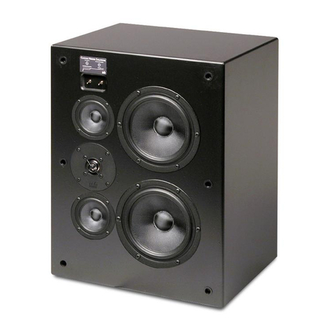
PSB CSIW SUB10 User manual

CSIW SUB10
OWNER’S GUIDE
www.psbspeakers.com

IMPORTANT SAFETY INSTRUCTIONS
1. Read these instructions.
2. Keep these instructions.
3. Heed all warnings.
4. Follow all instructions.
5. Do not use this apparatus near water.
6. Clean only with dry cloth.
7. Do not block any ventilation openings. Install in accordance
with the manufacturer’s instructions.
8. Do not install near any heat sources such as radiators, heat
registers, stoves, or other apparatus (including amplifiers) that
produce heat.
9. Do not defeat the safety purpose of the polarized or grounding-
type plug. A polarized plug has two blades with one wider
than the other. A grounding type plug has two blades and
a third grounding prong. The wide blade or the third prong
are provided for your safety. If the provided plug does not fit
into your outlet, consult an electrician for replacement of the
obsolete outlet.
10. Protect the power cord from being walked on or pinched
particularly at plugs, convenience receptacles, and the point
where they exit from the apparatus.
11. Only use attachments/accessories specified by the manufacturer.
12. Use only with the cart, stand, tripod, bracket, or
table specified by the manufacturer, or sold with the
apparatus. When a cart is used, use caution when
moving the cart/apparatus combination to avoid
injury from tip-over.
13. Unplug this apparatus during lightning storms or when unused
for long periods of time.
14. Refer all servicing to qualified service personnel. Servicing is
required when the apparatus has been damaged in any way,
such as power-supply cord or plug is damaged, liquid has been
spilled or objects have fallen into the apparatus, the apparatus
has been exposed to rain or moisture, does not operate
normally, or has been dropped.
15. The apparatus shall not be exposed to dripping or splashing
and that no objects filled with liquids, such as vases, shall be
placed on the apparatus.
16. WARNING: To reduce the risk of fire or electric shock, this
apparatus should not be exposed to rain or moisture.
17. The mains plug or an appliance coupler is used as the
disconnect device, the disconnect device shall remain readily
operable.
The lightning flash with arrowhead symbol within an
equilateral triangle, is intended to alert you to the
presence of uninsulated “dangerous voltage” within the
product’s enclosure that may be of sufficient magnitude
to constitute a risk of electric shock to persons.
The exclamation point within an equilateral triangle
is intended to alert you to the presence of important
operating and maintenance (servicing) instructions in the
literature accompanying the product.
Notice of FCC Compliance
Warning: Changes or modifications to this unit not expressly
approved by the party responsible for compliance could void the
user’s authority to operate the equipment.
NOTE: This equipment has been tested and found to comply
with the limits for a Class B digital device, pursuant to Part
15 of the FCC Rules. These limits are designed to provide
reasonable protection against harmful interference in a residential
installation. This equipment generates, uses, and can radiate radio
frequency energy and, if not installed and used in accordance
with the instructions, may cause harmful interference to radio
communications. However, there is no guarantee that interference
will not occur in a particular installation. If this equipment does
cause harmful interference to radio or television reception, which
can be determined by turning the equipment off and on, the user is
encouraged to try to correct the interference by one or more of the
following measures:
• Reorient or relocate the receiving antenna.
• Increase the separation between the equipment and receiver.
• Connect the equipment into an outlet on a circuit different from
that to which the receiver is connected.
• Consult the dealer or an experienced radio TV technician for help.
Notes on environmental protection
At the end of its useful life, this product must not be
disposed of with regular household waste but must
be returned to a collection point for the recycling of
electrical and electronic equipment. The symbol on the
product, user’s manual and packaging, point this out.
The materials can be reused in accordance with their
markings. Through re-use, recycling of raw materials,
or other forms of recycling of old products, you are
making an important contribution to the protection of
our environment.
Your local administrative office can advise you of the
responsible waste disposal point.

Introduction
PSB subwoofers are designed to provide the flattest possible frequency response, full bass extension, low distortion and high output.
Beyond these characteristics there are a few other parameters that we feel are very important in the design of a subwoofer.
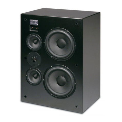
The CSIW SUB10 is an in-wall subwoofer which is designed for new frame and drywall construction.
The installation is a two stage process:
1. Pre Drywall Stage
2. Post Drywall Stage
Required Items:
Step 1: Installing the subwoofer cabinet
For stud wall constructed on 16” centres
Stage 1 – Pre Drywall
The subwoofer cabinet is designed to fit between two adjacent studs on standard 16” (40cm) spacing. Attach Bracket A to the top and the
bottom of the subwoofer cabinet. Position the ends of the brackets outboard of the side of the cabinet to be even with the front panel of
the cabinet. Using appropriate wood screws, fasten the cabinet to the stud wall.
Installing the subwoofer cabinet on 16” centre studs
x4

26
For stud wall constructed on larger than 16” centres
For stud walls exceeding 16” (40 cm) spacing, cross braces must be used. The vertical distance between the two cross braces must be
27½”. The subwoofer driver opening should be located at the bottom of the box. The cross braces must be even with the backside of the
stud wall. This assumes that the wall is a standard 2” x 4” construction method and crossbraces are 2” x 4”, set against the bacside of the
stud.
Attach Bracket B to the top and the bottom of the subwoofer cabinet. Position the ends of the brackets inboard of the side of the cabinet
to line up with the front faces of the cross braces. Using appropriate wood screws, fasten the cabinet to the cross braces.
For stud walls constructed on larger than 16” centres
Step 2: Carefully Remove Hole Cover
Note: Do not discard the hole cover. It will need to be reinstalled prior to the drywall stage.
x4

Step 4: Reinstall the Hole Cover
Step 3: Connect Subwoofer cable
Routing the Subwoofer Cable
With the subwoofer cabinet installed in the wall, the cable from the CS 500W Subwoofer Amplifier can be routed through the wall and
into the cabinet via the cable entry on the bottom of the cabinet. Secure the cable so that it cannot rattle against the studding or drywall
panels and tighten the cable nut to secure the cable to the cabinet.
Connecting the subwoofer cable
Securing the subwoofer cable
Wire from PSB
CustomSound CS500W
Subwoofer Amplifier
Note: The dotted line on the Grill cover is to be
used as the guide for the drywall cutout.
The diameter of the cutout area is 300mm (11.8”)

Required Items:
Stage 2 – After Drywall Completion
Step 5: Install the Driver
remove woofer opening cover
The subwoofer driver is installed after the installation of the drywall and final decorating has been completed. Remove woofer opening
cover.
Connect the speaker wires to the driver. Note: the positive and negative wires have specific connectors and will only connect
to the subwoofer driver in one way. Do not force the incorrect wire on the connector onto the driver.
Connecting the speaker wires to the driver

For square grills, place the square bracket against the driver, then
install the magnetic trim ring using the four (4) supplied screws.
Place the magnetic square grill onto the trim ring.
Attaching the square grill
Step 6: Install the Grill
Determine whether the round or square grills will be used.
For round grills, install the magnetic trim ring using the four (4)
supplied screws. Place the magnetic round grill onto the trim ring.
For square grills, place the square bracket against the driver, then
install the magnetic trim ring using the four (4) supplied screws.
Place the magnetic square grill onto the trim ring.
The square grill has been designed with screw
holes which allow the installer to fasten the grill
directly to the drywall, ensuring a tight seal and
preventing vibration. Included are four short
drywall screws for this application.
Note: If additional screws are required, do not
use screws which are longer than the thickness
of the drywall.
Place the driver into the cabinet opening and secure using the eight (8) supplied screws.
Installing the subwoofer driver
x8
x4
x4
Attaching the round grill

19-029 CustomSound CSIW SUB10 Owner’s Manual
Step 7: Subwoofer Amplifier Settings
The PSB CS 500W Subwoofer Amplifier has been designed to match perfectly with the CSIW SUB10 subwoofer. The sonic profile of the
CSIW SUB10 is stored within the amplifier.
Note: When setting up the amplifier, it is necessary to set the profile to CSIW SUB10. Do not play the subwoofer until the profile has been
set. Refer to the CS 500W owner’s manual for detailed instructions.
Note: The use of any other subwoofer amplifier without the proper calibration may result in unsatisfactory performance or cause damage
to the subwoofer itself. In such case, the warranty would be considered null and void.
Table of contents
Other PSB Speakers manuals

PSB
PSB ALPHA PS1 User manual
PSB
PSB CHS80 User manual
PSB
PSB CustomSound CW28 User manual
PSB
PSB Custom Sound m6x6.1 User manual
PSB
PSB CW600E User manual
PSB
PSB CW170FR User manual
PSB
PSB CWS8 Quick start guide
PSB
PSB the CustomSound Series User manual
PSB
PSB Alpha B1 User manual
PSB
PSB CustomSound CW800E User manual

