MEDC DB4 User manual

Cooper MEDC 2011 01/12
Technical Manual for the Speaker DB4
Please note that every care has been taken to ensure the accuracy of our technical manual. We do not, however, accept
responsibility for damage, loss or expense resulting from any error or omission. We reserve the right to make alterations
in line with technical advances and industry standards.

01/12 Cooper MEDC 2011

Cooper MEDC 2011 01/12
English
1.0 INTRODUCTION
This range of loudspeakers, intended for use in potentially explosive gas and dust atmospheres, has a power
rating of up to 25 watts and is suitable for use in all gas groups including hydrogen.
The flamepaths, flare and the body are manufactured completely from a UV stable glass reinforced polyester.
Stainless steel screws and sinter are incorporated thus ensuring a corrosion free product. A tapered Flamepath
is used to overcome the problems of assembly of parallel spigot flamepaths.
2.0 INSTALLATION
General
When installing and operating explosion-protected equipment, requirements for selection, installation and
operation should be referred to eg. IEC60079-14 worldwide and the ‘National Electrical Code’ in North
America. Additional national and/or local requirements may apply.
Ensure that all nuts, bolts and fixings are secure.
Ensure that only the correct listed or certified stopping plugs are used to blank off unused gland entry points
and that the NEMA/IP rating of the unit is maintained. MEDC recommend the use of a sealing compound such
as HYLOMAR PL32 on the threads of glands and stopping plugs in order to maintain the IP rating of the unit.
The unit mounts via 2 off ∅23/64” (∅9mm) mounting holes in the ‘U’ shaped stirrup / mounting bracket.
The holes have been designed to accept an M8 screw or bolt. If required the unit can be initially placed using
the ∅½” (∅13mm) central hole in the mounting bracket. The unit can then be rotated into the correct
orientation and fixed via the other two holes.
When the unit is fixed in the required position, it’s alignment can be adjusted by loosening the two M6 screws which
fasten the mounting bracket to the speaker. The speaker can then be adjusted to the required position and the screws
tightened. The unit should be positioned such that dust/debris or water cannot settle in the re-entrant horn.
MEDC recommend the use of stainless steel screws.
Cable Term nat on
CAUTION: Before remov ng the cover assembly, ensure that the power to the un t s solated.
General
The cover is secured with 6 off M5 cover screws (4.0mm A/F hexagon key). Once the cover fixings are
unscrewed, twist the cover assembly gently clockwise and anti-clockwise, whilst pulling it away from the base.
Remove to gain access to the interior.
Ensure all non-captive fixings are kept in a safe accessible location during cable termination.
Cable termination should be in accordance with specifications applying to the required application. MEDC
recommends that all cables and cores should be correctly identified. Please refer to the wiring diagram
provided with the product.
Ensure that only the correct listed or certified cable glands are used and that the assembly is shrouded and
correctly earthed.
All cable glands should be of an equivalent NEMA/IP rating to that of the speaker and integrated with the
unit such that this rating is maintained.
The internal earth terminal, where fitted, must be used for the equipment grounding connection and the
external terminal is for a supplementary bonding connection where local codes or authorities permit or require
such a connection.
Once termination is complete, carefully replace the cover assembly back onto the body, avoiding damage to
the mating surfaces. Replace the cover screws into the holes in the cover assembly and tighten evenly. Ensure
the O-ring is seated correctly on the cover during re-assembly. Ensure the required maximum gap of 0.15mm
is maintained between the cover and the base once assembled.

01/12 Cooper MEDC 2011
3.0 OPERATION
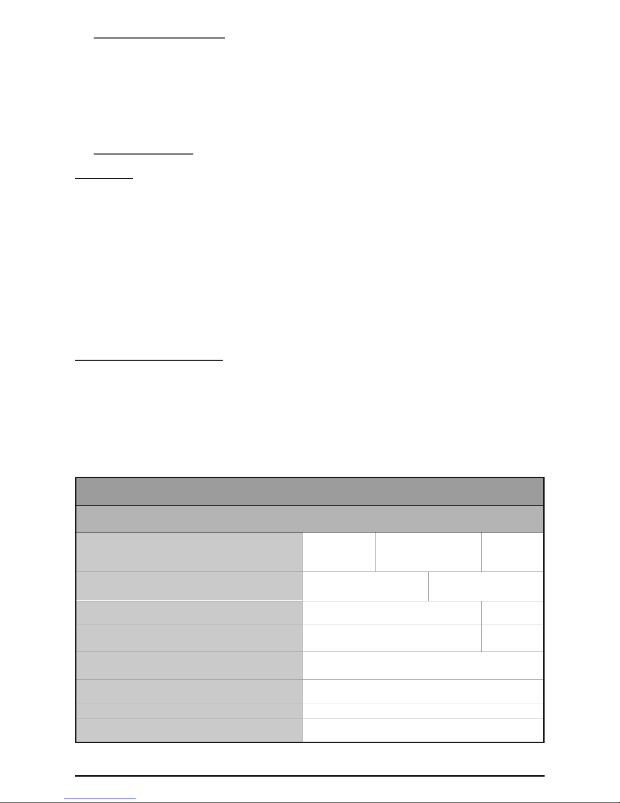
The operating voltage of the unit is stated on the unit label. The speaker is available in 3 standard wattage
ratings from 8 watts to 25 watts. Different sound levels can be obtained by selecting the transformer tappings
in the unit. See table below for details.
GENERAL ARRANGEMENT
4.0 MAINTENANCE
During the working life of the unit, it should require little or no maintenance. GRP will resist attack by most
acids, alkalis and chemicals and is as resistant to concentrated acids and alkalis as most metal products.
However, if abnormal or unusual environmental conditions occur due to plant damage or accident etc., then
visual inspection is recommended.
If the unit requires cleaning, then only clean exterior with a damp cloth to avoid electro-static charge build up.
Repairs should be undertaken by returning the unit to MEDC or by an authorised repairer of Ex equipment.
If a unit fault should occur, then the unit can be repaired by MEDC. All parts of the unit are replaceable.
If you acquired a significant quantity of units, then it is recommended that spares are also made available.
Please discuss your requirements with the Technical Sales Engineers at MEDC.
Power (W)
Transformer
Tappings 25W 15W 8W
1:2 25.015.08.0
2:3 12.57.54.0
3:4 6.05.02.0
1:3 4.04.01.5
2:4 2.02.00.7
1:4 1.00.80.4
Cooper MEDC 2011 01/12
5.0 CERTIFICATION/APPROVALS
Please refer to the marking on the unit for specific approval details
UL listed for use in USA (USL) Class I, Zone 1, AExd IIC T4
and Canada (CNL) Class 1, Div. 2, Groups A, B, C & D
Class II, Div. 2, Groups F & G
UL Standards UL 1480, UL60079-0, UL60079-1, CSA E60079-0, CSA E60079-1
6.0 FUNCTIONAL SAFETY
Introduct on
The DB4 Speaker has been designed for use in potentially explosive atmospheres and harsh environmental
conditions. The glass reinforced polyester enclosures are suitable for use offshore or onshore, where light
weight combined with corrosion resistance is required.
The FMEDA has considered the worst case scenario which includes the Exe Chamber on the rear.
The safety function of the Speaker is to provide an audible warning when required.
Under No fault (Normal) Operating conditions the DB4 Speaker will provide an audible warning when
required.
Under fault conditions the failure mode of the Speaker is a failure to provide an audible warning sound. For
the failure rate associated with this failure mode please refer to the table below.
Assessment of Funct onal Safety
The DB4 Speaker is intended for use in a safety system conforming to the requirements of IEC61508.
Sira Test & certification Ltd has conducted a Failure Modes Effect and Diagnostic Analysis (FMEDA) of the
DB4 Speaker unit against the requirements of IEC61508-2 using a proof test interval of 8760hrs.
The DB4 Speaker is classed as a Type A device.
PROVEN IN USE SUMMARY TABLE
U
T
DB4 SPEAKER
Safety Function of the DB4 Speaker:
To provide an audible warning sound when required’
Architectural constraints:
Type A
HFT=0
SFF = 85.00%
Proof Test Interval
=8760Hrs
MTTR = 8 Hrs
SIL2
Random hardware failures:
!DD = 0
!DU = 4.70E-07
!SD = 0
!SU = 2.86E-06
Probability of failure on demand: PFDAVG=2.06E-03
(Low Demand Mode) SIL2
Probability of Dangerous failure on safety function: PFH = 4.70E-07
(High Demand Mode) SIL2
Hardware safety integrity compliance Route 1H
Systematic safety integrity compliance Route 1S
Systematic Capability SC2
Overall SIL-capability achieved SIL 2 (Low Demand)
SIL 2 (High Demand)

01/12 Cooper MEDC 2011
Cond t ons of Safe Use
The following conditions apply to the installation, operation and maintenance of the assessed equipment.
Failure to observe these may compromise the safety integrity of the assessed equipment:
1. The user shall comply with the requirements given in the manufacturer’s user documentation (This Safety
Manual and Technical manual) in regard to all relevant functional safety aspects such as application of use,
installation, operation, maintenance, proof tests, maximum ratings, environmental conditions, repair, etc;
2. Selection of this equipment for use in safety functions and the installation, configuration, overall
validation, maintenance and repair shall only be carried out by competent personnel, observing all the
manufacturer’s conditions and recommendations in the user documentation.
3. All nformat on assoc ated w th any f eld fa lures of th s product should be collected under a
dependab l ty management process (e.g., IEC 60300-3-2) and reported to the manufacturer.
4. The unit should be tested at regular intervals to identify any malfunctions; in accordance with this safety
manual.
MEDC Stock No.
T TM105-ISS. B
E Web: w
T
m

Cooper MEDC 2011 01/12

Cooper MEDC Ltd, Colliery Road, Pinxton, Nottingham NG16 6JF, United Kingdom.
Tel: +44 (0)1773 864100
E-Mail: [email protected] • med[email protected]
Web: www.coopermedc.com
01/12 Cooper MEDC 2011
MEDC Stock No:
TM105-ISS.B
Other manuals for DB4
3
Other MEDC Speakers manuals


Popular Speakers manuals by other brands


Silvercrest
Silvercrest SLB 1.2 A1 User manual and service information

Monacor
Monacor ETS-8100TW/SW instructions

Maceton
Maceton Lightning 16 quick start guide

Altec Lansing
Altec Lansing INMOTION IMT207 Faq

Fenton
Fenton SBS65 instruction manual

Electro-Voice
Electro-Voice Xi Series Xi-2153A/64F Specifications


