PSC Solar OGM Series User manual

8
1
MPPT Module Type
USER MANUAL
8KVA-12KVA OGM
Series
Hybrid Inverter
Sate
Copyright, copying and plagiarism without any authorization is prohibited
The company is committed to the continuous improvement of the inverter. This information is subject to change without notice. please refer to the actual
product.

8
Contents
1.Product introduction ………………………………………………………1
2. Product features……………………………………………………………1
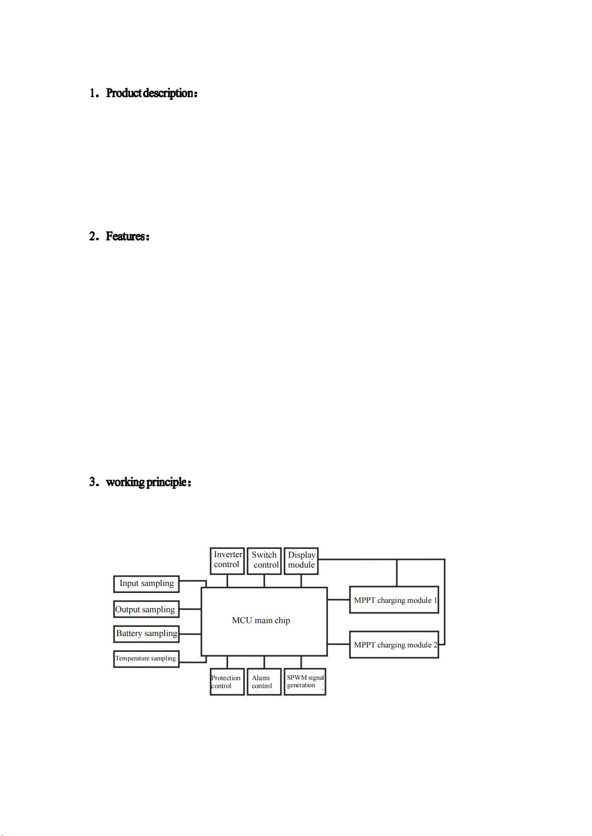
3. Working principle…………………………………………………………1
4. Introduction to working mode ……………………………………………2
5. Appearance introduction…………………………………………………5
6. Installation instructions ……………………………………………………7
7. Operation and maintenance ………………………………………………9
8. Inverter startup procedure ………………………………………………10
9. Emergency shutdown procedure …………………………………………10
10. Operation interface description …………………………………………10
11. Technical parameters …………………………………………………… 16
12. Causes and solutions of common failures ……………………………… 17
13. Packing list ……………………………………………………………… 17
8
2
8KVA-12KVA OGM series MPPT inverter control all-in-one machine is a highly
intelligent product integrating digitization, informationization and networking. It has a
powerful information acquisition system, signal processing system, detection system and
perfect protection system. It is widely used in a variety of electrical environments,
personalized design, and friendly man-machine dialogue. The touch screen LCD is the latest
power display module developed by the company and adopts today's popular intuitive
graphical operation interface. Compared with the general LCD display module, the touch
screen display module has no complicated operation steps. The user can directly click the
analog button on the display to obtain the corresponding information, and the operation is
simple and easy to understand.
2.1. The inverter adopts DSP, MCU and DDC real-time processing all-digital vector
control technology to accurately control various parameters of the machine and fully
control it.
2.2. The combination of advanced IGBT high frequency pulse width modulation
technology (M PPT ) reduces system noise and power loss, ensuring that customers can
obtain high-quality voltage output and the highest benefits under various workload
conditions.
2.3. The output of the machine with isolation transformer and equipped with isolation
transformer will not have DC components in the load, which can effectively protect the
switching power supply of computers, networks and comm unication equipment from DC
current damage. At the sam e time, it can also be used for non-linear loads. It exhibits
excellent dynamic performance, improves the load capacity of the machine, and has good
load compatibility.
2.4. Complete protection functions, with AC input over voltage and under voltage
protection, output over voltage and under voltage protection, output overload short-circuit
protection, battery under voltage warning protection, internal over-temperature protection,
which greatly guarantees the operation of the system Stability and reliability.
2.5. The use of high-power IGBT devices makes the inverter have strong overload capacity
and shock resistance, and at the same time enhances the adaptability to the power grid.
The 8KVA-12KVA OGM series MPPT inverter control all-in-one machine is highly
integrated with digital technology to improve MTBF and reliability. It adopts MCU
high-speed microprocessor control to ensure stable and reliable operation of the equipment.
8
3
4.Work mode introduction:
The 8KVA-12KVA OGM series inverters have two working modes: battery priority mode
(DC Priority) and mains priority mode (AC Priority).
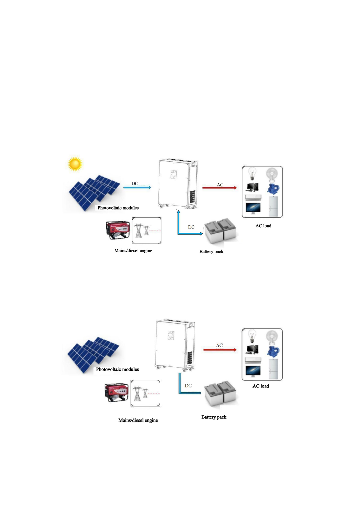
4.1. Battery priority mode(DC Priority):
When the battery voltage is normal, regardless of whether the mains (or diesel engine) input
is normal or not, the inverter works by inverting the battery's direct current into alternating current
to supply power to the load. When the battery voltage is too low, the inverter automatically
switches to the mains ( (Or diesel engine) to supply power to the load, but not to charge the battery.
After the battery is fully charged by the photovoltaic panel, the inverter will automatically switch
to battery inverter to supply power to the load. This mode is suitable for new energy systems such
as photovoltaic power generation and wind power generation.
(1) In battery priority mode, when the photovoltaic panel is generating electricity in sufficient
sunlight, the system works as shown in the figure below:
(2) In battery priority mode, when the photovoltaic panel does not generate electricity at night or
on a cloudy or rainy day and the battery voltage is normal, the system works as shown in the
figure below:
(3) In battery priority mode, when the photovoltaic panel does not generate electricity at night or
on a cloudy or rainy day and the battery is low, the system works as shown in the figure below:
8
4
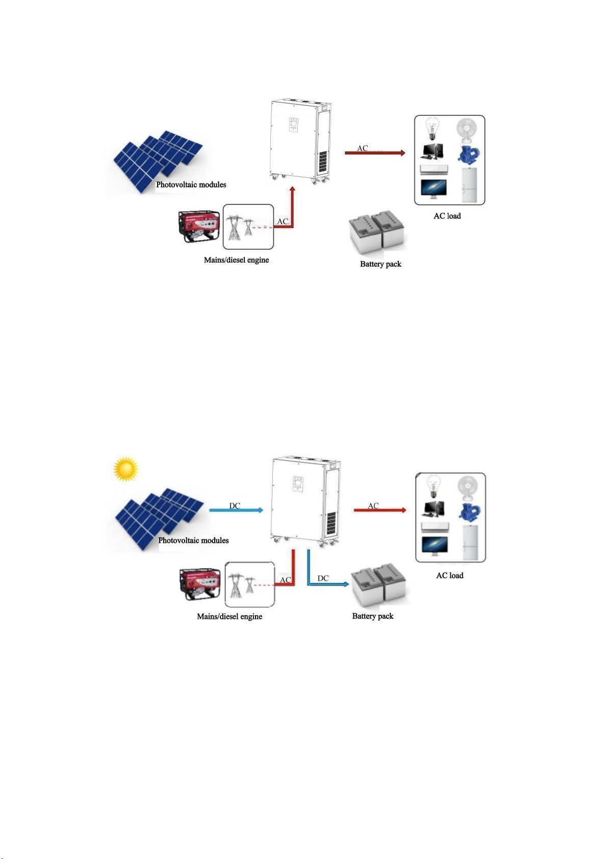
4.2.AC Priority:
When the mains (or diesel engine) input is normal, the inverter works in the mains bypass to
supply power to the load and at the same time to the battery.When the mains power is too
high/low/severe distortion/frequency abnormality/fault and other abnormal conditions, the inverter
will automatically switch to the battery to supply power to the load. After the mains (or diesel
engine) input is normal, the inverter will be reversed. The converter will automatically switch to
the mains bypass to supply power to the load. This mode is suitable for the backup power system,
the inverter is always on, and it is suitable for the unstable mains or the need to ensure the
uninterrupted load to shorten the switching time.
(1) In the mains priority mode, when the photovoltaic panel is fully sunny and the mains input is
normal, the system works as shown in the figure below:
(2) In the mains priority mode, when the photovoltaic panel generates electricity with sufficient
sunlight and the mains input is abnormal, the system works as shown in the figure below:
8
5
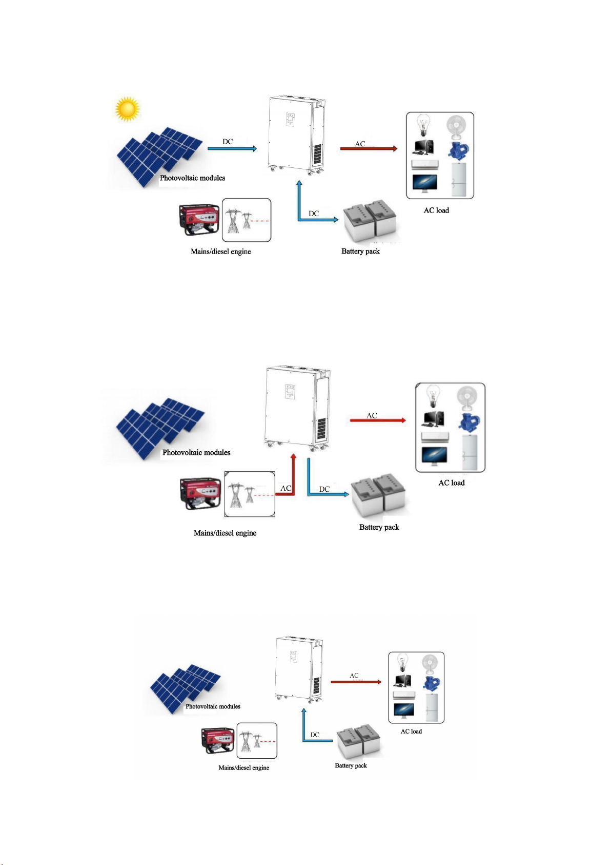
(3) In the mains priority mode, when the photovoltaic panel does not generate power at night or on
a cloudy or rainy day and the mains input is normal, the system works as shown in the figure
below:
(4) In the mains priority mode, when the photovoltaic panel does not generate electricity at night
or on a cloudy or rainy day, the mains input is abnormal and the battery voltage is normal, the
system works as shown in the figure below:
8
6
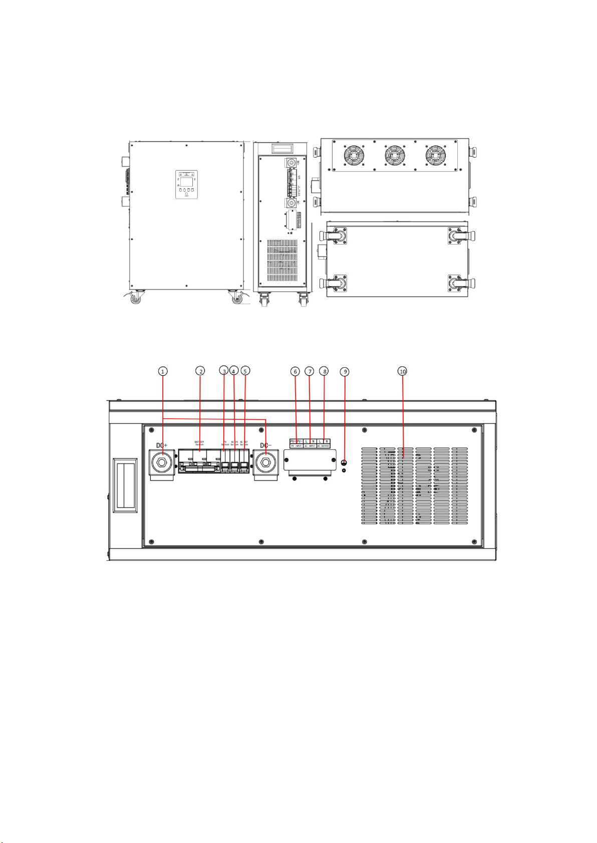
5.Appearance introduction
5.1 Terminal introduction
①DC is the battery input terminal, DC+ is the positive pole, and DC- is the negative pole;
②The battery switch must be disconnected before installation, and the switch can be turned on
after the installation is complete;
③PV Switch is a photovoltaic input switch;
④AC IN Switch is an AC input switch, which needs to be disconnected before installation, and it
can be turned on after the installation is complete;
⑤AC OUT Switch is an AC output switch, it needs to be disconnected before installation, and it
can be turned on after the installation is completed;
⑥PV INPUT is the photovoltaic input terminal, + is the positive pole,-is the negative pole;
⑦AC INPUT is an AC input terminal, which can be connected to the mains for complementation,
and it will not affect the use if it is not connected to the mains;
⑧AC OUT is an AC output port, which can be connected to a load;
⑨is the ground terminal;
⑩Cooling fan;

8
7
6. Installation instructions
Please strictly follow the warnings and operating instructions in the manual and on the
machine and keep this manual properly. Please do not operate this machine before reading all the
safety instructions and operating instructions, otherwise it will damage the equipment and cause
personal safety accidents.
6.1. Unpacking inspection
The inverter power supply has been strictly inspected before leaving the factory, but it may
be damaged during transportation. Therefore, after unpacking, please check whether the following
items are complete and whether the model, power, input voltage, output voltage, etc. are
consistent with the order The specified content matches; if there is an abnormality or the content
does not match, please contact our company as soon as possible.
6.2. Handling
This product should be handled with care during transportation to avoid falling, collision and
strong vibration. It is strictly forbidden to turn the packaging box upside down. Do not lose
accessories, instruction manuals, warranty cards, etc. when unpacking and transporting. In
addition, this product is large and heavy. Please pay attention to safety when handling it to avoid
injury to your body.
6.3. Installation instructions
1. When installing the inverter power supply, it must be done by professionals or with the
assistance of local dealers.
2. Confirm whether the input DC power supply voltage range meets the requirements, ie +15%,
and whether the power supply polarity is correct.
3. Confirm the voltage level of the load equipment, and the power should not be greater than the
rated output power of the inverter power supply.
4. Do not pour liquid into the inverter power supply, or wipe the machine casing with a damp
cloth. The human body cannot be directly when the machine is running
Touch the input and output terminals of the inverter power supply, especially with wet hands,
otherwise it may cause electric shock.
5. If the working environment of the normal inverter power supply needs to be changed, it is not
allowed to change its connection by yourself, and a professional should be
The operator or dealer confirms the operation.
6. The operating environment of the electric power supply should be in a well-ventilated
environment with a temperature range of -25 to 50°C and a relative humidity of 30%-90%.
When using, keep it away from open flames and direct sunlight. No corrosive gas, oil mist, water
splash, salt mist, rain, humidity, and can not operate in condensation and dust environment. If the
altitude is below 1000m, please decide to use|great to use|data to use|drive to use|rate to use|dare to
use|date to use|dream to use|rewrite to use|treat to use if it exceeds this altitude. A certain amount
of heat is normal during use, but the installation environment must be kept clean and clean,
especially not blocking the ventilation holes.
7. Minors are not allowed to use this product.
8. Confirm that the ground wire of the inverter power supply is reliably connected, the live wire
and the neutral wire cannot be reversed, and the wire diameter should meet the conditions for safe
use, The connection line should be as short as possible.
9. Please do not open the inverter power supply case by yourself, otherwise we will not be
responsible for the warranty.
10. No objects can be placed on the top of the equipment; sufficient space for inspection and
repair must be prepared directly in front of and above the equipment, and the power cord must be
wired from the bottom of the machine;
Notice:
A. This product cannot be used for life-sustaining equipment without permission.
B. This inverter power supply is not suitable for ultra-high-precision electronic equipment, it
needs to be confirmed by professional and technical personnel before it can be used
run.
C. If it is used for computer load, the built-in power supply of the computer should be a brand
power supply.
warn!

8
8
It is strictly forbidden to connect the battery in reverse, and it is strictly prohibited to connect the
live wire and the neutral wire in reverse.
It is strictly forbidden to use it in an environment with flammable and explosive gases, and beware
of sparks!
The connection sequence must be the battery first and then the photovoltaic panel. It is strictly
forbidden to reverse the sequence.
6.4. Safety instructions
1. Be sure to read the manual and understand all the contents before use.
2. Do not block the heat dissipation holes of the device with sundries during use to ensure good
ventilation and heat dissipation.
3. Regardless of the working status, please do not remove or connect the equipment cable with
power to avoid danger.
4. The connection cable must choose the appropriate specification, the connection is firm and the
insulation is good.
5. Please do not close any circuit breakers before all equipment is fully connected
6. When inspecting or maintaining the inverter, you must wait for more than 10 minutes after
removing the relevant connecting wires before opening the cover of the device to prevent the
electric charge stored in the capacitor components of the inverter from causing electric shock to
persons.
7. To avoid personal injury and machine damage caused by electric shock, do not open the cover
(shell).
8. It is forbidden to connect the output of the inverter to the mains power grid. The mains line
must be isolated from the inverter line before use, otherwise the inverter will be seriously
damaged.
9. It is strictly forbidden to use it in an environment with flammable and explosive gases or objects,
and beware of flames and sparks.
10. When the AC side of the inverter is loaded, the DC connection must not be directly
disconnected. You must first cut off the DC switch of the inverter and confirm that there is no
voltage before disconnecting the DC connection.
11. When the inverter is live, do not plug or unplug any connectors, and do not open the cover of
the machine!
12. This equipment must not be operated with overload, and equipment failures and damages
caused by overload operation are not covered by the warranty.
6.5Wiring block connection attention:
Before the inverter is installed, disconnect all switches.
According to the picture above, AC INPUT is connected to the mains input (pay attention to the
phase of zero live wire), G is grounding, AC OUTPUT is connected to load appliances (note the
phase of zero live wire), SOLAR PANEL is connected to photovoltaic panels (note the positive
and negative polarity), and BATTERY is connected to the battery ( Pay attention to the positive
and negative polarity), you need to connect the battery first and then the photovoltaic panel;
6.6 Wiring check
Connect all input and output wires, and check the following items:
Whether all the battery cables are connected correctly and in good contact, and the input, output,
and grounding cables are correctly connected to the corresponding terminal block on the device.
6.7. Cable current-carrying capacity parameters: see the table below (subject to
multi-strand copper core cables, unit: mm2)
7. Operation and maintenance

8
9
1. Connect and install the equipment in strict accordance with the relevant operating procedures.
During installation, you should carefully check: whether the wire diameter meets the requirements;
whether the components and terminals are loose during transportation; whether the insulation parts
are well insulated; whether the grounding of the system meets the requirements.
2. It should be operated and used strictly in accordance with the provisions of the product
instruction manual. Especially: Before starting the machine, pay attention to whether the input
voltage is normal; when operating, pay attention to whether the sequence of power on and off is
correct.
3. The equipment has automatic protection for short-circuit, over-current, over-voltage,
over-heating, etc., so there is no need to shut down manually when these phenomena occur; the
protection points for automatic protection are generally set at the factory and do not need to be
adjusted.
4. There is high voltage in the equipment cabinet, and the operator is generally not allowed to
open the cabinet door, and the cabinet door should be locked normally.
5. When the room temperature exceeds 50°C, heat dissipation and cooling measures should be
taken to prevent the equipment from malfunctioning and prolong the service life of the equipment.
6. Regularly check whether the wiring of each part of the equipment is firm and whether there is
any looseness. In particular, carefully check the fan, power module, input terminal, output
terminal and grounding.
7. The operator must be specially trained to be able to judge the cause of the general failure and be
able to eliminate it.
For example, you can skillfully replace fuses, components, and damaged circuit boards. Untrained
personnel are not allowed to operate and use the equipment.
8. Once the alarm is stopped, it is not allowed to turn on immediately. The cause should be found
out and repaired before turning on again.
9. If an accident that is not easy to eliminate or the cause of the accident is unclear, a detailed
record of the accident should be made, and the production factory should be notified in time for
resolution.
10. Virtual connection or damage to the battery pack is one of the main factors causing equipment
failure. It is recommended to check the voltage of the battery and whether the connection
terminals are reliably connected every two months (tools can be used to fasten each terminal), and
remove the rust stains on the terminal in time. Clean the dust inside the equipment regularly, and
disconnect the relevant connecting wires of the inverter during cleaning.
11. When the load is inductive loads such as refrigerators, motors, washing machines, water
pumps, etc., the equipment should be selected at 5-6 times its nominal power, and the load should
be increased one by one. Frequent starting is strictly prohibited.
12. When the inverter fails to work normally, please refer to the instructions in the manual. If it
still cannot be solved, please contact the dealer or the manufacturer as soon as possible. Do not
disassemble the parts by yourself!
8. Start-up procedure of the inverter control integrated machine:
Correctly operating the inverter power supply can better ensure its service life and provide
high-quality input power for your load equipment. The following are the recommended normal
operation steps of inverter power supply for you.
8.1. Normal start-up steps of the inverter power supply
1. Connect the front AC input power;
2. Close the inverter DC input switch (battery switch);
3. After the inverter output indicator INV lights up, close the inverter AC input switch;
4. After confirming that the load can be powered, close the inverter AC output switch;
5. Turn on the load equipment switches one by one;
8.2. Operation steps for normal shutdown of inverter power supply
1. Turn off the load equipment switches one by one;
2. Disconnect the AC output switch of the inverter power supply;
3. Disconnect the AC input switch of the inverter power supply;
4. Disconnect the inverter DC input switch (battery switch);
5. Disconnect the front-level AC input power;
8
10
9. Emergency shutdown procedure:
This operating procedure can only be operated when fire, electric shock, arc or other hazards
occur, but it will cause no danger of AC output.
—— Disconnect all switches downward
Notice:
The company reserves the right not to guarantee the quality of the products in the following
situations.
1. The whole machine and parts have exceeded the free warranty period;
2. Product transportation damage;
3. Incorrect installation, modification or use that is not in accordance with the requirements of the
manual;
4. Exceed the very harsh environment described in this manual;
5. Failure or damage to the machine caused by installation, repair, modification or disassembly by
non-service agencies or personnel of our company.
If the product fails due to the above situation, the customer requires maintenance service. After the
judgment of the company's service department, paid maintenance services can be provided.
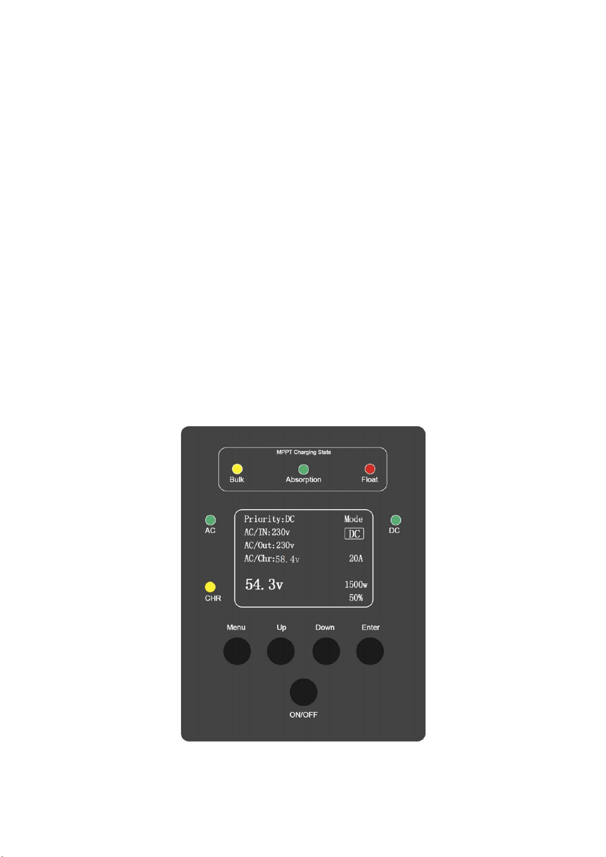
10. Operation interface description:
10.1 Open the main interface
The operation control display panel is located on the front. By operating the control display panel,
you can control and query all parameters, battery status, and alarm information. This series of
inverters can choose whether to need MPPT. The interface with MPPT is shown in Figure 3-1, and
the interface without MPPT is shown in Figure 3-2. The following instructions are introduced in
accordance with Figure 1, as shown in Figure 3-1. The operation control display panel can be
divided into three parts according to functions: MPPT light display, LCD display and menu keys,
and control operation keys. The description of the components of the operation control display
panel is shown in Table 10-1.
Figure 10-1 Operation Control Display Panel (with MPPT)

8
11
Figure 10-2 Operation Control Display Panel (without MPPT)
Table 10-1 Description of the operation control display panel components
explicit
identification
description
explicit
identification
description
Priority
Current priority mode
54.3v
Current battery voltage
AC/IN
AC input value
DC
Current output mode
AC/Out
AC output value
1500w
50%
Current power and load
percentage
Note: The above values are the demonstration values, for reference only
Table 10-2 Key press description:
Key identification
meaning
MENU
Enter the menu
UP
Select up
DOWN
Select down
ENT
Determine or return
ON/OFF
Turn on or turn off,Press the on / off button for 5 seconds.
10.2 LED indicator lamp
Table 10-3 Description of the indicator lamp status
pilot lamp
state
meaning
AC
The yellow
is often
bright
The machine is running and in the main power output mode
The yellow
is not bright
8
12
pilot lamp
state
meaning
DC/INV
Green is
often bright
Battery inverter running in the state of the machine, from the
battery inverter power output
Green, not
bright
CHR
light on
The equipment is charged via the main power supply
MPPT Charging State
Bulk
light on
In fast charge mode
light off
Not under fast charge
Absorption
light on
In equal charge mode
light off
Not in equal charge mode
Float
light on
In float mode
light off
Not in floating charge mode
10.3 Sound alarm (buzzer)
Operation can be accompanied by two different sound alarms as described in Tables 3-4.
Table 10-4 Sound alarm description
alarm call
meaning
Continue to cry
Power boot self-inspection
Two short sounds
Set the save
A short sound
key
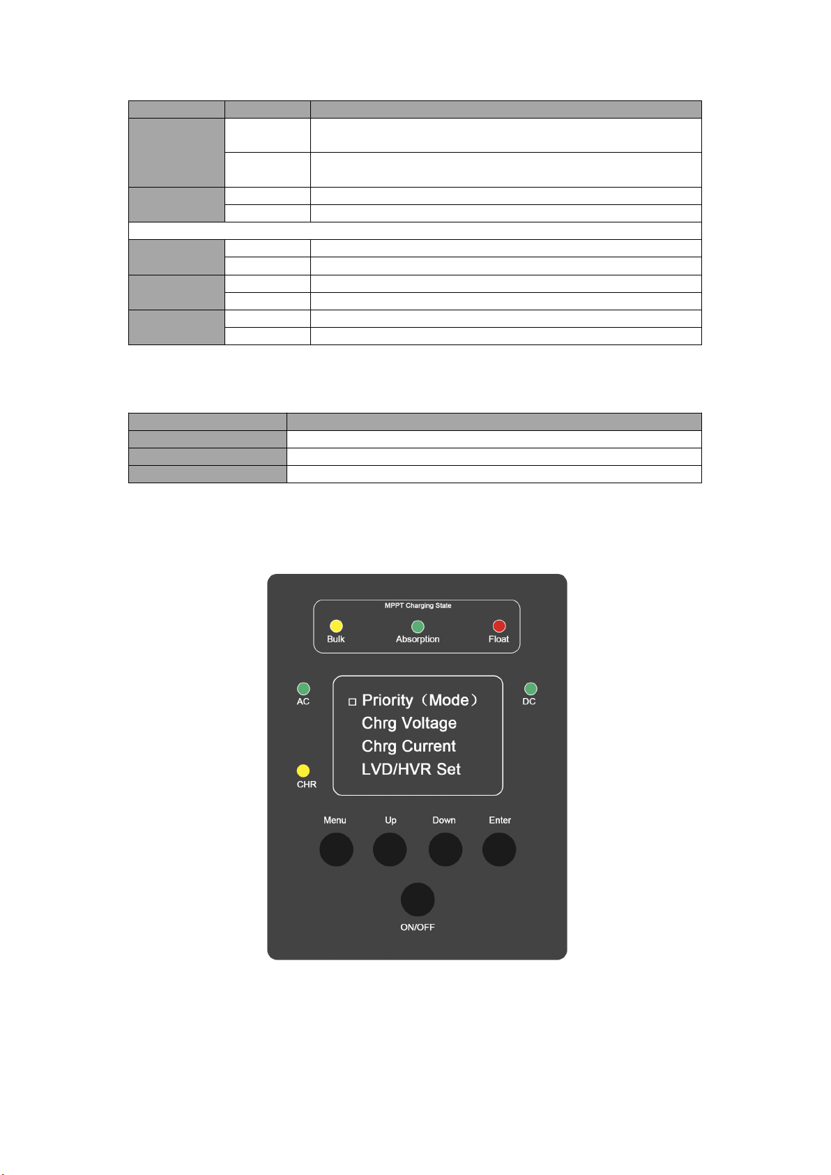
10.3 System settings
(1) Settings: Home-Menu-Enter the System Settings page, select needs and enter by pressing up
and down.
(2) Priority (Mode) settings: Press up and down to select the mode and enter, and then the machine
will restart and run the new mode.
8
13
(3) AC charging voltage setting: Press up and down, which will display in the lower left corner,
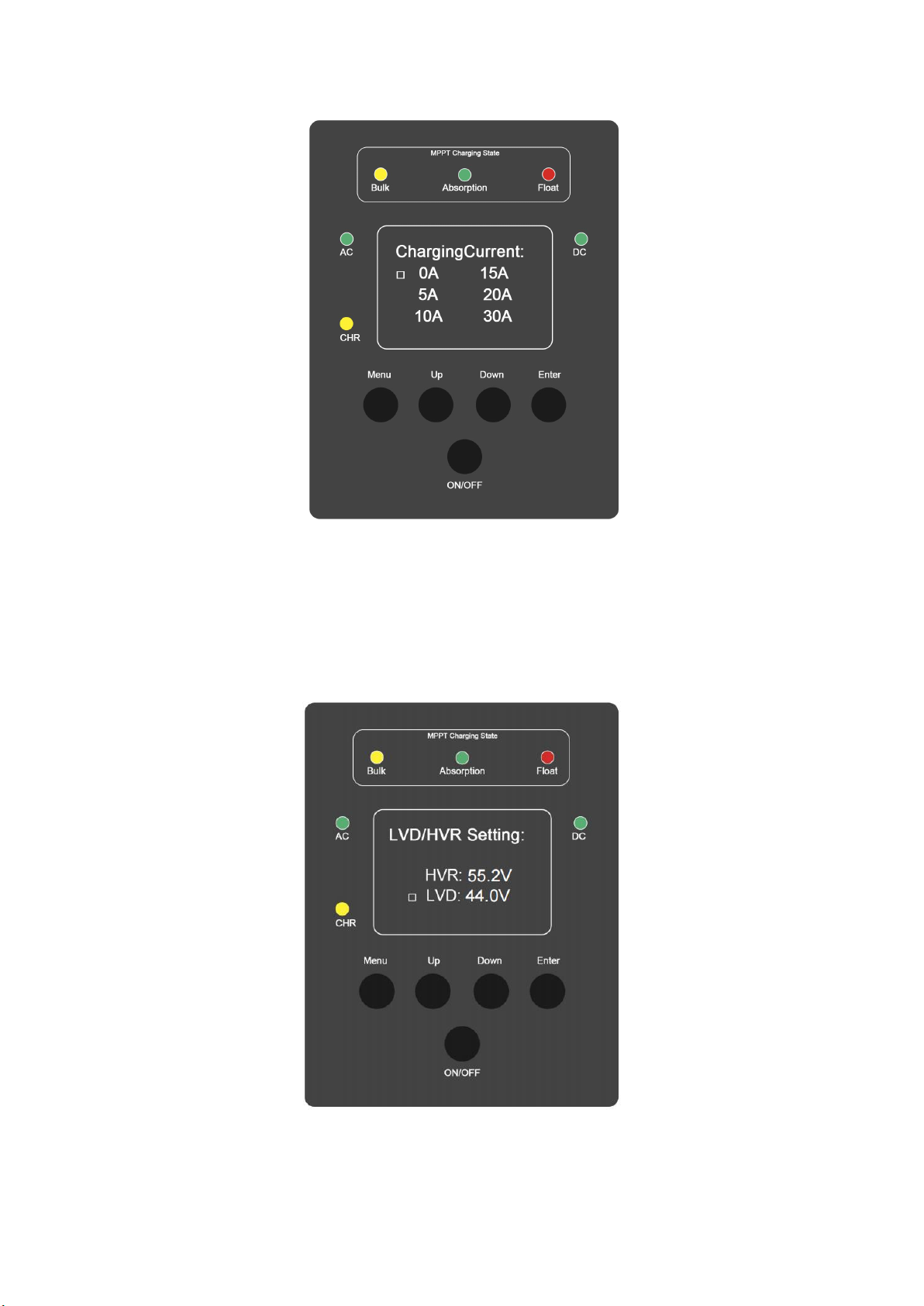
(4) AC charging current setting: press up and down to select the charging current.Choosing an OA
means that charging stops automatically after charging.Press Enter to confirm, and the machine
will restart.
8
14
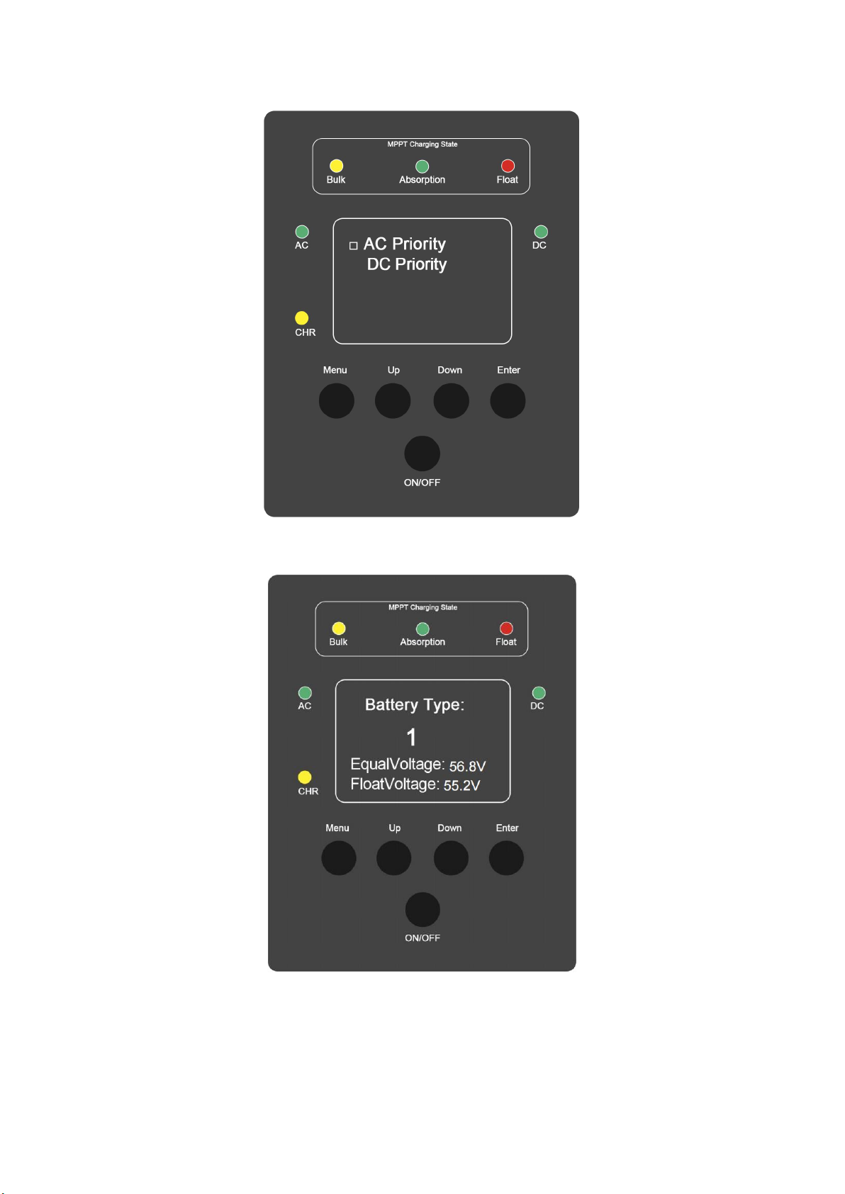
(5) DC priority mode instruction: (battery high voltage automatically changed to inverter, low
voltage to power supply).
In this mode, the inverter preferentially uses a DC power supply (battery), when the battery power
is fully charged by the total or solar power,
Turning to the user setting the HVR, the inverter automatically becomes an inverted output.When
the low power sets the LVD as the user,
Working mode changes to the power output.Press the upper and lower keys to select the voltage,
and the menu sets the HVR and LVD.Then press Enter to confirm, and the machine will restart
and run the new mode.
(6) MPPT charging current setting
Refer to the AC charging settings.

8
15
11.technical parameter
12. The causes and treatment methods of common failures:
Since the inverter itself has complete protection functions, once an abnormality or failure
occurs, the inverter will be shut down or the output will be stopped, and the LCD display will
indicate the corresponding abnormal information and the working status of the inverter
respectively.
Technical Parameter :
Inverter Mode
8KVA OGM
10KVA OGM
12KVA OGM
Rated power
6KW
8KW
10KW
Battery voltage
48V
Chassis size (W * D* Hmm)
580*370*730
740*400*930
Package size(W * D *Hmm)
650*420*840
820*480*1050
Net weight(kg)
65
85
95
Gross weight(kg)
80
100
110
Input
Phase
L+N+G
Mains input range
110V:85~138VAC;220V:170~275VAC
Frequency Range
45Hz~65Hz
Output
Output voltage
Inverter mode: 110VAC/220V±5%; Mains mode:
110VAC/220VAC±10%;
Frequency range(Mains
mode)
Automatic tracking
Frequency range(inverter
mode)
50Hz/60Hz±1%
Over load (Mains mode)
Mains mode: (100%~110%: 10 minutes; 110%~130%: 1 minute;
>130%: 1 second;)
Over load(inverter mode)
Inverter mode: (110%~110%: 30 seconds; 110%~130%: 10 seconds;
>130%: 1 second;)
Current peak ratio
3:1max
Switching time
<10ms (typical load)
Wave
Pure sine wave
Efficient
>85% (80% resistive load)
Protective function
Battery over voltage and low voltage protection, overload protection,
short circuit protection, over temperature protection, etc.
Built~in solar controller (optional)
Maximum charging current
100A
150A
Battery voltage
48V
PV input voltage range
65V ~250V
Maximum photovoltaic
input power
4800W
7200W
Cooling method
Air-cooled
Environmental conditions
Operating temperature
0~40℃(battery life will be shortened in an environment >25℃)
Operating humidity
<95% and no condensation
Operating altitude
<1000m (1% per 100 m, up to 5000 m)
Noise
<58dB (1 meter distance)
Manage
show
LCD+LED
Computer communication
interface
RS232 (optional)
* The above data is for reference, if there is any change, please refer to the actual product.

8
16
When the inverter fails to work normally, please refer to the instructions in the manual. If it still
cannot be solved, please contact the dealer or the manufacturer as soon as possible. Do not
disassemble the parts by yourself!
13.Packing list:
If the user cannot understand the contents of the manual or wants more detailed help when using it,
please contact the dealer or consult our company, we will be happy to serve you.
PSC Solar UK
Physical Office/Warehouse: 41B, Olutoye Cres/Adeniyi Jones, Ikeja,
Lagos State,Nigeria
Phone No.: +2348120855444, +2348123655444
Website: www.pscsolaruk.com Email Address: info@pscsolaruk.com
Failure phenomenon
cause of issue
Approach
In the absence of AC
input, the inverter cannot
start
DC input abnormal
Check whether the connecting wire of the DC
(battery) input is connected correctly, with good
contact and correct polarity, and measure whether
the voltage between the two terminals of the DC
(battery) input is normal.
DC input switch is open
Check the DC input switch
Output overload or short
circuit
Turn off the load and check whether the load cable
is damaged or short-circuited
AC input failed
Abnormal AC input
Check whether the AC input cable is connected
correctly, in good contact and the phase is correct,
and measure whether the AC input voltage and
frequency are normal.
AC input switch is open
Check the AC input switch
Without AC input, the
machine has no AC output
AC output switch is open
Check the AC output switch
DC input over voltage
Discharge the battery to a normal value and then
reconnect and boot
DC input under voltage
Wait for the photovoltaic module to charge the
battery to the normal value, or switch the mains
priority mode to charge the battery to the normal
value, then the output can be restored
Output overload or short
circuit
Turn off the load and check whether the load cable
is damaged or short-circuited
Machine high temperature
alarm
The internal temperature of
the machine is too high
Check whether the fan is faulty and whether the
cooling holes are blocked
Machine overload alarm
Load power exceeds rated
value
Remove non-critical loads
Number
Name
Quantity/Unit
Remark
1
Inverter host
1 set
2
user's manual
1 copy
3
Warranty Card
1 piece
This manual suits for next models
3
Table of contents
Other PSC Solar Inverter manuals


Popular Inverter manuals by other brands


Delta
Delta M Series Operation and installation manual

Centech
Centech 60601 Owner's manual & safety instructions

Tripp Lite
Tripp Lite PowerVerter RV3012OEM Specifications

Delta
Delta M50A-260 Installation and operation manual

Delta
Delta RPI-H3 Operation and installation manual

Delta
Delta RPI-H3 owner's manual