PSC Solar SGS Series User manual

Thank you for purchasing our products
Please strictly comply with all warning notes and operating
instructions in this manual. Keep this manual properly for future use.
Please don’t operate Inverter until you carefully read all the safety
and operating instructions.

Safe declare
Operation safety
1. In the use of the product before, please read “safety declare”, to ensure the correct and safe to use. And please
keep the manual.
2. Pay attention to the all warning when operating, according to the requirements for operation.
3. Avoid direct sunlight, rain or in the wet environment using this equipment.
4. This equipment can not be installed near the heat source area.
5. Placed around the Inverter, should have a safe distance, ensure ventilation. When installation, please refer to
specification.
6. When cleaning, please use the dry goods to wipe.
7. In case of fire, please correct use of dry powder fire extinguisher to extinguish fire. If the use of liquid fire
extinguisher will have a risk of electric shock.
8. Before installation should consider floor bearing capacity on the machine and battery.
Warning users:
This is A level Inverter product, that may cause radio interference in the living
environment, in this case, the users can take adequate measures.
Electrical safety
1. Before starting Inverter, please confirm grounding correctly, and check the wiring and polarity is properly
connected.
2. When Inverter needs to move or to be wiring, please shutdown Inverter and disconnect AC input breaker and
battery breaker, or there is a risk of electric shock.
Battery safety
1. Battery life varies with ambient temperature decreases. Regular replacement of batteries can ensure normal work
of Inverter, and to ensure adequate reserve time.
2. Battery can only be maintained by qualified personnel!
3. Replace the battery, must use the same type and model of the battery, and the number must be the same.
4. Battery to involve a risk of electric shock and short circuit current risk. To avoid electric shock accident, when
replacing the batteries, please observe the following warning:
A. Don’t wear watches, rings or other metal objects;
B. Using the insulated tools;
C. Wear rubber shoes and gloves;
D. Can not put metal tools or metal parts on the batteries.
E. Before removing the battery terminals, must disconnect the load.
5. Please do not burn the battery in the fire, so as not to cause an explosion, endanger the personal safety.
6. Non professionals do not open or damage battery, because the battery electrolyte contains strong acid and other
hazardous substances, the skin and eyes are hurt. Such as accidentally contact with the electrolyte, should
immediately with plenty of water for cleaning, and go to the hospital to check.
7. Please do not use the battery short circuit, will cause electric shock or fire.
Operating environment
1. Operating environment will affect Inverter stability, therefore, please prevent Inverter operating in this
environment:
a. The place beyond rated range (temperature 0-40℃, humidity20-90%);
b. The vibration places;
c. The place contains metal dust, corrosive substances and combustible gas;
2. If inverter do not use in long time, need to store it in dry environment, storage temperature: -25-55℃.

Index
Chapter Ⅰ Product Introduction...........................................................................................................1-4
1.1 Synopsis...................................................................................................................................................................1
1.2 Topology.................................................................................................................................................................1
1.3 Operational principle............................................................................................................................................1-2
1.4 Structure configuration.........................................................................................................................................2-3
1.5 Specification............................................................................................................................................................4
Chapter Ⅱ Installation............................................................................................................................5-8
2.1 Environmental requirements...................................................................................................................................5
2.2 Unpacking...............................................................................................................................................................5
2.3 Mechanical size....................................................................................................................................................5-6
2.4 Transport..............................................................................................................................................................6-7
2.5 Method of fix...........................................................................................................................................................7
2.6 Terminal block connect...........................................................................................................................................8
Chapter Ⅲ Wiring..................................................................................................................................9-
13
3.1 Cable diameter choosing.........................................................................................................................................9
3.2 Cable connection..............................................................................................................................................10-13
Chapter Ⅳ Power On and Debugging................................................................................................14-
15
4.1 Preparation............................................................................................................................................................14
4.2 Function test.....................................................................................................................................................14-15
Chapter Ⅴ LCD panel operation........................................................................................................16-29
5.1 LCD panel........................................................................................................................................................16-18
5.2 Display information details..............................................................................................................................18-20
5.3 System control.......................................................................................................................................................21
5.4 System state......................................................................................................................................................21-23
5.5 System setup....................................................................................................................................................23-28
5.6 Inverter alarm and display................................................................................................................................28-29
Chapter Ⅵ Operate and maintenance guide.....................................................................................30-31
6.1 User Guide.............................................................................................................................................................30
6.2 Maintenance Guide................................................................................................................................................31
Chapter Ⅶ Fault diagnosis.......................................................................................................................32
7.1 Fault diagnosis procedure......................................................................................................................................32
7.2 Fault information of ICON....................................................................................................................................32
7.3 Fault information of buzzer..................................................................................................................................32
7.4 SPD (Surge protect device)...................................................................................................................................32
Appendix Ⅰ Start and shutdown inverter operation process...............................................................33

1
Chapter Ⅰ Product Introduction
1.1 Synopsis
SGS inverter is on/off grid with intelligent energy management, which transfers PV energy to gird or load. With
built-in transformer and advanced DSP-based digital control technology, SGS inverter has high reliability,high
efficiency, isolated stable output, abundant intelligent interfaces and supports any kinds of load.
1.2 Topology
It consists of inverter (DC/AC), STS,built-in MPPT charger,isolated transformer and maintenance switch Q3, input
switch Q1, bypass switch Q2 and output switch Q4.
P1
Q2
Q3
Q4
By pa s s
MPPT Inverter
Isolation
Tr ansf or mer
Static switch
I nput Static switch
Out put swi t ch
Mai nt enance swi t ch
Bypass swi t ch
Sol a r s wi t c h
Out put
Bat t e r y
Solar Input
B1
Battery switch
Figure 1-1 Block diagram of Inverter
1.3 Operational principle
T1
G
E
C
G
E
C
G
E
C
G
E
C
GND
IGBT3 IGBT4
N
N
MANUAL SW ITCH
OUT PU T SW IT C H
IN PUT SW ITC H
G
E
C
G
E
C
IGBT5
SCR2
1
2
3
1
2
3
IN-T
IN-S
IN-R
OU-R
OU-S
OU-T
N
N
N
N
N
Isolation Transformer
SCR 1
SCR3
SCR4
SCR5
SCR6
G
M
E
C
Q1
PV+
PV-
31
2
GND
GND
G
M
E
C
Q1
31
2
GND
GND
SPD
EAR TH
BAT+
BAT-
GND
L1
L2
BATTERY SW IT CH
PV SW ITC H
PV-
EAR TH
BAT CONTACTOR
CHARGE REALY
Figure 1-2 Inverter main circuit schematics
2
Battery is charged by external solar charger. If the grid power is available, DC/AC inverter will feed the energy to
the grid.If the grid power is abnormal, DC/AC inverter will power the load with off-grid function. If the battery
voltage is extremely low, DC/AC will work as a charger to charge the battery.
This DC/AC inverter is based on SPWM/SVPWM control technology with built-in transformer. Grid is totally
isolated form PV input so no insulation fail/big leak current problem.
The SGS inverter adopts the newest TI TMS32028F28234 DSP with abundant functions. It implements power
transform and intelligent energy management while providing RS232/RS485 interfaces.
1.4 Structure configuration
The Inverter system make up of INV, front LCD panel, transformers, breakers, fans, aluminum capacitors and so
on.
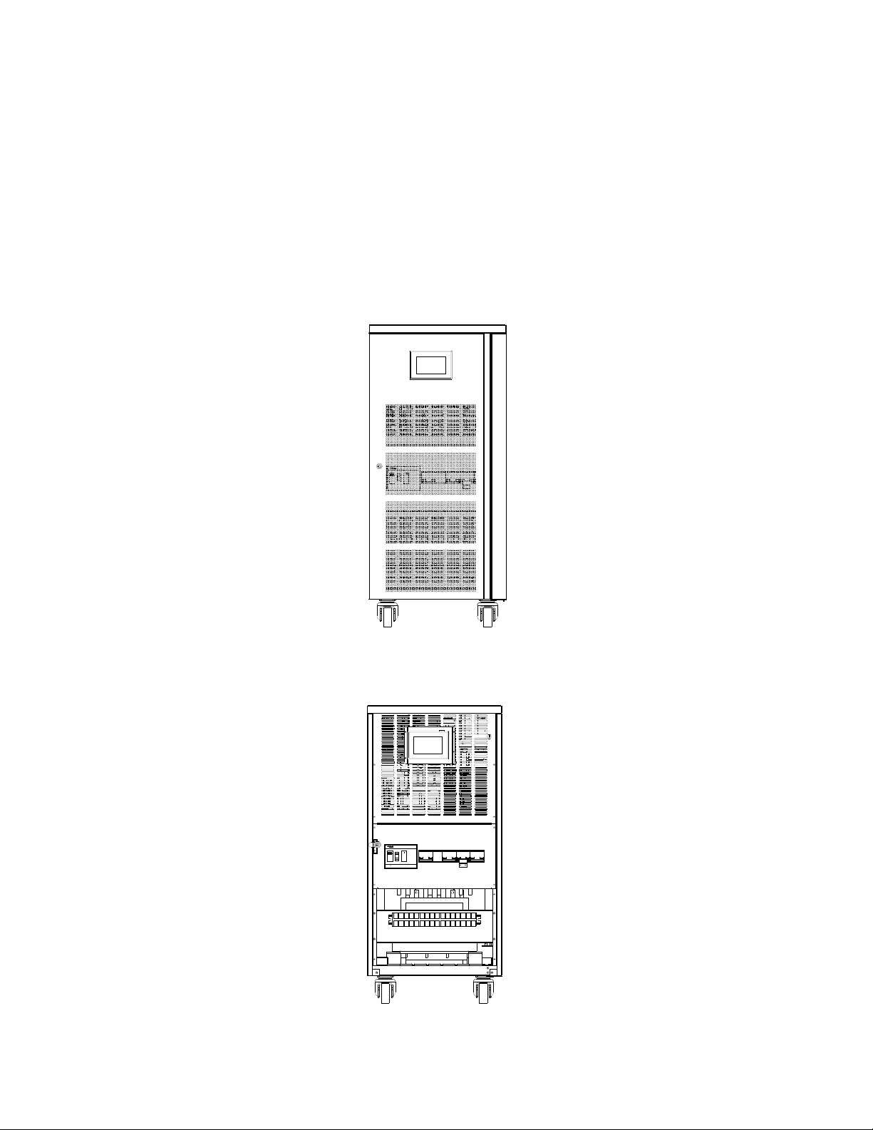
Front view
Figure 1-3 10-30kVA
The Front door map
Figure 1-4 10-30kVA

3
Figure 1-5 Left view of 10-30kVA
Figure 1-6 Right view of 10-30kVA

4
1.5 Specification
Technical parameters
Index 10K 20K 30K
Rated capacity 10kVA 20kVA 30kVA
Rated output power 10kW 20kW 30kW
Solar Input
MPPT Working Voltage and
Range
Actual battery voltage ~ DC480V(375V PV input voltage is
recommended)
Rated Power 10kw 20kw 30kw
Floating Charge Voltage DC275V
Boost charge Voltage 290V
Boost charge time 0.5-4 hours settable(1 hour default)
Over Charge Protection
Voltage DC300V
Battery Input
Rated input voltage 240V
Rated input current 46A 93A 134A
Turn on voltage range 224V~ 290V
DC protection Fuse
Battery reverse protection Support
AC Output
Rated output voltage and
frequency 380VAC,50Hz
Output wiring 3Ф + N + E(Protective earth)
Wave Sine wave
Rated output current 15A 30A 45A
Output voltage precision 380V ±2%
Output frequency precision 50Hz±0.2%
Voltage distortion ≤3% (Linear load)
Output power factor 1
Overload 125%,30 Seconds
Transient response ≤9% R load 0%~ 100%~ 0%
≤6% R load 20%~ 100%~ 20%
Transient recovery ≤60ms voltage recovery to 90% Full RCD load
Efficiency --
Voltage range 200/208/220/230/240VAC (Output power reduces to 90% 208/200V)
Voltage regulation ±2 %
Crest ration 3:1 (maximum)
Protection Short protection Cut off output within 4cycles
Others Low /over voltage、output overload
Environment
Working temperature 0℃~40℃
Altitude <1000m
Noise ≤70dB
Storage temperature -15℃~45℃
Work humidity 20% ~ 95%
EMI/EMS
Conducted IEC62040-02 Class C3
Radiated Class C3
ESD IEC61000-4-2 Level4
RS IEC61000-4-3 Level3
EFT IEC61000-4-4 Level4
Surge IEC61000-4-5 Level4
Safety Safety IEC62040-1
Transportation Drop test --
Vibration test B-WR1-129
Table 1-1

5
Chapter Ⅱ Installation
2.1 Environmental requirements
■ Operating Temperature: 0~40℃
■ Storage temperature: -15℃~45℃
■ Relative Humidity: 20%~95%
■ Cooling Mode: Forced air cooling
■ Altitude: <1000m
■ Verticality: No vibration and the slope should be less than 5°
■ Pollution Level: Grade Ⅱ
Inverter systems should be installed in the clean, cool and ventilated environment. Environment of 20-25℃
operating temperature and 50% Humidity is recommended.
◆◆ NOTE
1. Combustible, explosive or corrosive articles are not allowed to be placed near the Inverter. Inverter will be
damaged in the environment full of metal conductive dust.
2. If Inverter is used at an altitude of 1000m above, output power should be decreased according the following table:
Altitude (m) 1000 1500 2000 2500 3000 3500 4000 4500 5000
Maximum load 100% 95% 91% 86% 82% 78% 74% 70% 67%
2.2 Unpacking
Do not remove the packages before transporting the equipment to the installation site to prevent unexpected
damage. Check the attachment according to the packing list.
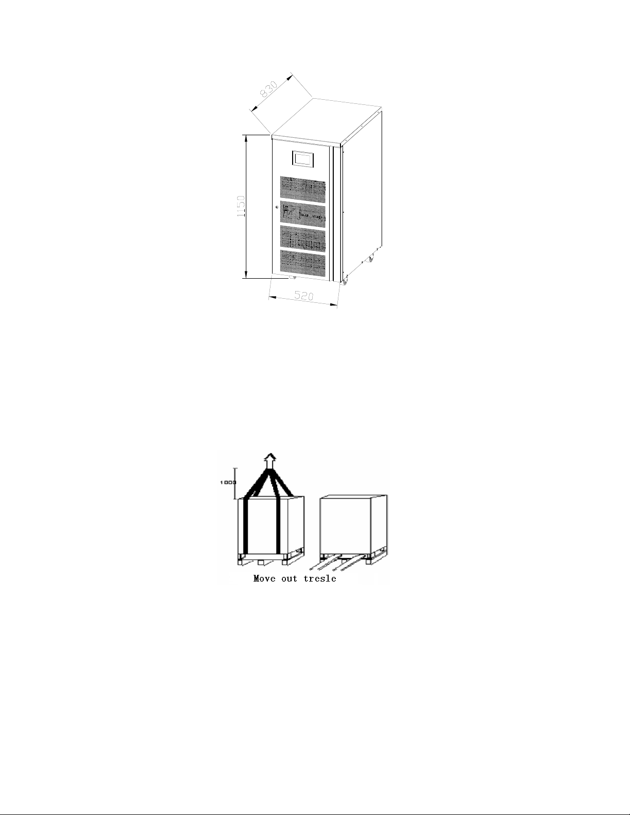
2.3 Mechanical size
The equipments should be fixed in appropriate ways for reliable operation according to the site conditions.
Table 2-1 lists the mechanical parameters of the Inverter power.
Table 2-1
Model Length (mm) Width (mm) Height (mm) Rear panel heat dissipation
clearance (mm)
Weight
(kg)
10kVA
830 520 1150 500
--
20kVA --
30kVA --
Inverter power supply Dimensions (Unit: mm) Figure 2-1.
6
Figure 2-1 inverter power supply dimensions
2.4 Transport
Lifting Transport
【Preparation】Two at least 3 meters long, bearing at least 1.5 tons of the cables.
【Transportation】The Inverter power supply cabinet should transport to the installation site before removing the
packages, Lifting the two suspension ropes from the bottom.
Figure 2-2 Illustration of lifting
7
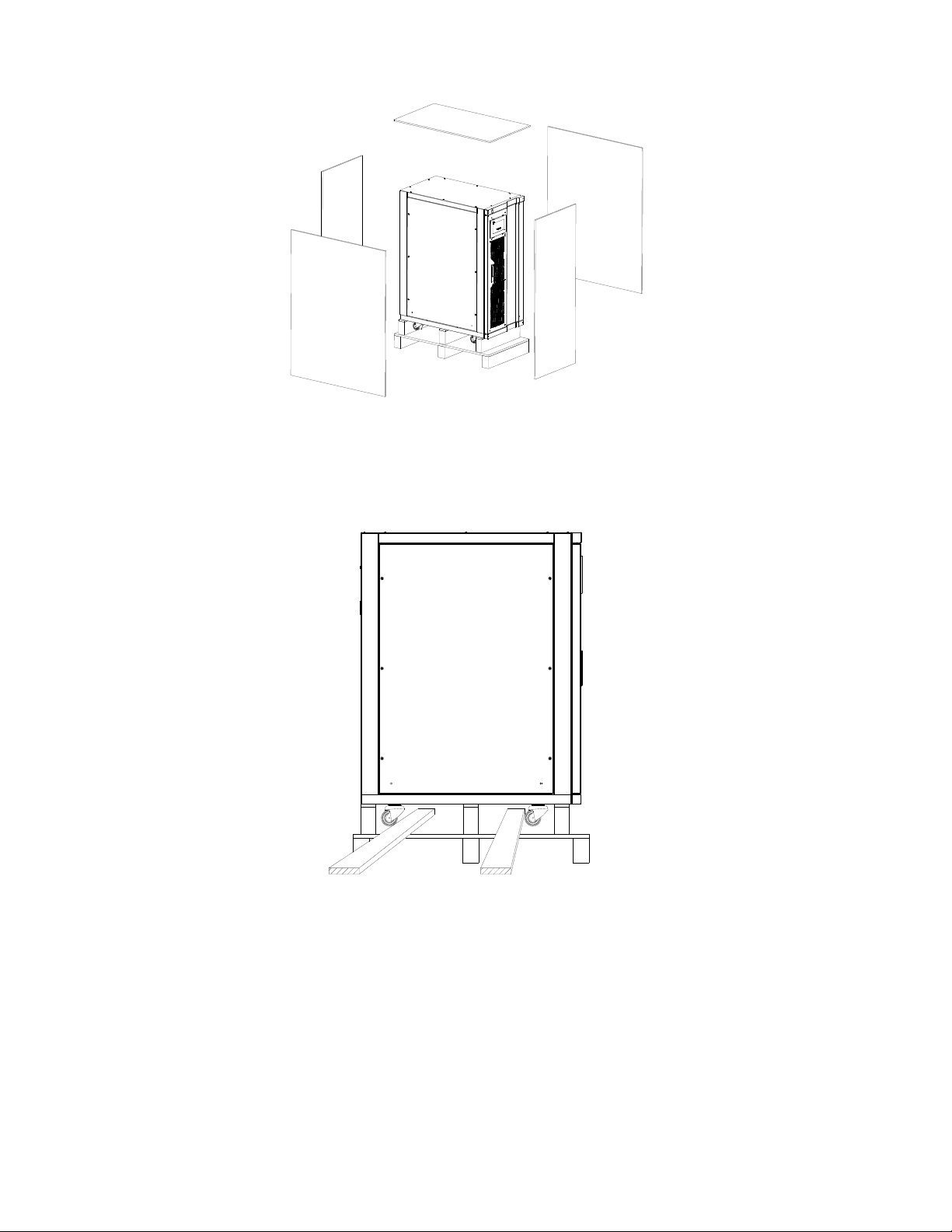
Figure 2-3 Unpacking
Forklift Transport
The equipment could be transported by forklift too. Beware that the Inverter is heavy and take care.
Figure 2-4 Truck crossed the side
2.5 Method of fix
Inverter passes its weight to the ground through four wheels. Use some auxiliary equipment to increase the contact
area if the floor cannot withstand such pressure.
◆◆ NOTE
The cooling air comes from the bottom of the Inverter, so at least 10 cm space should be kept between the bottom
of the Inverter and the floor.
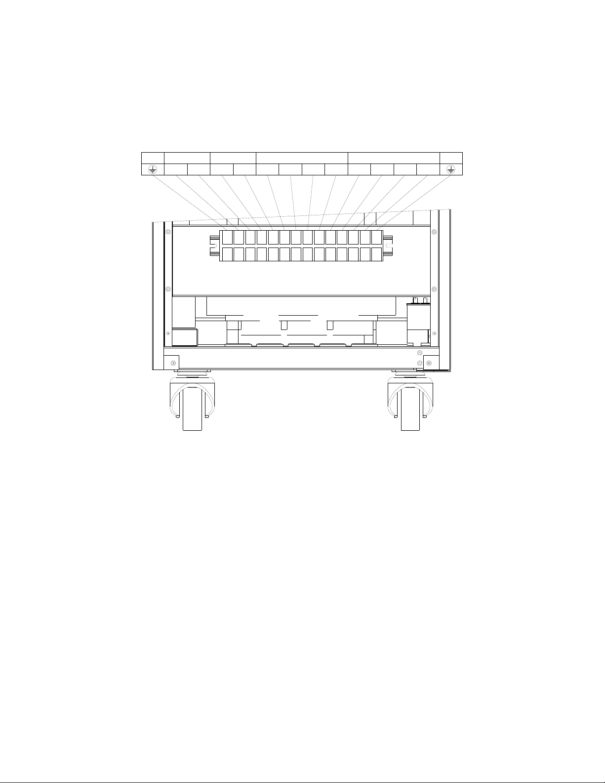
2.6 Terminal block connect

8
Terminal block of the Inverter locates at the front panel with a cover plate for protection. The indications of wiring
are listed in Figure 2-5.
SR NT
PE
PE BATTERY
+-
SOLAR
+-
BYPASS INPUT
TNRS
OUTPUT
Figure 2-5 Terminal block of 10-30kVA

9
Chapter Ⅲ Wiring
3.1 Cable diameter choosing
3.1.1 Current carrying capacity of cable
Table 3-1 shows the relation between cross-section area and current for safe operation.
Current (A)
sectional area (mm2)
Cross-section area (mm2)
1 1.5 2.5 4 6 10 16 25 35 50 70
25℃ rubber 21 27 35 45 58 85 110 145 180 230 285
plastic 19 24 32 42 55 75 105 138 170 215 265
35℃ rubber 20 25 33 42 54 80 103 136 168 215 267
plastic 18 22 30 39 51 70 96 129 159 201 248
3-1 Wire sectional area - current
3.1.2 Selection of power cables
Wires for mains input, bypass input, output, PE and battery need to be power cables. BVR or RV-type soft cables
of AC450V/750V, 70℃ are recommended.
How to determine the current?
The first method is calculating, relative parameters are listed below:
Total efficiency of: 0.9
Output phase voltage:220V
Lowest battery voltage: 240V
Battery current = (Load (watt) / 240
Solar current = (Rated power/ 300 )
Output current = (Load (VA) output value / 220 /3)
If you are not sure about the power of your load, refer table 3-2 cable diameter choosing.
Cable selection
Recommended current density range of power cable is 3 ~ 5A/mm2. The maximum voltage drop on the cable
should be less than 3V to avoid overheat.
Cross-section area of neutral line should be 1.5~1.7 times as the one of phase line. PE (protective earth) line should
be same as one of phase line and minimum value is 10mm2.
10k current and cable sectional area are listed in Table 3-2.
Current/Cable 10kVA 20kVA 30kVA
Current (A) Cable (mm2) Current (A) Cable (mm2) Current (A) Cable (mm2)
Battery 46 6 93 16 134 25
Bypass 15 4 30 4 45 6
Output 15 4 30 4 45 6
Solar 37 6 74 10 108 16
Table 3-2 Rated current and recommended cable cross-section area
◆◆Caution
Voltage of the battery breaker should meet the following requirements for reliable operation: ≥300VDC
3.1.3 Signal wire
Signal wire should be shielded multi-conductor cable.
10
3.2 Cable connection
3.2.1 Power Cable
Mains input and bypass input shares the same input in our factory to support single AC input. Figure 3-1, indicates
that the customer does not have to connect bypass.
If customer wants to operate the Inverter with dual AC input, remove the power cable between mains input and
bypass first in the terminal block, then connect mains input and bypass input independently.
SR NT
PE
PE BATTERY
+-
SOLAR
+-
BYPASS INPUT
TNRS
OUTPUT
Figure 3-1
◆◆Caution
1. All switches should be in the "OFF" state before wiring.
2. Install the recovery plate of the block terminal for good ventilation.
3. PE should be connected because of big leakage current for safety. The resistance between cabinet and Earth
should be less than 1Ω.
3.2.2 Signal Cable
Communication interfaces locate at the top rear panel, including RS232, Modbus, RS485 and dry contact.

11
Figure 3-2 10kVA Inverter Schematic diagram of the interface
1.Modbus card 2. RS232
Note: RS232 and SNMP cannot be used at the same time.
RS232 connection
RS232 communication line is included in the attachment. Connect it between Inverter and supervision terminal.
The definition of each pin is shown in Figure 3-6.
Figure 3-3 RS232 ports
Pin2: Inverter receiving Pin 3: Inverter sending Pin 5: GND Other pin: Do not connect.
SNMP card connection (Option )
Please refer to SNMP guideline for further information.
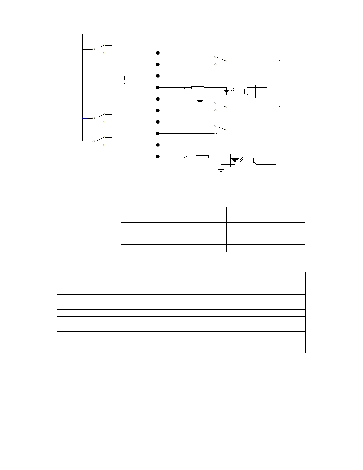
Dry Contact Interface (Option )
Definition of dry contact interface is shown in figure.
12
ALARM
REMOTE SHUTDOWN
1
2
3
4
5
6
8
10
7
9
BYP A SS ON
UPS ON
GND
GND
UPS FAULT
INPUT MAINS FAULT
LOW BATTERY
GND
COMMON
REMOTE START
1.6K
1.6k
This interface provides only a circuit of “On” state (Low impedance) and “Off” state (High impedance), so external
power supply may need for appropriate operation. Voltage of external power supply is 12V.
The following table shows the absolute parameters of critical components of the interface.
Parameter SYMBOL MAX UNIT
DIODE
Reverse Voltage VR 6 V
Forward Current IF 80 mA
Peak Forward Current IF (peak) 1 A
Relay contact DC Volta
g
e VDC 24 V
DC Current IDC 3.0 A
Pin Definition:
Pin Specifications Input and output
1 FAULT Output
2 ALARM Output
3 GND Input
4 REMOTE SHUTDOWN Input
5 COMMON Output
6 BYPASS ON Output
7 LOW BATTERY Output
8 INVERTER ON Output
9 MAINS INPUT ABNORMAL Output
10 REMOTE ON Input
◆◆Note
1. Pin4 and Pin10 are used for remote control. When Pin4 or Pin10 receives a high pulse of 3-10s, inverter will be
shutdown or turned on (Signal less than 3s or longer than 10s is invalid).
2. When inverter is in line mode, function of remote shutdown is not available.
13
Function Description:
Phenomenon Description Reason
PIN1、PIN5 shorted FAULT Inverter internal fault
PIN2、PIN5 shorted ALARM
1.Battery mode
2.Low battery
3.Inverter internal fault or alarm
PIN3 GND OF INPUT
PIN4 REMOTE SHUTDOWN External input signal, high active, remote shutdown
PIN5 COMMON OF OUTPUT
PIN6、PIN5 shorted BYPASS ON Inverter in bypass mode
PIN7、PIN5 shorted LOW BATTERY Battery voltage Low
PIN8、PIN5 shorted INVERTER ON Inverter Works in the line mode or battery mode
(inverter works)
PIN9、PIN5 shorted MAINS INPUT FAULT Mains AC abnormal
PIN10 REMOTE ON External input signal, high active, turn on inverter
remotely.
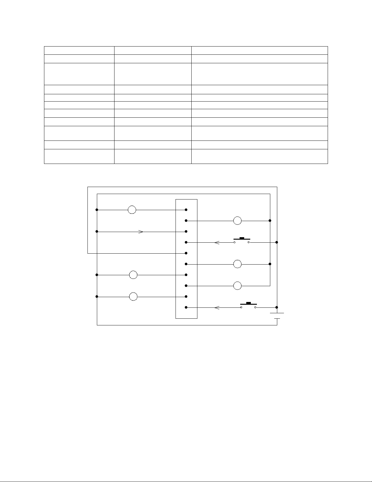
Application demonstration
1
2
3
4
5
6
7
8
9
10
FAIL
ALARM
GND
REMOTE
COMMON
BYPASS ON
BATTERY LOW
INVERTER ON
UTILITY FAILURE
REMOTE ON
SHUTDOWN
12V
A 6-24VDC source is connected between Pin 5 and Pin3. Keys of remote start and remote shutdown are used for
remote control. And the lights are used to indicate the status of Inverter for remote supervision.

14
Chapter Ⅳ Power On and Debugging
4.1 Preparation
4.1.1 Input breaker description
Bypass breaker Q2--- Switch on/off bypass AC, to the bypass STS
Maintenance breaker Q3--- Switch on/off connection between bypass and output
Output breaker Q4--- Switch on/off inverter output
Battery breaker B1—Switch on the battery bank.
Solar breaker P1—Switch on the solar bank.
◆◆ Note
Repair break Q3 is designed for repairing. Only qualified technical personnel are allowed to operate this breaker.
4.1.2 Power on steps
Make sure all the breaks are in “OFF” state before connecting any cables. Check the AC input, battery input
voltage before switching on the breakers. Connect the neutral line if your load is single-phase load.
◆◆ Note
Do not connect any load to the Inverter to prevent unexpected damage!
Inverter power supply system start in the following order:
Step 1:Turn on battery breaker B1 and Solar breaker P1, bypass breaker Q2 and output breaker Q4. The buzzer will
beep and LCD will be lightened. Wait 1 minutes to start the DC/DC . Inverter is working in bypass mode
and battery is charged.
Step 2: Click the "Menu" option to enter the function menu page. Click the "System Control" icon. Select the
"Inverter ON" icon, the main screen shows the inverter is starting. 20s later the inverter will work and the
LCD flow chart shows the energy flow.
◆◆ Note
1. Do not click the LCD screen frequently. Otherwise the screen will be locked.
2. When the LCD screen was locked, unlock the screen according to the indication.
Remarks: In normal situation do not use this function!
4.2 Function test
Mainly check the various working mode of the handover, fault alarm (sound and sound) and LCD screen display
instructions and other functions.
4.2.1 LCD display and control panel
A detailed Icon description of the series on a single Inverter power steps in Figure 4-1. The process of checking the
various indicator lights blinking, LCD touch screen keys.

15
Figure 4-1 Display Control Panel
Analog fault condition (closing the input mains) to make an alarm, Check the "sound and light alarm" function,
select "Menu" to enter to check the real-time display of inverter information.
16
Chapter Ⅴ LCD panel operation
5.1 LCD panel
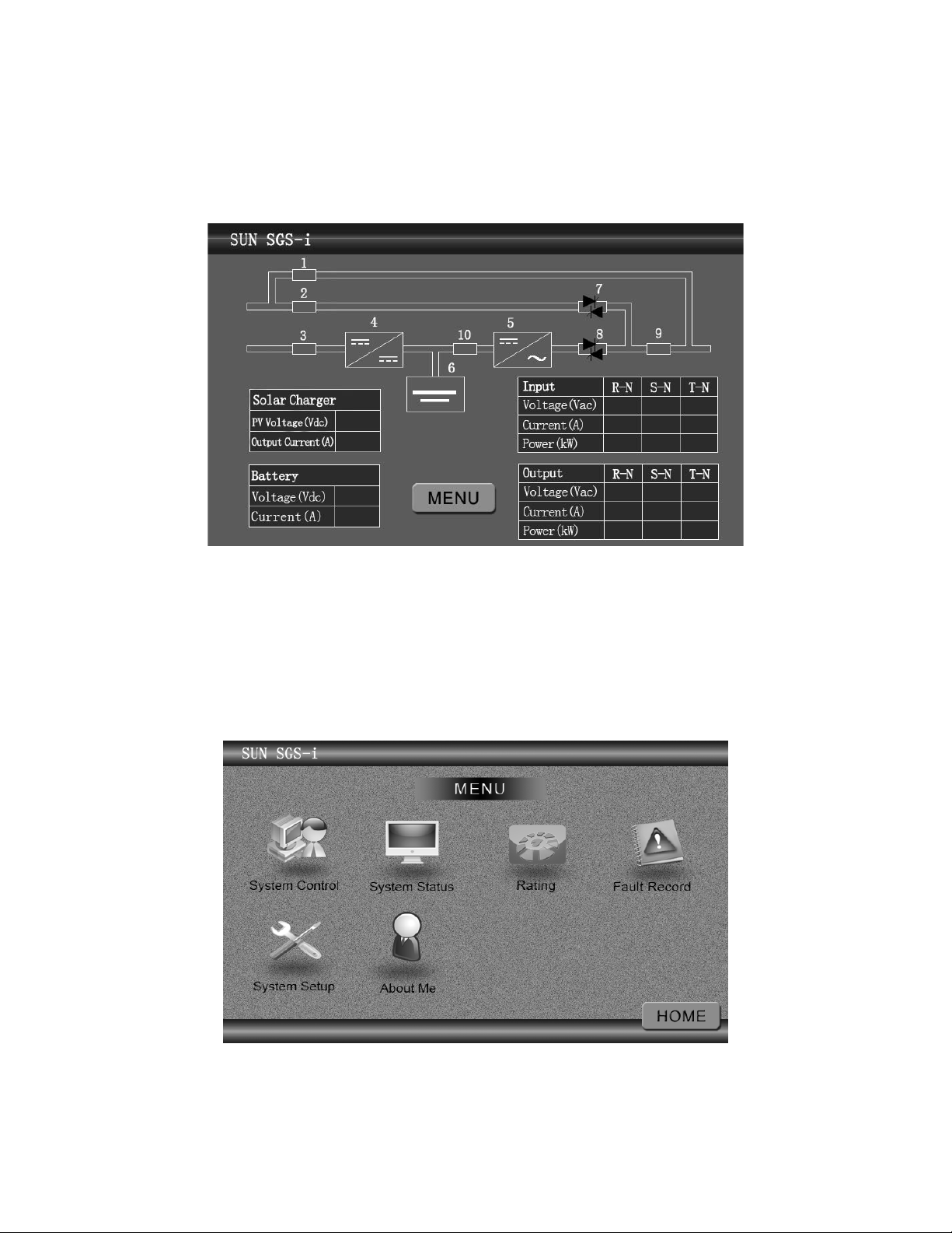
5.1.1 Description
Description of LCD panel is shown in Figure 5-1.
1. Maintenance bypass breaker status 2. Bypass breaker status
3. PV input breaker status 4. PV charger status
5. Inverter Status 6. Battery status
7. Bypass Static Switch 8. Inverter static switch
9. Output breaker status 10.Battery breaker status
Figure 5-1 LCD Panel
Press the "Menu" key to enter the function menu page. Menu panel consists of six functional areas (Figure 5-1-1-1):
System control, System state, Rating, Fault Record, System Setup, About me.
Figure 5-1-1-1 LCD panel function area
17
5.1.2 HOME page description
Some common inverter work situation will be described blow.
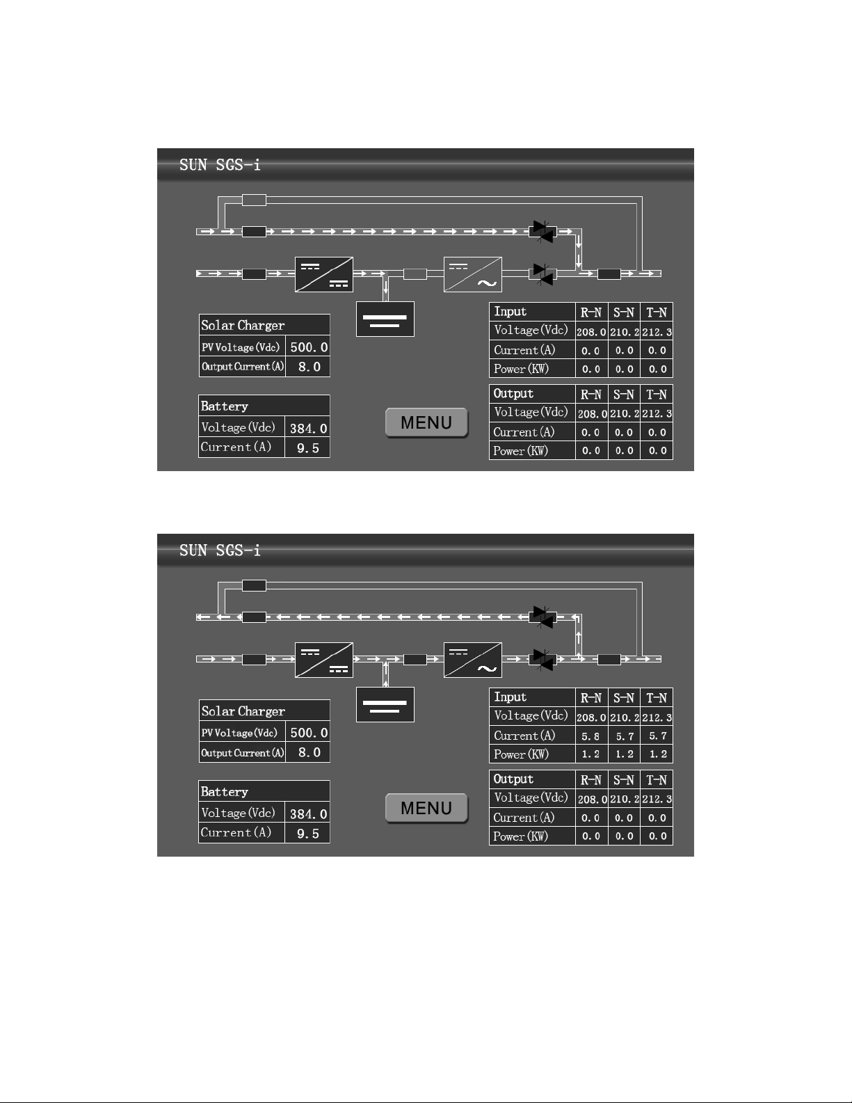
【Bypass mode】: Bypass mode flow figure as show in Figure 5-1-1-2.
Figure 5-1-1-2 Bypass mode flow figure
【On grid mode】: On grid mode flow figure as show in Figure 5-1-1-3
Figure 5-1-1-3 On grid mode flow figure
The flow figure of other work mode will not describe here.
5.1.3 MENU page description
Function key area contains six keys (Figure 5-2):
【System Control】: Inverter On/Off control (Figure 5-3).
【System state】: Check the input, output and other real-time status information.
【Rating】: Display Inverter machine model, rated capacity, rated input, rated output and battery voltage and other
Table of contents
Other PSC Solar Inverter manuals


Popular Inverter manuals by other brands


Delta
Delta M Series Operation and installation manual

Centech
Centech 60601 Owner's manual & safety instructions

Tripp Lite
Tripp Lite PowerVerter RV3012OEM Specifications

Delta
Delta M50A-260 Installation and operation manual

Delta
Delta RPI-H3 Operation and installation manual

Delta
Delta RPI-H3 owner's manual