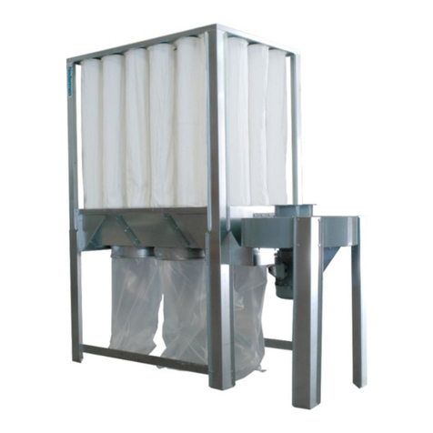
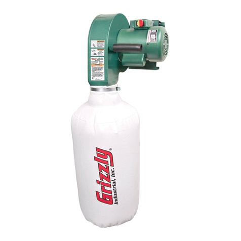
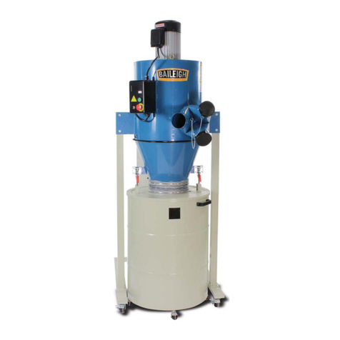
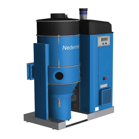
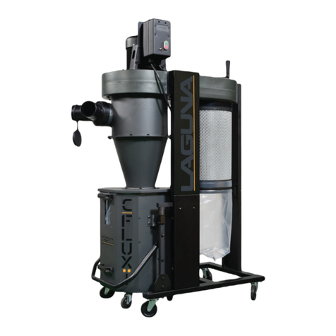
PSI Woodworking Products TEMPEST TEMP2PCX User manual

TEMP2PCX
2HP PORTABLE CYCLONE
DUST COLLECTOR.
VERSION 1 • 3/10

Thank you for purchasing one of PSI’s growing family of woodworking products. This Portable
TEMPEST™ cyclone system is engineered and manufactured to the highest standards of quality.You will
find this unit to be a remarkable dust collection machine in your shop.
Warranty
This product is warranted against defects in material and workmanship for a period of five years on the
motor and all other components. This warranty applies to the original purchaser of the product and is lim-
ited to the repair or replacement of the product or its parts at the discretion of PSI Woodworking Prod-
ucts. Excluded are parts which have been misused, abused, altered, or consumed by normal operation of
the machine. This TEMPEST™ is warranted for the collection of wood dust only.
Also excluded are direct or consequential damages to persons, properties or materials.Your invoice serves
as proof of purchase and must be referenced to authorize any warranty repair. Call your dealer for proper
authorization. As the owner, you are responsible for returning warranty service parts at your expense. Any
defective part(s) will be repaired or replaced at the manufacturer’s discretion.
Safety
• Do not use this system near flammable or combustible liquids or gases including gasoline or other fuels,
cleaners, oil-based paints, natural gas or explosive dusts such as coal dust, magnesium, grain dust
or gun powder.
• Do not vacuum anything that is burning or smoking such as cigarettes or hot ashes.
• Do not vacuum toxic materials or use near hazardous materials.
• Do not use outdoors or on wet surfaces.
• Do not operate with a full waste container.
• To avoid collapse of ducting, it is recommended to use twenty-six gauge steel or thicker. Twenty-four
gauge metal or thicker is the prefered. gauge.
• It is best to install on a stable, level surface. When being assembled on a stand, make sure that the base
and supporting structure is stable and the casters are locked.
• Do not use without canister and dust bin attached.
• Turn off controls before unplugging the unit.Do not pull cord to unplug; grasp plug and remove
from receptacle.
• Do not operate with the motor/blower off of the cyclone as this could cause severe overheating and/or
motor burnout.
• Do not use with damaged cord, plug, or other any part. Plug in power supply in to a properly grounded
outlet and appropriate breaker on your fuse box.
• Do not wear loose clothing in the area of any inlets because high suction could pull and stretch
garments into blower.
• If your ductwork consists of plastic hose or pipe, ground hose or pipe by wrapping bare copper wire
around the exterior surface and ground the wire at either end.
• Keep hands free from spinning impeller.

Features
• Powerful motor blower unit has a proven flawless performance record
• 1/2- micron filter cartridge for fine filtration
• Captures over 99% of the dust and debris before it passes through the motor blower
• Includes dolly with locking casters and 35 gallon fiber drum
• Easy cleaning of debris from the collection canister
• With nearly clean filters, system consistently runs at peak performance
• Aluminum impeller providing superior performance
• “Neutral vane” intake maximizes airflow
• Longer cyclone funnel improves separation efficiency
• Includes convenient heavy-duty on/off switch on power cord
• Only 85” high — fits through most doorways
• Includes built-in re-circulation system — no need for filter cleanout container
Contents
Box #1 – Motor Blower and Housing
Box #2 – Cyclone Cone
Box #3 – Stand with Base
Box #4 – Fiber Drum with Recirculating Kit
Box #5 – Filter Cartridge
Specifications
Motor 2.0 HP, 9 Amps
3450 RPM
Impeller 14” Aluminum
Max. Air Flow 1025 CFM
(through cyclone)
Filter Cartridge 36” x 14” OD
350 sq. ft. filter area
Filter Cleanout Drum
N/A - unit uses re-circulating cleanout
Debris Drum 35 gallon
Height (on drum) 85”
Weight 200 lbs.
Sound Rating 76db
Air Inlet Diameter 6”
Dust outlet to Filter 6”
Footprint 27-1/2” x 21-1/4”
(stand base)

ASSEMBLY
To begin assembly of your TEMP2CX you will need a pair of pliers, an adjustable wrench, a Phillips head
screwdriver, a jig saw or snips, a drill with a HSS 1/8” bit and a couple of friends to assist. Lay out all of the
components out to assure you know how parts connect as well as an account for all of the parts.
The Stand Assembly — Refer to Parts Diagram on page 9
A. Place two M12 nuts (2) on to the casters (1) pass its post through the bottom of the base (5) and
through the bottom of the vertical support posts (6 & 7). Attach vertical supports (6 & 7) to the base with
a 12mm washer (3), follow with 12mm lock washer (4) and then M12 nut (2) at the lip starting at the
#1 on the base. Continue to attach supports in numerical order as shown in Diagram 1. The longer verti-
cal supports (6) go to the back side of the base. Do not tighten completely, give some tension but give
enough where support can turn, if needed. Continue to do all four and that all “L”-shaped lips are facing
inside, then tighten. See Diagram 1.
B. After the vertical supports are in place, attach the mid horizontal support braces (8 & 9) using M8 x 20
carriage bolts (18) through followed by 8mm washer (14), follow with 8mm lock washer (17) and then
M8 nut (15). Again, these braces are attached to the vertical supports. Once all the braces are attached,
tighten to vertical supports. The mid horizontal supports are attached to form a 90° angle to the vertical
support. See Diagram 2.
Labeled as #1
Labeled as #4
Labeled as #3
Labeled as #2
NOTE: Match numbered supports
to numbered holes on base/
90°
Diagram #1
Diagram #2

10
9
98
8
77
6
5
1
1
6
10
11 18
13
13
12
12
10
Diagram #3 – Stand Assembly
C. Next, then attach the upper horizontal supports (10) using M8 x 20 carriage bolts (18) through
followed by 8mm washer (14), follow with 8mm lock washer (17), then M8 nut (15). One support is for
front; two are used for the back. The third upper support brace is attached at the highest holes of the long
vertical supports (6). The two back upper supports (10) are used accommodate filter brackets (11 & 16).
D. Attach the filter brackets (11 & 16) using M8 x 20 carriage bolts (18) through followed by 8mm wash-
er (14), lock washer (17) and M8 nut (15). Next, attach the bracket arms (13) to the filter brackets with
M8 x 20 carriage bolts (18) through by 8mm washer (14), 8mm lock washer (17) and M8 nut (15). You
need to mount the filter support rods (12). NOTE: one support rod is at the furthest hole and one
support rod in middle of arm. See Diagram 3. Before attaching filter support rods (12) place one M8 nut
(15) before inserting to the bracket arms (13). Once rod is in place then follow with 8mm washer (14),
8mm lock washer (17) and add M8 nut (18) but do not tighten until filter cartridge (51) is in place.

The Cyclone
E. After the stand is assembled, attach the starter switch (22). The switch support plate (19) is placed on
the front left side of the stand on the horizontal support (10). The switch plate is attached with one M8 x
20 carriage bolt (18) through the horizontal support and followed by 8mm washer (14), lock washer (17)
and M8 nut (15). The starter switch (22) is attached with two 5mm x 16 screws (21) and two 5mm wash-
ers (20) to the support plate (19). See Diagram 4.
F. Now you are ready to attach your cyclone to the stand. Place the cyclone cone (44) to the center of
your assembled stand, and align the holes up with those in the horizontal supports (10). Once the cone
is in place go around the inside diameter of cone with foam stripping (40). See Diagram #5. Lay a bead of
caulk over the foam.
19
10
22
Diagram #4

Diagram #6
G. Now, with the assistance of one or two friends, bring the cyclone motor housing assembly (25, 26, 27,
28 and 39 — note that everything is assembled as a single piece) and align with cyclone cone (44) so that
the holes align. See Diagram 6. Once everything is aligned and caulked into place; using six M8 x 20 car-
riage bolt (18) [facing downward] through the two pieces, the cyclone cone and motor housing, followed
by 8mm washer (14), lock washer (17) and M8 nut (15). Tighten with adjustable wrench. And then, use
four M8 x 20 carriage bolt (18) [facing downward] through the horizontal support (10) of the stand and
followed by 8mm washer (14), lock washer (17) and M8 nut (15).
H. Mark the center of the fiber drum (43) with an “X” by creating two cross sectional lines with a wax
pencil. Align the flange (44) and the cross sectional lines and trace out the center of the flange onto the
can’s lid as a guide for mounting the flange. With 1/8” sheet metal screws attach and caulk (to create
an airtight seal) the flange to the lid. Reattach the lid. Now place the fiber drum (43) under the cyclone
cone’s center and attach 7” hose (46) to each side using the two 7” hose clamps (45).
Filter Cartridge Assembly
I. Attach the 6” bell connector (50) to either end of the filter cartridge. Place a bead of silicone around
the rim of the bell connector and place on to one of ends of the filter canister. Let cure. Then, fasten four
sheet metal screws for extra support. On the other end attach the funnel reducer (52) with silicone; this
is the bottom of the completed assembly, and after curing repeat with four sheet metal screws as you did
on the bell connector. Next, adhere with silicon the 4” blast gate (53) to the funnel reducer. end Attach
the filter to the stand by using the rear brackets and rods. Using two sheet metal screws with a washer go
through the bracket arm’s holes and directly mount the filter canister. Attach the 6” hose (30) to bell con-
nector (top) with a 6” band clamp (29) to the 6” exit port on the cyclone and the other 6” band clamp.
J. At the intake port add the 6” band connector (41) to join inlet “T” (42). The 4” hose (49) is the attached
to the “T” and leads to the 4” port on the bottom of the filter canister with the 4” hose clamps (54). This
acts as a built-in recirculation system and all of the dust goes into your fiber drum. See Diagram 7.

K. Use silicone sealer, duct tape or a metal sealing tape to seal all the connections for better air flow and
performance.
NOTE: This cyclone dust collector uses either 6” hose that can be reduced to most woodworking ma-
chine port sizes as you move it to the machine you are using or can be a stationary unit where 6” duct-
work can lead to the machine in use. It is recommended that you check your fiber drum after each use to
check dust levels or purchase a PSI #BINSENSOR to let you know when it time to empty the fiber drum.
4I
42
54
49
54
53
12
51
30
Diagram #7

Using the Cyclone
1. Roll the cyclone to the proximity of your machine.
2. Connect the 6” hose to your machine port – adapt down to 4”, if necessary, with an appropriate
6” to 4” adapter.
3. Close the 4” recirculation blast gate to the bottom of the filter.
4. Open the blast gate to your machine and turn on the cyclone – never turn on the cyclone with all of
your gates closed.
5. Dust will collect in the fiber drum. Check dust level periodically to make sure it is not more than half
full. Empty the drum when more than half full. Note: a drum that is too full will result in debris
continuing to clog up the canister.
6. Clean the filter cartridge periodically by using compressed air (or a shop vac in reverse) to blow any
dust off the internal pleats of the filter media.
7. Using the recirculation system:
• Close the gates to the cyclone main intake.
• Open the gate under the funnel reducer. Turn on the cyclone while blowing the filter cartridge
with air. The ambient dust from the filter will settle in the collection drum.
• Close the blast gate under the filter before using the cyclone for normal dust collection..
COMPONENTS
NO DESCRIPTION QTY
1 CASTER 4
2 M12 NUT 12
3 12mm WASHER 4
4 12mm LOCK WASHER 4
5 BASE PLATE 1
6 LONG VERTICAL SUPPORT 2
7 SHORT VERTICAL SUPPORT 2
8 MID HORIZONTAL SUPPORTS
(FRONT & BACK) 2
9 MID HORIZONTAL SUPPORTS
(LEFT & RIGHT) 2
10 TOP HORIZONTAL SUPPORTS
(MAIN CYCLONE SUPPORT) 3
11 LEFT BRACKET 1
12 CANISTER HOOK 2
13 BRACKET ARM 2
14 8mm WASHER 43
15 M8 NUT 43
16 RIGHT BRACKET 1
17 8mm LOCK WASHER 39
18 M8X20 CARRIAGE BOLT 39
19 SWITCH SUPPORT 1
20 5mm WASHER 2
21 M5X16mm PHILLIP SCREW 2
22 SWITCH WITH FACE PLATE 1
22a SWITCH BOX 1
47 M3X16 PHILLIP SCREW 2
48 POWER CORD 1
NO DESCRIPTION QTY
14 8mm WASHER 4
15 M8 NUT 4
17 8mm LOCK WASHER 4
18 M8X20 CARRIAGE BOLT 4
25 MOTOR 1
25a MOTOR FAN 1
25b MOTOR COVER 1
25c CAPICITOR 1
25d MOTOR ELECTRICAL BOX 1
25e TERMINAL WIRE CONNECTOR
25f START/STOP SWITCHES 2
26 KEY 1
27 MOTOR MOUNTING PLATE 1
28 BLOWER 1
29 6” HOSE CLAMP 2
30 6” HOSE 1
31 IMPELLER 1
32 FOAM GASKET 1
33 24mm WASHER 1
34 24mm LOCK WASHER 1
35 M24 NUT 1
36 6mm WASHER 12
37 6mm LOCK WASHER 12
38 M6X20 HEX SCREW 12
39 CYCLONE BODY 1
40 FOAM GASKET 1
41 6” BAND CLAMP 1
42 664 “T” LATERAL 1
43 35 GAL. FIBER DRUM 1
44 CYCLONE CONE 1
44A 7” FLANGE 1
45 7” HOSE CLAMP 2
46 7” HOSE 1
48 POWER CORD 1
49 4” HOSE 1
50 6” BELL CONNECTOR 1
51 FILTER CANISTER 1
52 FUNNEL REDUCER 1
53 4” BLAST GATE 1
54 4” HOSE CLAMP 3
55 TEMPEST LABELS 2
Stand Components Cyclone Components
Phillips
Head Screw
Carriage
Bolt
Flange
Bolt
Flat Washer Lock Washer Hex Nut

22
21
20 19
10
9
9
8
8
7
2
4
3
7
66
5
1
2
10
10
15
15
15
13
12
12
17 14
18
16
18
48
18
11
14
47
14

2 5
2 5a
2 5b
2 6
2 7
2 8
2 9
3 0
3 1
5 0
5 1
5 2
5 3
5 4
3 2
3 3
3 4
3 5
3 6
3 7
3 8
4 0
4 4
4 6
1 5
1 5
1 7 1 7
1 4
4 9
5 4
1 4
1 8
4 1
4 2
1 8
3 9
4 7
3 1
4 5
4 5
4 4
4 3
Pre-Assembled
Motor Assembly

VERSION 1 • 3/10
Table of contents
