Psion PowerScan D8330 User manual

PowerScan™
D8330/M8300
USER MANUAL
September 23, 2011
PN 8000166.B
ISO 9001 Certified
Quality Management System

© Copyright 2011 by Psion Inc.
2100 Meadowvale Boulevard
Mississauga, Ontario, Canada L5N 7J9
http://www.psion.com
This document and the information it contains is the property of
Psion Inc. This document is not to be used, reproduced or copied, in
whole or in part, except for the sole purpose of assisting in proper
use of Psion manufactured goods and services by their rightful own-
ers and users. Any other use of this document is prohibited.
Disclaimer
Every effort has been made to make this material complete, accurate,
and up-to-date. In addition, changes are periodically incorporated
into new editions of the publication.
Psion Inc. reserves the right to make improvements and/or changes
in the product(s) and/or the program(s) described in this document
without notice, and shall not be responsible for any damages includ-
ing, but not limited to, consequential damages, caused by reliance on
the material presented.
Psion, the Psion logo and the names of other products and services
provided by Psion are trademarks of Psion Inc.
Windows®and the Windows Logo are trademarks or registered
trademarks of Microsoft Corporation in the United States and/or
other countries.
All trademarks used herein are the property of their respective owners.

Return to Factory Warranty
Psion provides a return to factory warranty on this product for a
period of twelve (12) months in accordance with the statement of
Warranty and Product Support provided at:
http://www.psion.com/warranty
The warranty on Psion manufactured equipment does not extend to
any product that has been tampered with, altered, or repaired by any
person other than an employee of an authorized Psion service orga-
nization. See Psion terms and conditions of sale for full details.
Important: Psion warranties take effect on the date of shipment.
Updates And Language Availability
Canada/UK/US
The latest drivers and documentation updates for this product are
available on the Internet. Log on to: www.psion.com
I
Su Internet sono disponibili le versioni aggiornate di driver e docu-
mentazione di questo prodotto. Questo manuale è disponibile anche
nella versione italiana. Collegarsi a: www.psion.com
F
Les versions mises à jour de drivers et documentation de ce produit
sont disponibles sur Internet. Ce manuel est aussi disponible en ver-
sion française. Cliquez sur: www.psion.com
D
Im Internet finden Sie die aktuellsten Versionen der Treiber und
Dokumentation für dieses Produkt. Die deutschsprachige Version die-
ses Handbuches ist auch verfügbar. Adresse:
www.psion.com
E
En Internet están disponibles las versiones actualizadas de los driv-
ers y documentación de este producto. También está disponible la
versión en español de este manual. Dirección Internet :
www.psion.com

Waste Electrical and Electronic
Equipment (WEEE) Directive
2002/96/EC & Waste Batteries Directive
2006/66/EC
This Product, and its accessories, comply with the requirements of the
Waste Electrical and Electronic Equipment (WEEE) Directive 2002/96/
EC. The batteries used in this Product comply with the requirements of
Directive 2006/66/EC.
If your end-of-life Psion product, battery or accessory carries a label
as shown here, please contact your local country representative for
details on how to arrange recycling. For a list of international subsid-
iaries, please go to:
http://www.psion.com/environmental-compliance.htm
Restriction on Hazardous Substances (RoHS)
Directive 2002/95/EC
What is RoHS?
The European Union has mandated that high environmental stan-
dards be met in the design and manufacture of electronic and electri-
cal products sold in Europe, to reduce hazardous substances from
entering the environment. The “Restriction on Hazardous Sub-
stances Directive (RoHS)” prescribes the maximum trace levels of
lead, cadmium, mercury, hexavalent chromium, and flame retardants
PBB and PBDE that may be contained in a product. Only products
meeting these high environmental standards may be “placed on the
market” in EU member states after July 1, 2006.
RoHS Logo
Although there is no legal requirement to mark RoHS-compliant
products, Psion Inc. indicates its compliance with the directive as fol-
lows:
The RoHS logo located either on the back of the product or under-
neath the battery in the battery compartment (or on a related acces-
sory such as the charger or docking station) signifies that the
product is RoHS-compliant as per the EU directive. Other than as
noted below, a Psion product that does not have an accompanying
RoHS logo signifies that it was placed on the EU market prior to
July 1, 2006, and is thereby exempt from the directive.
Note: Not all accessories or peripherals will have a RoHS logo due to
physical space limitations or as a result of their exempt status.
Support Services and Worldwide Offices
Psion provides a complete range of product support services to its
customers worldwide. These services include technical support and
product repairs.

Technical Support
For technical support in North America:
Call Toll free: +1 800 387 8898 Option 3, or
Direct Dial: +1 905 813 9900 Ext. 1999 Option 3.
For technical support outside of North America, please follow the link
for your region on the Psion Community Support website at:
http://community.psion.com/support
Product Repairs
For repair service in North America:
Call Toll free: +1 800 387 8898 Option 2, or
Direct Dial: +1 905 813 9900 Ext. 1999 Option 2.
For repair service outside of North America, please
contact your local office listed in the following document:
http://www.psion.com/documents/com/quickReferenceGuides/
Help_Desk_Contact_Numbers_A4.pdf
Worldwide Offices
Company Headquarters
Psion Inc.
2100 Meadowvale Boulevard
Mississauga, Ontario, Canada L5N 7J9
Tel: +1 905 813 9900
Fax: +1 905 812 6300
E-mail: salescdn@psion.com
North American Headquarters & U.S. Service Centre
Psion Corporation
3000 Kustom Drive
Hebron, Kentucky
USA 41048
Tel: +1 859 371 6006
Fax: +1 859 371 6422
E-mail: salesusa@psion.com
International Subsidiaries
www.psion.com/us/about/contact_psion-offices.htm
Psion S.A. Psion Espana S.L.
La Duranne Plaza de la Pau, s/n Edificio 3, 2º
135 Rue Rene Descartes 08940 Cornella de Llobregat,
BP 421000 Barcelona, Spain
13591 Aix-En-Provence
Cedex 3; France
Tel: +33 4 42 90 88 09 +34 902 884 220
Fax: +33 4 42 90 88 88 +34 934 750 230

NOTES

TABLE OF CONTENTS
i
CONTENTS
1 INTRODUCTION................................................................................................... 1
2Installation ..........................................................................................................2
2.1 PowerScan™ D8330 Interface Cable Connections ......................................2
2.2 BC-80X0 Interface Cable Connections ..........................................................4
2.3 RS-232 Connection ...........................................................................................5
2.4 USB.......................................................................................................................5
2.5 IBM USB POS......................................................................................................6
2.6 WEDGE Connection ............................................................................................7
2.7 PEN Emulation Connection...............................................................................7
2.8 Network Connections.........................................................................................8
2.8.1 BC-8060 Network Connectors ........................................................................8
2.8.2 Network Cabling .................................................................................................9
2.8.3 Network Termination ....................................................................................... 10
2.9 PowerScan™M8300 Battery Maintenance................................................... 11
2.9.1 Battery Charging................................................................................................11
2.9.2 Replacing PowerScan™M8300 Batteries ......................................................11
2.10 Mounting The BC-80X0 / C-8000 Cradle ................................................... 12
2.10.1 Desktop Mounting .............................................................................................13
2.10.2 Wall Mounting.................................................................................................... 16
3PowerScan™M8300 System and Network Layouts .................................. 18
3.1 Stand-alone Layouts........................................................................................ 18
3.1.1 Point-to-Point Reader Layout........................................................................ 18
3.1.2 Stand-Alone Layout with Multiple Readers ................................................. 18
3.1.3 Multiple Stand-Alone Layouts ....................................................................... 19
3.1.4 C-BOX Layout .................................................................................................. 20
3.2 Multidrop STAR-System™ Network Layouts .............................................. 21
3.2.1 Host Master Layout......................................................................................... 21
3.2.2 BC-8060 Master Layout ............................................................................... 22
3.2.3 Master BC-8060 Network Troubleshooting............................................... 23
4Configuration.................................................................................................... 24
4.1 Configuration Methods ................................................................................... 24
4.1.1 Reading Configuration Barcodes .................................................................. 24
4.1.2 Using the Original Manufacturer’s Datalogic Aladdin™............................ 24
4.1.3 Copy Command ................................................................................................ 24
4.1.4 Sending Configuration Strings from Host................................................... 25
4.2 Setup Procedures ............................................................................................ 25
4.3 PowerScan™D8330 Setup............................................................................. 26
4.4 PowerScan™M8300/BC-80X0 Point-to-Point Setup.............................. 26
4.5 PowerScan™M8300/BC-80X0 Stand-Alone Setup ................................. 27

POWERSCAN™D8330/M8300
ii
4.5.1 Using Multiple M-Series Readers with the Same Cradle .......................... 29
4.5.2 PowerScan™M8300/STAR-Modem™ in Stand-Alone Mode.................... 30
4.6 PowerScan™M8300/STAR-System™ Setup .............................................. 31
4.7 BC-8060 STAR-System™ Network Setup ................................................. 33
4.8 Interface Selection.......................................................................................... 35
4.9 USB Reader Configuration............................................................................. 38
4.10 Changing Default Settings............................................................................. 40
RS-232 PARAMETERS................................................................................... 41
USB PARAMETERS ........................................................................................ 46
WEDGE PARAMETERS................................................................................... 52
PEN EMULATION ............................................................................................ 58
NETWORK PARAMETERS............................................................................. 63
DATA FORMAT................................................................................................ 68
POWER SAVE .................................................................................................. 80
READING PARAMETERS............................................................................... 82
DECODING PARAMETERS ............................................................................ 88
CODE SELECTION............................................................................................ 91
ADVANCED FORMATTING...........................................................................109
RADIO PARAMETERS ...................................................................................128
DISPLAY and KEYPAD PARAMETERS...................................................... 134
5REFERENCES .................................................................................................138
5.1 RS-232 Parameters ......................................................................................138
5.1.1 Handshaking....................................................................................................138
5.1.2 ACK/NACK Protocol...................................................................................... 139
5.1.3 FIFO ..................................................................................................................140
5.1.4 RX Timeout....................................................................................................... 141
5.2 Pen Parameters...............................................................................................141
5.2.1 Minimum Output Pulse...................................................................................141
5.2.2 Conversion to Code 39 and Code 128 ..........................................................141
5.2.3 Overflow ...........................................................................................................142
5.2.4 Output and Idle Levels...................................................................................142
5.2.5 Inter-Block Delay ...........................................................................................143
5.3 Network Parameters......................................................................................143
5.3.1 Slave Address Range First/Last .................................................................143
5.3.2 Network Warning Message ...........................................................................143
5.3.3 Reception Warning Message.........................................................................144
5.3.4 Master Header/Terminator Selection .........................................................144
5.4 Data Format ....................................................................................................145
5.4.1 Header/Terminator Selection.......................................................................145
5.4.2 Define Special Key Sequence .......................................................................146
5.4.3 Address Stamping..........................................................................................154
5.4.4 Address Delimiter...........................................................................................154
5.4.5 Time Stamping Format..................................................................................154

TABLE OF CONTENTS
iii
5.4.6 Time Stamping Delimiter ..............................................................................154
5.5 Power Save......................................................................................................155
5.5.1 Sleep State ......................................................................................................155
5.5.2 Enter Sleep Timeout ......................................................................................155
5.6 Reading Parameters ......................................................................................156
5.6.1 Trigger Signal..................................................................................................156
5.6.2 Trigger Click ....................................................................................................156
5.6.3 Trigger-Off Timeout .......................................................................................156
5.6.4 Reads per Cycle .............................................................................................. 156
5.6.5 Safety Time ..................................................................................................... 157
5.7 Decoding Parameters ....................................................................................157
5.7.1 Ink-Spread ....................................................................................................... 157
5.7.2 Overflow Control............................................................................................. 157
5.7.3 Interdigit Control............................................................................................158
5.8 Advanced Formatting ....................................................................................158
5.8.1 Match Conditions............................................................................................158
5.9 Radio Parameters (M8300 Series Only)....................................................158
5.9.1 Radio Protocol Timeout.................................................................................158
5.9.2 Radio RX Timeout........................................................................................... 159
5.9.3 Power-Off Timeout.........................................................................................159
5.9.4 Transmission Mode ........................................................................................160
5.9.5 Beeper Control for Radio Response ............................................................160
5.9.6 Single Store ...................................................................................................... 161
5.9.7Batch Mode....................................................................................................... 161
5.9.8 Find Me (PowerScan™M8300 only) ............................................................162
5.10 Display Parameters (Some M8300 Models only) .....................................163
5.10.1 Display Mode ................................................................................................... 163
5.11 Configuration Editing Commands ................................................................164
5.12 Custom Default Configuration .....................................................................165
5.13 Code Type Recognition ..................................................................................165
5.14 Configuration Copying Commands ..............................................................166
5.14.1 Copy PowerScanD8330 Series................................................................ 166
5.14.2 Copy PowerScanM8300 Series ............................................................... 167
5.14.3 Copy BC-80X0................................................................................................168
5.15 Default Parameters for POS Terminals......................................................169
5.16 Firmware Upgrade ..........................................................................................170
6Message Formatting ....................................................................................... 171
6.1 Standard Message Formatting...................................................................... 171
6.2 Messages from Host to Reader....................................................................172
6.2.1 Cursor Control ................................................................................................ 173
6.2.2 Font Selection................................................................................................. 173
6.2.3 Clearing Display.............................................................................................. 173
6.2.4 LED and Beeper Control ................................................................................ 174

POWERSCAN™D8330/M8300
iv
6.2.5 Setting RTC..................................................................................................... 174
6.3 Messages from SCANNER Command Keys ...............................................175
6.3.1 PowerScan M8300 keypad........................................................................... 175
7Technical Features......................................................................................... 176
7.1 PowerScan™D8330 .......................................................................................176
7.2 PowerScan™M8300 ...................................................................................... 177
7.3 BC-80X0 / C-8000 .......................................................................................178
7.4 System and Radio Features .........................................................................179
7.5 Status Indicators ...........................................................................................179
7.6 Reading Tables................................................................................................182

GENERAL VIEW
v
GENERAL VIEW
POWERSCAN™ D8330/M8300 READERS
Figure A – PowerScan™D8330/M8300 Series Reader
Figure B – PowerScan™ M8300 Series Reader with Display
Display
Laser Output Window
Laser Output
Window
POWERSCAN™M8300
Battery Cover
POWERSCAN™D8330
Cable Connector
LEDs
Trigger
LEDs
Keypad

POWERSCAN™D8330/M8300
vi
BC-80X0 / C-8000 CRADLES
Figure C – BC-8000
The label on the cradle contains LED indicators and a scan finder button. When the
button is pressed, the cradle transmits a “broadcast” message. All properly
configured scanners (Radio RX Timeout set to keep the radio “awake”) linked to that
base (through a bind or a join sequence) and within radio range coverage will emit a
beep sequence once every 2 seconds for 30 seconds. A scanner is considered to be
linked when the last transmission ends properly.
The scan finder works only in stand-alone layout (point to point or multiple readers).
Figure D – C-8000
LEDs
LEDs
Scan Finder
Button

INTRODUCTION
1
1INTRODUCTION
PowerScan™D8330 and PowerScan™M8300 offer unsurpassed robustness and
ergonomics: clearly audible beeper and bright "good read" LEDs assist in areas where
noise levels are normally high; the aim mode, which helps point to the right code, has
now been extended to the whole PowerScan™family. Optical parts are completely
suspended on shock absorbers and a careful choice of the body materials, such as the
co-moulded rubber, protect the PowerScan™from damage due to falls.
New enhanced architecture, based on an M16 high-speed microprocessor, enables
exceptional performance for promptness and reading speed of standard codes as well
as the ability to read poorly printed and damaged codes. Patented Puzzle Solver
Technology™ adds further strength to the PowerScan’s powerful engine.
In all applications where mobility is a value, the new PowerScan™M8300 represents
the key to increase productivity and flexibility in the working area.
PowerScan™M8300 communicates through a low power, license free radio in the 433
MHz band (910 MHz for USA version) and allows bi-directional communication
between the base station and the host. PowerScan™M8300 also includes a display
and a 3-key push-button keypad. Thanks to these features, the operator can receive
information from the host, interact with the central system and visualize the code
read. The cordless system offers scalable solutions to solve simple applications and
complex projects:
Point to point: each reader is associated with its own base station;
Multipoint: up to 32 readers transmit data to one base station;
Network: to cover a wide area, connecting up to 16 bases and 512 readers
simultaneously working in automatic roaming.
PowerScan™M8300 is 100% compatible with STAR-System™, the Psion RF narrow
band solution for mobile applications that provides the widest family of narrow band
devices on the market.
Your PowerScan™reader is supplied with its own Quick Reference Guide, which
provides connection, diagrams, reading diagrams, basic application parameter
settings, default values, and specific technical features. You can use either the Quick
Reference Guide or this Manual for initial configuration in order to set the default
values and select the interface for your application. This manual provides all the
necessary information for complete mechanical installation and system software
configuration.

POWERSCAN™D8330/M8300
2
2INSTALLATION
Connections should always be made with power OFF!
CAUTION
2.1 POWERSCAN™ D8330 INTERFACE CABLE CONNECTIONS
The PowerScan™D8330 reader incorporates a multi-standard interface, which can be
connected to a Host by plugging the correct interface cable into the connector and
closing the cable cover.
A. Rubber gasket
B. Plastic boot
C. Cable spacer
D. Cover
E. Strain relief

INSTALLATION
3
Follow the given procedure for correct cable insertion:
Slip the cover over the cable.
Push the plastic boot into the rubber gasket. Take care that the tab on the plastic
boot is aligned with the notch in the rubber gasket.
Push the plastic boot and gasket into the handle. Ensure that the “Front” marking
on the plastic boot is facing out, with the arrow pointing towards the front of the
scanner.
Insert the cable into the socket of the plastic boot.
Insert the cable spacer into the cable wire and slide it towards the handle.
Push the cover along the cable towards the reader, and hook it over the yellow
“tooth”.
Insert the strain relief into the cover and tighten the screw to fix the whole
assembly to the reader handle.
Connections should always be made with power OFF!
CAUTION
Align
1
2
3
4
56
7
Notch
Tab
Arrow

POWERSCAN™D8330/M8300
4
2.2 BC-80X0 INTERFACE CABLE CONNECTIONS
BC-80X0 Connectors
The BC-80X0 incorporates a multi-standard interface, which can be connected to a
Host by simply plugging the correct interface cable into the Host connector, placed
on the base of the cradle. In addition the cradle must be connected to an external
power supply.
Disconnecting the BC-80X0 Cable
To disconnect the cable, insert a paper clip or other similar object into the hole
corresponding to the Host connector on the body of the cradle.
Push down on the clip while unplugging the cable.
Interface Cable
Power

INSTALLATION
5
2.3 RS-232 CONNECTION
2.4 USB
(if required)

POWERSCAN™D8330/M8300
6
2.5 IBM USB POS
(if required)

INSTALLATION
7
2.6 WEDGE CONNECTION
2.7 PEN EMULATION CONNECTION

POWERSCAN™D8330/M8300
8
2.8 NETWORK CONNECTIONS
2.8.1 BC-8060 Network Connectors
The multidrop network is a bus system which is propagated from one BC-8060 cradle
to another using individual cables. This is possible thanks to the RS-485 connector on
the front panel of the cradle.
All cradles are connected together within the bus system through the Psion
RS-485 splitter cable (CAB-428, part number 90A051950), which must be inserted in
the RS-485 cradle connector.
Cable length is to be kept to a minimum, as with all bus systems.
Power Supply
RS-485
(BC-8060only)
MULTI-INTERFACE
RS-232, USB, Wedge,
PEN Emulation
This manual suits for next models
1
Table of contents
Popular Scanner manuals by other brands

Epson
Epson SeriesPerfection 1240U Series Declaration of conformity
Access
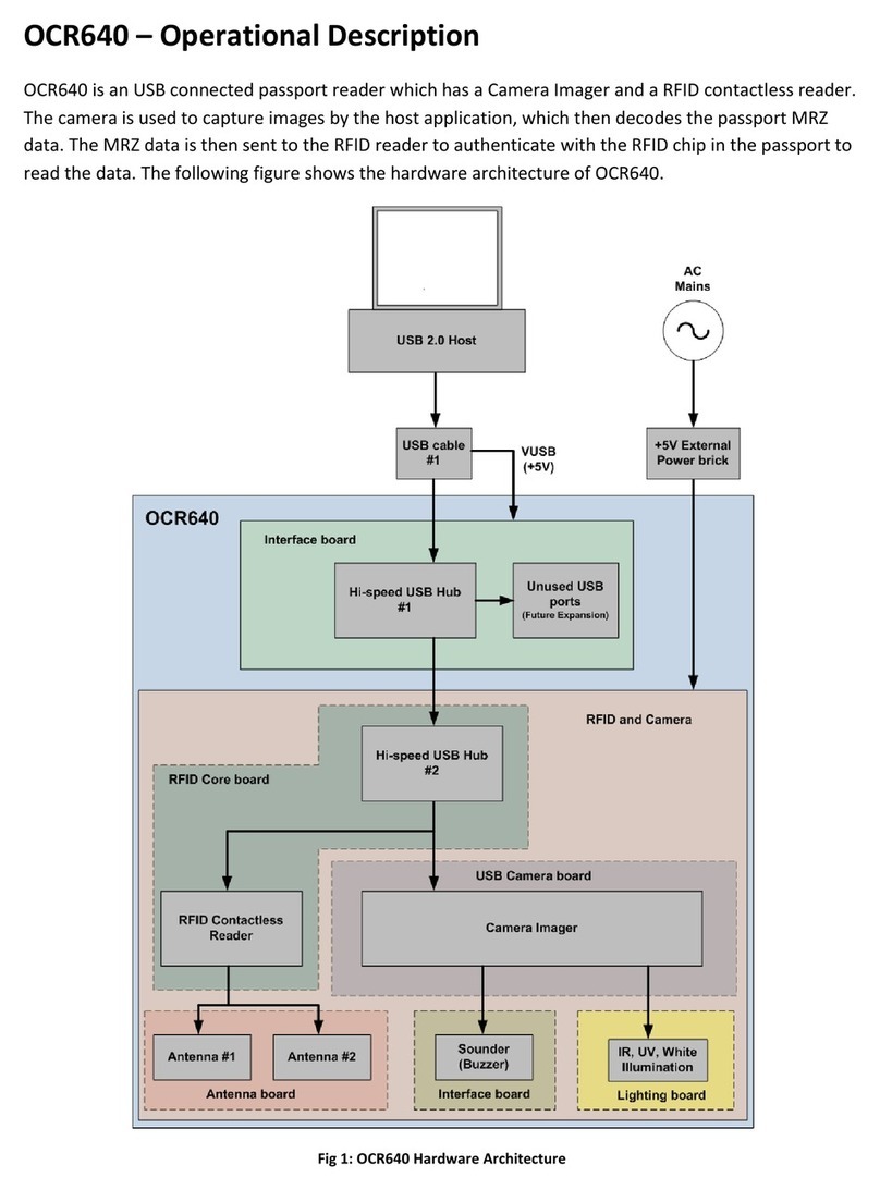
Access OCR640 Operational description
Fujitsu
Fujitsu M4097D - Fb 50PPM SCSI A3 Dupl 100Sht Adf Installation procedures
Brother
Brother DSmobile DS-640 Quick setup guide
Panasonic
Panasonic KV-S1028Y Additional information
Motorola
Motorola DS9208-1D Product reference guide
