PSR PAT ANTI-TWO-BLOCK Specifications

INSTALLATION, OPERATOR’S & TROUBLESHOOTING
MANUAL
PAT ANTI-TWO-BLOCK


TABLE OF CONTENTS
1.
GENERAL INFORMATION.........................................................................................................1
2.
WARNINGS.................................................................................................................................1
3.
OPERATION ...............................................................................................................................2
SYSTEMDESCRIPTION.........................................................................................................2
CONTROL IDENTIFICATION ..................................................................................................2
PRE-OPERATION INSPECTION.............................................................................................4
OPERATIONAL TESTS...........................................................................................................6
4
INSTALLATION ..........................................................................................................................7
SYSTEMKITS.........................................................................................................................7
INSTALLATION, HYDRAULIC CRANE....................................................................................7
DRAWING 1. 031-300-060-653 A2B CONSOLE INSTALLATION KIT - PARTS LIST..................8
DRAWING 1. 031-300-060-654 A2B MAIN BOOM INSTALLATION KIT - PARTS LIST...............9
DRAWING 3. 031-300-100-443 A2B MOUNTING KIT - PARTS LIST........................................11
DRAWING 4. 031-300-060-653 A2B CONSOLE INSTALLATION KIT - ELECTRICAL
DIAGRAM..................................................................................................................................12
DRAWING 5. 031-300-100-654 A2B MAIN BOOM INSTALLATION KIT - ELECTRICAL
DIAGRAM..................................................................................................................................13
INSTALLATION, LATTICE CRANE........................................................................................14
DRAWING 6. 031-300-101-224 KIT, A2B MAIN BOOM LATTICE RETROFIT - PARTS LIST....14
031-300-101-225 KIT, A2B JIB LATTICE RETROFIT - PARTS LIST.........................................14
DRAWING 7. 031-300-101-224 KIT, A2B MAIN BOOM LATTICE RETROFIT - ELECTRICAL
DIAGRAM AND 031-300-101-225 KIT, A2B JIB LATTICE RETROFIT - ELECTRICAL
DIAGRAM..................................................................................................................................15
DRAWING 8. CONSOLE, A2B, W/LOCKOUT KEY SWITCH PARTS LIST................................16
DRAWING 9. 006-820-006-002 CABLE REEL, KT200 PARTS LIST..........................................17
LENGTH CABLEREPLACEMENT PROCEDURE .................................................................18
SLIP RINGREPLACEMENT PROCEDURE...........................................................................19
5
TROUBLESHOOTING ..............................................................................................................20
ANTI-TWO-BLOCK PROBLEM..............................................................................................20
ANTI-TWO-BLOCK THEORY..........................................................................................................................23
INSTALLATION, OPERATOR’S & TROUBLESHOOTING MANUAL
ANTI-TWO-BLOCK


GENERAL INFORMATION 1
1.
GENERAL INFORMATION
The PAT Anti–Two-block System has been designed to warn the crane operator of a two-blocking
condition of the crane. If a two-blocking condition is approached, the system will warn the operator by
sounding an audible alarm, lighting a warning light and locking out those functions which may
aggravate the crane's condition, whenever applicable.
NOTE: The term "two-block" is a crane term that refers to a condition when the load handling device
comes in contact with the boom head. This condition, if not prevented, may cause the wire rope to
break, allowing the load to fall. Either raising the load into the boom head, or telescoping the boom
without paying out hoist line can cause a "two- block" condition.
2.
WARNINGS
The PAT Anti-Two- Block System is an operational aid, which warns a crane operator of approaching
two-block conditions, which could cause damage to equipment and personal injury.
This device is not, and shall not be a substitute for good, sound operator judgment, experience and
use of accepted safe crane operating procedures.
The responsibility for the safe operation of the crane remains with the crane operator who shall ensure
that all warnings and instructions supplied are fully understood and observed.
Prior to operating the crane, the operator must carefully and thoroughly read and understand the
information in this manual to ensure that he or she knows the operation and limitations of the system
and the crane.
Proper functioning is dependent upon proper daily inspection and observations of the operating
instructions set forth in this manual. Refer to Section 4 of this manual.
3.
OPERATION
SYSTEM DESCRIPTION
The PAT Anti-Two-block System consists of an operating console, a cable reel, two-block switches
and all applicable wiring.
The anti-two-block switch(es) is (are) mounted at the head of the boom and boom extensions if
available. When the hook block contacts the weight, which means a two-block condition is
approaching, the hoist limit switch contacts open sending a signal that locks out the hoist up, boom up,
and tele out functions.
The cable reel, which is mounted on the boom base section, serves as an electrical conductor for the
anti-two-block switch signal.
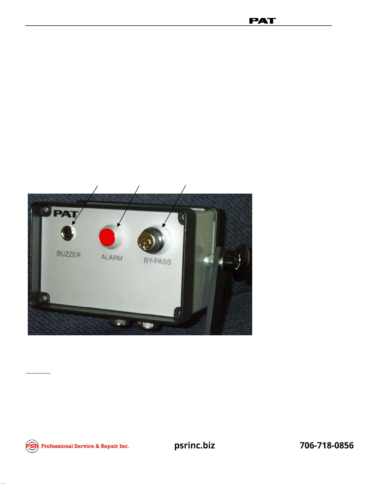
The operating console is located in the operator's cab in front of the operator. This unit contains
different controls, which are described in the following picture.
1.
Buzzer
2.
Alarm light button
3.
By-pass key switch
CONTROL
IDENTIFICATION
Figure 1 illustrates the controls of the PAT Anti-two-block System. The numbers of the illustration
correspond to the numbers in the following list, which describes the function of each control.
1. Buzzer: The BUZZER (1) is an audible alarm that sounds during an approaching two-block
condition of the crane. At the same time, the Anti-two-block Alarm Light (2) illuminates. The
following crane movements will be stopped concurrently; hoist up, telescope out and boom down.
(Whenever applicable) The audible alarm can be silenced temporarily by pushing the Alarm light
button (2).
2
INSTALLATION, OPERATOR’S & TROUBLESHOOTING MANUAL
ANTI-TWO-BLOCK
1
2
3

Since this switch deactivates the cut-off function of the anti-two-block system, the
following instructions shall be adhered to:
The by-pass key shall be used with discretion, because unwarranted use to
override the control lever lockout system can result in harm to the crane
and endanger property and/or person.
Never use the by-pass key to either overload or operate the crane in a
range that is not permissible.
PRE-OPERATION INSPECTION 3
2. Anti-Two-block Alarm Light and Alarm Stop Button: The ALARM LIGHT BUTTON serves a
dual purpose. First, a red warning light illuminates when the anti-two-block limit switch contact
opens. This indicates that a two-blocking condition is approaching. At the same time, the BUZZER
(1)
will sound and the following crane movements will be stopped concurrently: hoist up, telescope
out and boom down. (Whenever applicable) Second, it acts as an alarm stop button, which allows
the buzzer to be silenced temporarily.
3. By-Pass Key Switch: The BY-PASS KEY SWITCH (3) can deactivate the cut off function of the
anti-two-block momentarily to allow the crane operator to override the control lever lockout. This
function can only be engaged by using the matching key. The BY-PASS SWITCH has 2 positions,
which are more specifically described as follows:
The neutral position is engaged when the plunger is out and the key can be removed, as
shown below. In this position, the by-pass key switch does not influence the anti-two-block
control lever lockout.
This position bypasses the anti-two-block control lever lockout. This function can only be
engaged by using the matching key. In this position, the cut off function of the system is
deactivated. To activate the switch, the key has to be turned clockwise for about 45 degrees
and plunger push in, then turned back to the middle position to lock it in place (as shown
below). After activating the by-pass key switch, the alarm light will constantly blink, indicating
that the cutoff function has been deactivated. During this operation, with the anti-two-block
switch activated, the alarm light will blink with a higher frequency. The BUZZER (1) for
approaching two-block conditions will be illuminated at all times.
Failure to re-position the anti-two-block switch weight will prevent the system from functioning
properly. No weight shall be on the main hoist anti-two-block switch when the boom extension
is being used.
PRE-OPERATION INSPECTION
Prior to operating the crane, the following checks must be made:
1.
Check the cabling connections to the various parts of the system for physical damage.
2.
Check the spring-loaded cable reel to ensure it is free to rotate, has proper tension and is spooled
properly.
3.
Check the anti-two-block switches and weights for freedom of movement.
4.
Check the anti-two-block switch weight for proper installation on the hoist load line. The hoist line
runs through the A2B weight. With even parts of hoisting line, the weight shall be attached to the
dead-end line. With odd parts of hoisting line, the weight shall be attached to the line of lowest
speed.
5.
Check the A2B conditions for main/auxiliary hoist operation with the following instructions:
1)
If the crane works with only the main boom, the by-pass plug must be installed in the main
boom junction box.
2)
If the crane works with an extension:
a)
If the boom extension is not in the operating position, the by-pass plug must be installed in
the main boom junction box. The weight shall be installed on the main hoist anti-two-block
switch.
b)
If the boom extension is in the operating position and the load line is being used on the main
boom, the connecting cable must be installed between the junction boxes on the main boom
and extension. Weights must also be attached to the anti-two-block switches on both the
main boom and boom extension.
c)
If the boom extension is in the operating position and no load line is being used on main
boom, to prevent injury or damage to equipment, the weight shall be removed from main
boom switch. In that case the anti-two-block switch has to be locked with the red Anti-two-
block Retainer (See number 6 in this section).
4
INSTALLATION, OPERATOR’S & TROUBLESHOOTING MANUAL
ANTI-TWO-BLOCK
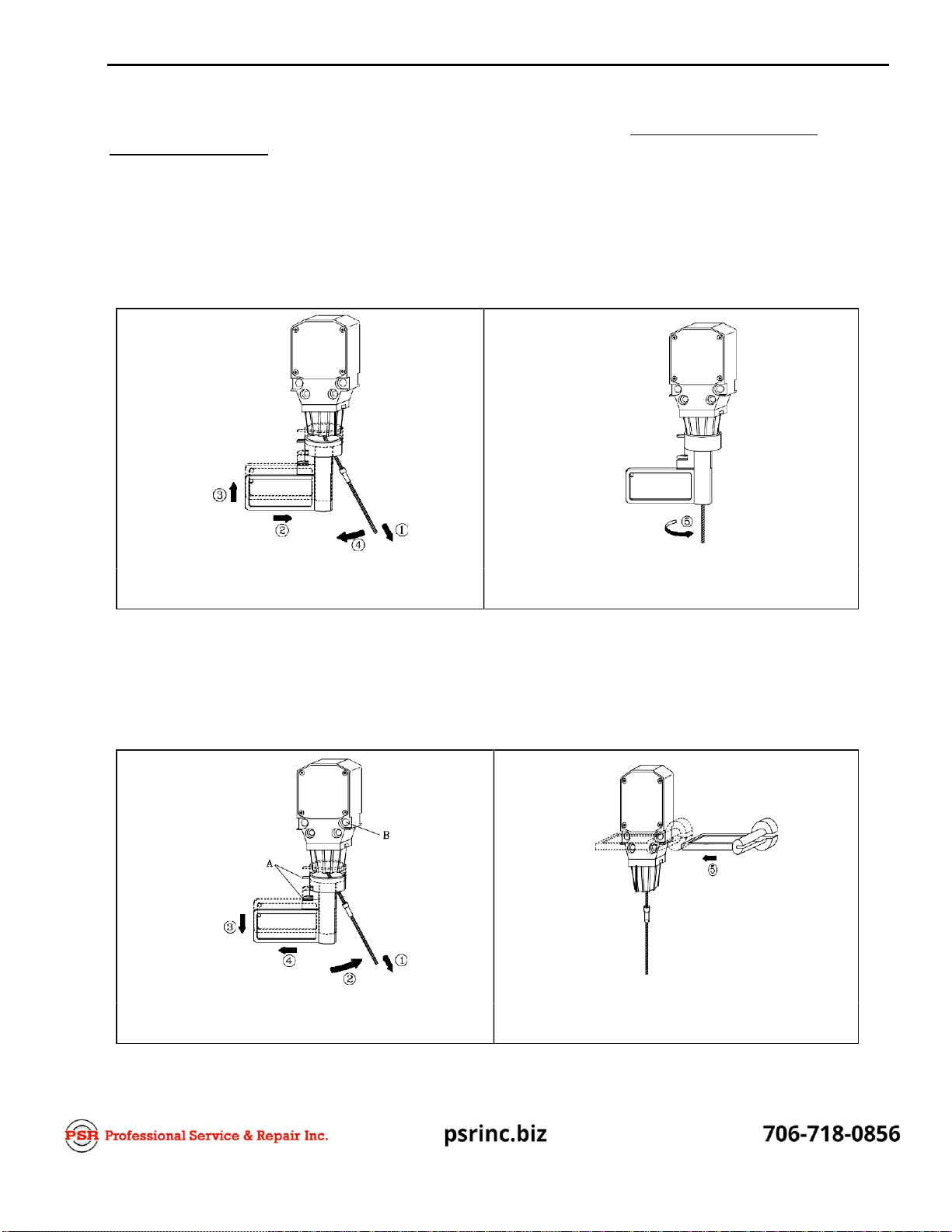
Fig. 1: Setting of Anti-two-block Retainer in
Locking Position
Fig. 2: Retainer in Locking Position
PRE-OPERATION INSPECTION 5
6.
Check the installation of the A2B retainer when applicable. - See Numbers 4 and 5 of Pre-
Operation Inspection, above.
Installation of Anti-two-block Retainer in Locking Position (Figures 1 and 2)
1.
Pull the cable out of the switch and bend back parallel to the boom and hold .
2.
Slide the retainer from left side with its slot over the cable between the crimped stop and the switch
. Push it firmly straight onto the cable guide of the Anti-two-block switch .
3.
Straighten the cable completely into the slot and release the cable.
4.
Turn the flag of the retainer for the operator’s best visibility. .
Removal and Storage of Anti-two-block Retainer (Figures. 3 and 4)
1.
Pull the cable out of the switch and bend back parallel to the boom and hold .
2.
Move the retainer down and then left to remove it from the Anti-two-block switch. Release the
cable.
3.
For storage, slide the retainer from the right side over the Anti-two-block switch until the clips (A)
lock into the holes (B).
Fig. 3: Removal of the Anti-two-block
Retainer
Fig. 4: Retainer in Storage Position
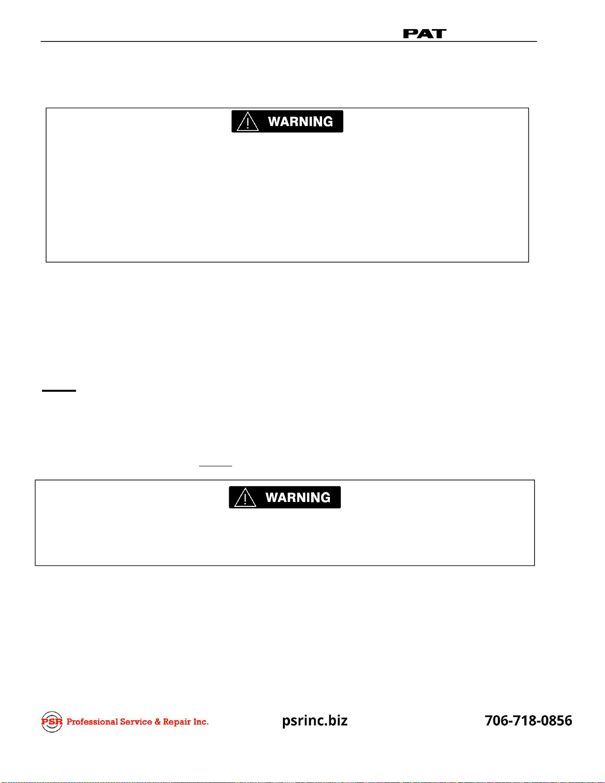
The following tests must be performed carefully to prevent personal injury or damage to the
machine. Proper system functioning requires successful completion of these tests before
operating the machine.
If the operator cannot clearly see the hook block approaching the boom head, an assistant
must watch the hook block.
The operator should be prepared to stop the machine immediately, if the system fails to
function properly by lighting the red warning light and /or sounding the audible alarm.
OPERATIONAL TESTS
The operation test will test and verify the anti-two- block switch(es)is (are) functioning properly. This
test should be completed periodically or any time there is an indication of uncertainty for operation.
1.
Start the crane in accordance with crane operator’s manual.
2.
Verify that the anti-two-block indicator and audible alarm function properly by manually lifting the
weight attached to the A2B switches on the crane. When the weight is lifted, the audible alarm
should sound, and the anti-two-block alarm light should light. (See SAE J1305 for two-block
warning and limit system operation)
3.
Slowly raise the main boom hook block to bring it into contact with the A2B switch weight.
NOTE: If the operator cannot see the load handling device approaching the boom nose, he shall have
an assistant (signal person) watch the load handling device. The operator shall be prepared to
stop the machine immediately if the system fails to function properly by lighting the red
warning light, sounding the audible alarm and locking the hoist up function.
When the hook block contacts the weight, the red anti-two-block indicator should light and the
audible alarm should sound. NOTE: The hoist up function of the crane will be disabled. Lower the
hook block to eliminate the two-block condition.
If the light and audible alarm do not function as described and the crane movements are not
stopped, the system is not working properly. The malfunction must be corrected before
operating the crane.
6
INSTALLATION, OPERATOR’S & TROUBLESHOOTING MANUAL
ANTI-TWO-BLOCK

INSTALLATION 7
4
INSTALLATION
SYSTEM KITS
This Installation Manual shows the approximate location of components and wiring diagrams required
for system operation. This manual has two different system component and wiring diagrams;
therefore, use the drawings that match your system, as shown below:
1.
031-300-100-432 SYSTEM, A2B HYDRAULICMAINBOOM
Component Item Qty Component Description
031-300-100-653 1.0 KIT, A2B CONSOLE
031-300-100-654 1.0 KIT, A2B MAINBOOM
031-300-100-443 1.0 KIT, A2B MAINBOOM MOUNTING (15R)
031-300-100-201 1.0 MANUAL, A2B SYSTEM RETROFIT INSTALLATION
2.
A2B LATTICE MAIN & EXT BOOM KITS
Component Item Qty Component Description
031-300-101-224 1.0 KIT, A2B MAIN BOOM LATTICE RETROFIT
031-300-101-225 1.0 KIT, A2B JIB LATTICE RETROFIT
031-300-100-201 1.0 MANUAL, A2B SYSTEM RETROFIT INSTALLATION
NOTE: Prior to starting the installation, it is advised to review the drawings and define the
component locations on the crane. The Anti-two-block System must be tested after completing
installation. Complete Section 3.3 Pre-Operation Inspection and Section 3.4 Operational Tests
in the Operator’s portion of this manual, Section 3. Operation.
3) Prior to operating the crane, the operator must carefully read and understand the information in
Section 3. Operation, in order to know the operation and limitations of the Anti-two-block System.
INSTALLATION, HYDRAULIC CRANE
Select the correct section for your crane and use the anti-two-block system drawings for component
installation and wiring system.
031-300-100-432 SYSTEM, A2B HYDRAULIC MAINBOOM
Drawing 1. 031-300-060-653 A2B Console Installation Kit - Parts List
Drawing 2. 031-300-100-654 A2B Main Boom Installation Kit - Parts List
Drawing 3. 031-300-100-443 A2B Mounting Kit - Parts List
Drawing 4. 031-300-060-653 A2B Console Installation Kit - Electrical Diagram
Drawing 5. 031-300-100-654 A2B Main Boom Installation Kit - Electrical Diagram
Optional jib kits are not shown on parts list. (The additional components are available upon request.)
NOTE: CONTACT CRANE MANUFACTURER FOR WELDING INSTRUCTIONS PRIOR TO
WELDING ON BOOM.
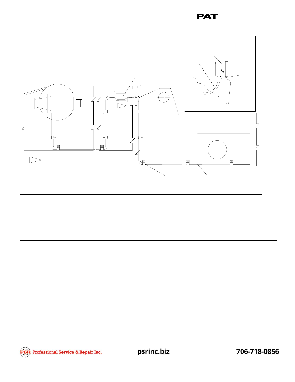
DRAWING 1. 031-300-060-653 A2B CONSOLE INSTALLATION KIT - PARTS LIST
VIEWOFCONSOLE
MOUNTEDINCAB
P A T
2,3,4,5
1
13 1
14
15
16 9
10
11
12
TO PLUG
AT BOOM BASE
CLEANELECTRICALCONTACTSAND
CONNECTORSOFALLFOREIGN
MATERIAL SUCH AS GREASE, OIL,
ANDDIRTBEFORECONNECTING.
CONTACTCRANEMANUFACTURERFORWELDINGINSTRUCTION
PRIORTOWELDINGONTHEBOOM.
7,8,9,10,11
TO CONSOLE
16 IN CAB
NO. PART NO. QTY DESCRIPTION
01 050-000-060-100 1 A2B CONSOLE, 12VW/ LOCKOUT KEYSWITCH
02 000-301-022-100 1 PLUG, 10 PIN
03 000-301-025-102 1 INSERT, 10 PINFEMALE
04 000-214-261-613 1 REDUCER, PG16-13.5
05 021-441-131-013 1 STRAIN RELIEF, PG13.5 W/ RED/WHTINSERT
06 000-610-020-371 5 TIE WRAP,VINYL
07 000-325-040-916 5 CABLE CLAMP, 9/16"
08 002-350-207-250 5 STUD, 1/4-20 X 7/8WELD
09 000-207-010-070 7 FLAT WASHER, 1/4
10 000-208-040-070 7 LOCK WASHER, 1/4
11 002-060-100-705 7 NUT, 1/4-20 HEX
12 002-051-107-255 2 SCREW, 1/4-20 X 1 HEXHEAD
13 031-010-100-153 2 TERMINAL, MALE .250 DC/MI 14-16 AWG
14 031-010-100-154 4 TERMINAL, FEMALE .250 DC/FI 14-16AWG
15 031-300-100-146 14' CABLE, 4 X 1.5S.S.
16 031-300-100-148 22' CABLE, 7 X 0.5D.S.
8
INSTALLATION, OPERATOR’S & TROUBLESHOOTING MANUAL
ANTI-TWO-BLOCK
1
8,9
0,11,12
20,21
21,22
42,43,44,45
13,14,15,1
5. 5"TO
P AT
26
1 1 /2
TYP.
SPAC
AT 55
18
2-7/8
30
FRONT
EAR
17
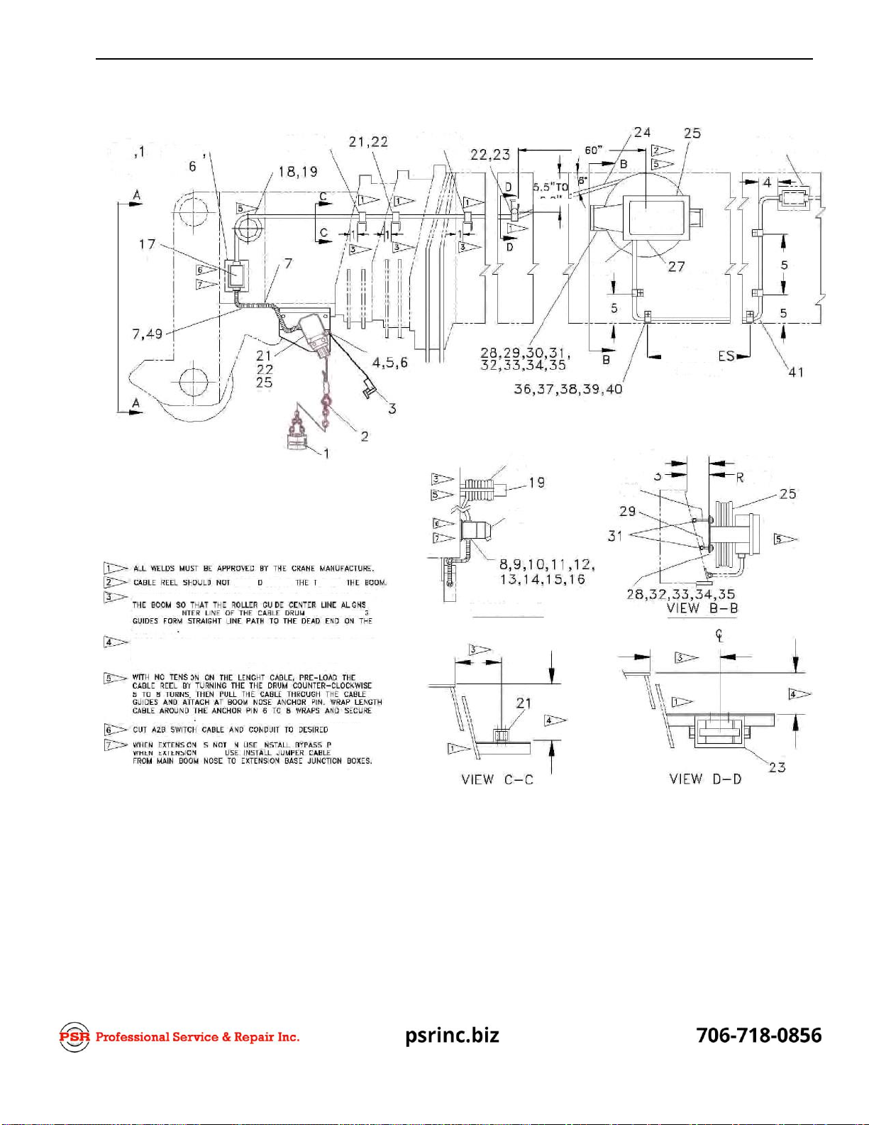
PDSITIO N *H E BASE SEC*I0 N ROLLER GUI DE, A DIST ANCE FRO M
VIEW A—A.
P05%ON HE?H?OF I0E,BA5, ,CTO’, R0,iLE„, DDE ?0?H,I
REEL. THE IABLE’WlLL HAYE AN ANGLE OF APPROXlPATELT 5’
INSTALLATION, HYDRAULIC CRANE 9
DRAWING 1. 031-300-060-654 A2B MAIN BOOM INSTALLATION KIT - PARTS LIST

NO. PART NO. QTY DESCRIPTION
01 068-000-050-078 4 HOOK BOLT, 3/8-16 X4
02 068-000-050-077 2 HOOK BOLT, 3/8-16 X 23/4
03 000-207-010-105 12 FLAT WASHER, 3/8
04 000-208-040-100 12 LOCK WASHER,3/8
05 002-060-101-005 8 NUT, 3/8-16 HEX
06 002-051-110-255 4 SCREW, 3/8-16 X 1 HEXHEAD
07 002-350-207-255 15 STUD, 1/4-20 X 1WELD
08 002-060-100-705 15 NUT, 1/4-20 HEX
09 000-208-040-070 15 LOCK WASHER,1/4
10 000-207-010-070 15 FLAT WASHER, 1/4
11 000-301-023-100 1 RECEPTACLE, 10 PIN
12 004-000-050-011 1 MOUNTING PLATE, 10 PINRECEPTACLE
13 002-053-904-127 8 SCREW, #10-24 X 1/2 ROUNDHEAD
14 000-208-040-053 8 LOCK WASHER, #10
15 000-301-025-101 1 INSERT, 10 PINMALE
16 000-214-340-016 2 HOLE PLUG, PG16
17 006-820-006-002 1 CABLE REEL, KT200STANDARD
18 031-300-100-148 20' CABLE, 7 X 0.5D.S.
19
031-002-100-053 1 A2B RETAINER FLAG W/ METALINSERT
20
031-300-100-269 1 DECAL "WARNING" A2BSWITCH
21
031-002-060-011 1 A2B SWITCH, (NEW STYLE) W/CRIMP
22 031-300-100-105 2 SCREW, 5/16-18 X 1 1/2 SOCKET CAP,STAINLESS
23 031-000-050-004 1 PLATE, A2B SWITCH, ADAPTER (PRIMERED)
24 002-070-100-805 2 FLAT WASHER, 5/16
25 000-208-040-080 4 LOCK WASHER, 5/16
26 000-051-106-185 2 SCREW, 5/16-18 X 3/4"HEX
27 031-300-100-110 10' CONDUIT, 1/4" BLACKFLEX
28 000-325-040-916 12 CABLE CLAMP, 9/16"
29 004-000-050-010 1 MOUNTING PLATE, 6 PINRECEPTACLE
30 000-301-022-296 1 RECEPTACLE, 6 PIN
31 000-301-022-060 1 PLUG, 6 PIN
32 000-301-025-061 1 INSERT, 6-PIN MALE
33 000-301-025-062 1 INSERT, 6-PIN FEMALE
34 000-214-340-013 1 HOLE PLUG, PG13.5
35 000-214-261-609 2 REDUCER, PG16-9
36
021-441-060-409 1 STRAIN RELIEF, PG9 YELLOW/WHITE
37
068-000-050-072 1 PLATE, CABLE REEL MOUNTING(PRIMERED)
38
021-441-090-909 1 STRAIN RELIEF, PG9, 3mm WHITE
39 000-214-261-613 1 REDUCER, PG16-13.5
40
031-004-100-028 4 CABLE GUIDE, SMALL,MAINBOOM
41
031-004-100-033 1 CABLE GUIDE, LARGE, MAINBOOM
42 000-610-020-371 5 TIE WRAP, VINYL, 1/4 X13"
43 000-401-024-470 1 RESISTOR, 4.7K
44 021-441-131-013 2 STRAIN RELIEF, PG12.8,RED/WHITE
45 031-300-100-064 4 BUSHING, FOR HOOKBOLT
46 031-002-100-048 1 LANYARD, RED
47 031-300-100-037 1 CHAIN CONNECTOR, QUICK LINK, 27/16"
48 003-100-210-012 1 WEIGHT & CHAIN, A2B W/SHACKLE
10
INSTALLATION, OPERATOR’S & TROUBLESHOOTING MANUAL
ANTI-TWO-BLOCK

5
INSTALLATION, HYDRAULIC CRANE 11
DRAWING 3. 031-300-100-443 A2B MOUNTING KIT - PARTS LIST APPROX.
1 2 2 60
3
A
P A T
1 1 1 A
4
5
1 1/ 2
TYP.
5
1
3
ROLLERGUIDESONBASESECTION
1 BECENTEREDONCABLEDRUM,
INGGUIDESTOFORMSTRAIGHT
TODEADENDON
WHENOPTIONALSWINGAWAY
SIONORROOSTERSHEAVEIS NOT
USE.STOWEXTENSIONCORDAND
STALLJUMPERPLUGIN BOOMNOSE
RECEPTACLE. WHEN OPTIONAL
AWAYEXTENSIONORROOSTER
IS IN USE,REMOVEANDSTOW
PLUG.INSTALLJUMPERCORD
BOOMNOSERECEPTACLEAND
AWAYEXTENSIONORROOSTER
RECEPTACLE.
POSITIONHEIGHTOFROLLERGUIDE
OBTAINCABLEREELLINEPATH
IS PARALLELTOTOPSURFACEOF
SECTIONS.
CUTA2BSWITCHCABLEAND
TODESIRED
CLEANELECTRICALCONTACTS
CONNECTORSOFALLFOREIGN
MATERIALSUCH AS GREASE,
ANDDIRTBEFORE
CONTACTCRANEMANUFACTUREFORWELDING
PRIORTOWELDINGONTHE
3
VIEWA- A
NO. PART NO. QTY DESCRIPTION
01 031-004-050-037 1 BRACKET, CABLE GUIDE ANGLE(7.5')
02 031-004-050-047 4 BRACKET, CABLE GUIDE ANGLE (7.5' X8")
03 031-004-050-057 1 BRACKET, LENGTH CABLE 1" ID X 1/8"WL X 8 1/2"
2
4
3

12 INSTALLATION, OPERATOR’S & TROUBLESHOOTING MANUAL ANTI-TWO-BLOCK
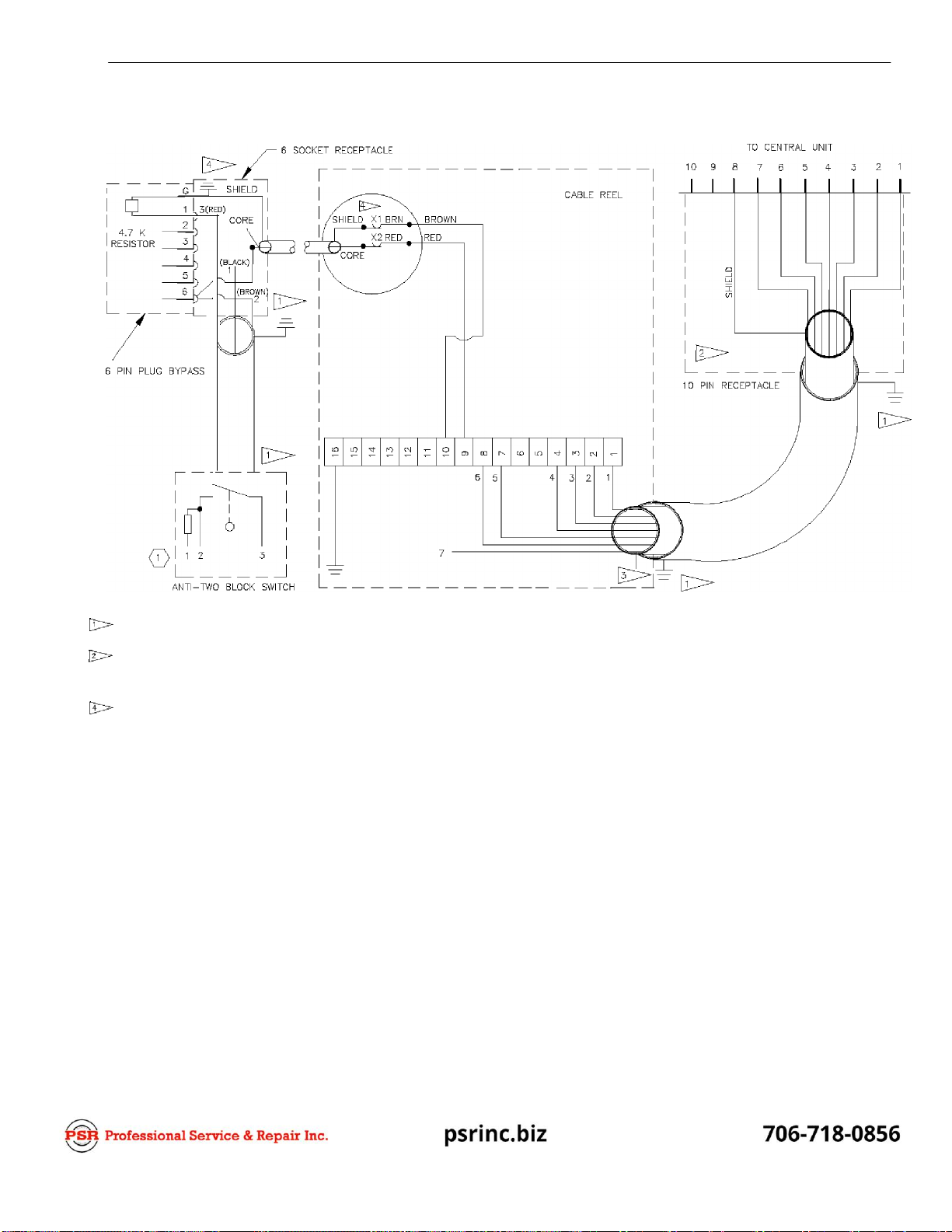
DRAWING 4. 031-300-060-653 A2B CONSOLE INSTALLATION KIT - ELECTRICAL DIAGRAM
INNER SHIELD
(Is)
INSULATED
AND CONNECT E D AS SHOWN.
OUTER SHIELD GROUNDED Y/ITH
COMPONE NT STRAIN RELIEF
CRANE ELECTRIC CONNECTION —
COMPONENTS ARE 0PT|0NAL AND
NOT SUPPLIED BT PAT.
RE*ER TO CRANE ELECTRIC
SCHEMATICS.
EACH 30LENQID VALVE 0R
MAC N ET DEVICE TQ BE INSTALLS D
Y/ITH DI0DE IN 4003....IN4007 AS
SH0Y/N.
Y/IRE ENDS INSULATED AND NOT
CONNECTED (WIRE 1—4, & 7).
' "10AMP
b!rusE
A2B—CONSOLE
050 000 060 00
19
i0 PIN PLUG
TO MAN BOOM REAR
INSTALLATION, HYDRAULIC CRANE 13
DRAWING 5. 031-300-100-654 A2B MAIN BOOM INSTALLATION KIT - ELECTRICAL DIAGRAM
N Q TES :
OU TER SH
I
ELD GROUNDED A* STRAI N
RELIEF C 0 N N EC*OR
I
NN
ER
SH
I
ELD
INSULATED
AND CON
N
EC*ED
AS S H0WN
INNER SHIELD CUT OFF AND TAPED
OUTER SH OLD NSU LACED AND CON N EC*LD
AS SHOWN
SWITC H PREWIRE D AND PO*TED
WELD STUD W/
CONNECT PLUG FROM SWITCH
TO THE JUMPER CABLE
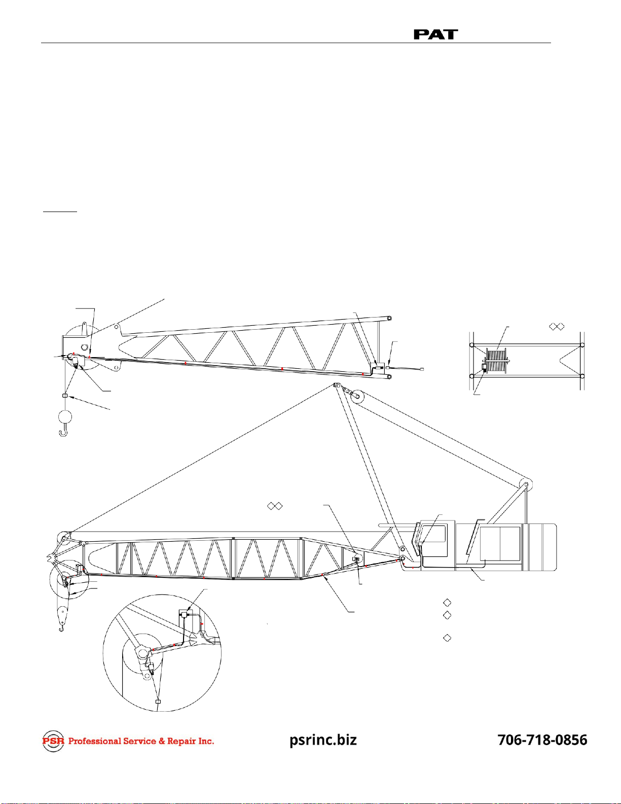
CABLE REEL 1 2
CONDUIT
031-300-060-051
JUMPER CABLE FROM
JIB TO MAIN BOOM
BOOM TIP
BOOM BASE
A2B SWITCH ASSEMBLY
031-300-100-458
A2B SWITCH WEIGHT
CONNECT PLUG FOR CABLE
FROM A2B CONSOLE
TOP VIEW
031-300-101-225 A2B JIB KIT
1 2 CABLE REEL
031-300-060-049
A2B CONSOLE
A2B SWITCH 031-002-060-011
A2B SWITCH WEIGHT
4 CONDUCTOR CABLE
FOR CRANE POWER
JUNCTION BOX
531-300-100-112
2 CONDUCTOR CABLE
ASSEMBLY TO CABLE REEL
031-300-060-050
WELD STUD W/
9/16" CABLE CLAMP
031-300-101-224 A2B MAIN BOOM KIT
NOTES:
1
ALLOW AMPLE CABLE LOOP TO COVER
ALL MAST ANGLES.
2
TO CONNECT CABLE REEL TO MAIN BOOM NOSE;
UNROLL CABLE FROM CABLE REEL AND SCREW
2 PIN RECEPTACLE PLUG INTO THE MAIN BOOM
NOSE JUNCTION BOX.
3
REFER TO OPERATOR'S HANDBOOK FOR PROPER
USE OF A2B SWITCH WEIGHT AND RETAINER FLAG.
INSTALLATION, LATTICE CRANE
SYSTEM, A2B LATTICE MAIN & EXT BOOM KITS
Drawing 6. 031-300-101-224 Kit, A2B Main Boom Lattice Retrofit - Parts List and
031-300-101-225 Kit, A2B Jib Lattice Retrofit - Parts List
Drawing 7. 031-300-101-224 Kit, A2B Main Boom Lattice Retrofit - Electrical Diagram
and 031-300-101-225 Kit, A2B Jib Lattice Retrofit - Electrical Diagram
Optional jib kits are shown on parts list (the additional components available upon request)
NOTE: CONTACT CRANE MANUFACTURER FOR WELDING INSTRUCTION PRIOR TO WELDING
ON BOOM.
DRAWING 6. 031-300-101-224 KIT, A2B MAIN BOOM LATTICE RETROFIT - PARTS LIST
031-300-101-225 KIT, A2B JIB LATTICE RETROFIT - PARTS LIST
14
INSTALLATION, OPERATOR’S & TROUBLESHOOTING MANUAL
ANTI-TWO-BLOCK

This manual suits for next models
6
Table of contents


