manuals.online logo
Brands
  1. Home
  2. •
  3. Brands
  4. •
  5. Simplex
  6. •
  7. Security System
  8. •
  9. Simplex 4099-5211 User manual

Simplex 4099-5211 User manual

1/2 Doc. version 1.0
Outdoor Isolated Callpoint
Installation
The Outdoor Isolated Callpoint is an addressable weatherproof manual
callpoint.
The callpoint signals the condition of a switch contact that is operated by
pressing on a deformable element. After activation the deformable element
is not destroyed and the callpoint can be reset.
The unit features a short-circuit isolator and meets the requirements of
EN54 Pt. 11 and EN54 Pt. 17.
Details of the Status LED and activation are on Page 2.
Item Order Number
MCP - Isolator Outdoor 4099-5211
Resettable element (pack of 1) 515.001.127
1 Find the back box (not pictured). This is supplied with cable entry holes
fitted with screw in blanking plugs. Choose appropriate cable entry
holes and remove the plugs. (The holes must be at the top and bottom
of the back box once mounted.)
2 Screw plugs into the unused entry holes, complete with the provided
plastic washers. For maximum sealing around the pugs apply a thread
sealant such as Loctite 5331.
3 Fit appropriate glands to the entry holes. Choose glands that fit the
entry holes (20 mm diameter) and provide a good seal round the loop
cabling.
4 If required fit the metal earthing plate. This may be required to maintain
electrical continuity across conduit sections, for example. The plate fits
to the rear of the back box and angles around to the top and bottom of
the back box, where it features holes corresponding to the cable access
holes. The plate is held in place by the fittings made to the cable access
holes.
5 Mount the back box to the wall using the supplied screws. Mount the
box with the cable entry hole at the bottom for best weatherproofing.
6 Feed the loop wires into the back box through the access holes.
7 If necessary make connections to the back box’s earth terminal. You
can connect the loop left and right screens to this to maintain continu-
ity.
8 Remove the ‘Push-fit connector’ from its socket and connect the loop
wires into it.
9 Now start to work with the callpoint itself. Connect an 801AP MX
Service Tool or an 850EMT into the programming port, noting the ori-
entation. Program the unit with the ID defined in the site configuration.
10 Ensure the rubber gasket is correctly seated in the channel on the rear
of the callpoint.
11 Align the callpoint to the back box and insert the push-fit connector.
12 Place the callpoint squarely over the back box and carefully push it into
place until the locating clips engage.
13 Insert the four back box locking screws.
76.53
83.8
04.5 mm Fixing Holes
3 Places
Status LEDPress here to activate
+ -
Loop
+ -
Programming
Port
Back box lock
screws here
(4 similar
locations)
Push-fit
Connector
To check the status
To activate
To test
To reset
Simplex Outdoor Isolated Callpoint
120.515.787_SPX-D-MCP830-DS. doc. version 1.0. 9. April 2018.
©2018 Johnson Controls. All rights reserved. All specifications and other information shown were current as of
document revision date and are subject to change without notice.
www.simplex-fire.com
Tyco Fire & Security GmbH, Victor von Bruns-Strasse 21, 8212 Neuhausen am Rheinfall, Switzerland
Operation
To remove the unit from the backbox
Maintenance
Specifications
Approvals
All required Declarations and certificates are publicly available on the website www.simplex-fire.com and are searchable by number or model name.
The above fire detection products are components designed for use in Addressable Systems exclusively available to registered partners only. They are intended for installation
by trained registered personnel only. Systems should be installed and configured according to local regulations.
The “Status LED” is shown on the previous page, its conditions are: ”not
activated” – this is normal; “activated yellow” – there is a short circuit on
the loop. This must be rectified as quickly as possible; “activated red” – the
callpoint has been activated, indicating that there is a fire alarm state within
the building.
To activate the callpoint press on the position marked (large dot). This
allows a spring to push the plastic element downwards, so closing a switch
and triggering a signal to the control panel.
A test/reset key is provided to activate the callpoint for testing. Insert this
into the slot in the bottom of the unit and pull the sliding plate (lower half
of the front face) downwards. (Note this potentially causes an alarm).
Remove the key.
The deformable element also allows you to test by activating the callpoint
as normal. This is non-destructive.
To reset the callpoint, follow the ‘To test’ procedure above –pulling the
sliding plate downwards allows the element to snap back to its non-
deformed state.
To replace the glass or deformable element
Follow the ‘To test’ procedure above. Pull down further on the sliding plate
until it is free of the unit. Remove the deformable element, pulling away
the bottom first. Fit the replacement then push the sliding plate upwards
until it snaps back into place.
1 Remove the back box locking screws.
2 Gently lever the callpoint away from the back box by twisting a flat
bladed screwdriver in the slots between them.
Parameter Value Parameter Value
System Compatibility Use only with the Simplex SX501 Fire
Alarm Controller
Operating Humidity Up to 95 %.non-condensing
Environment Outdoor applications Dimensions (HWD) 93 x 97.5 x 73 mm
Operating Temperature -25 to +70 oCWeight 240 g
Storage Temperature -30 to +70 oCIP Rating IP67
Material Flame Retardant ABS, glass reinforced
CPR CPR Approval European Type Approvals
Declaration of Performance EN54-11 EN54-17 LPCB
DoP-2015-4170  
Other Simplex Security System manuals

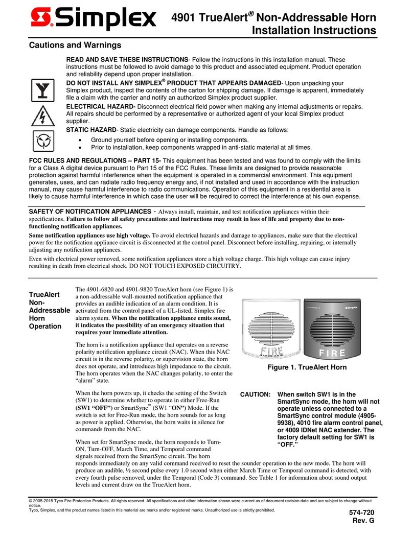
Simplex TrueAlert 4906-9207 User manual

Simplex

Simplex TrueAlert 4906-9207 User manual

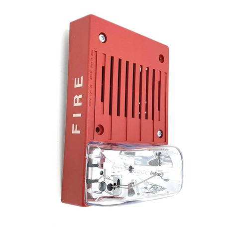
Simplex TrueAlert 4906-9202 User manual

Simplex

Simplex TrueAlert 4906-9202 User manual

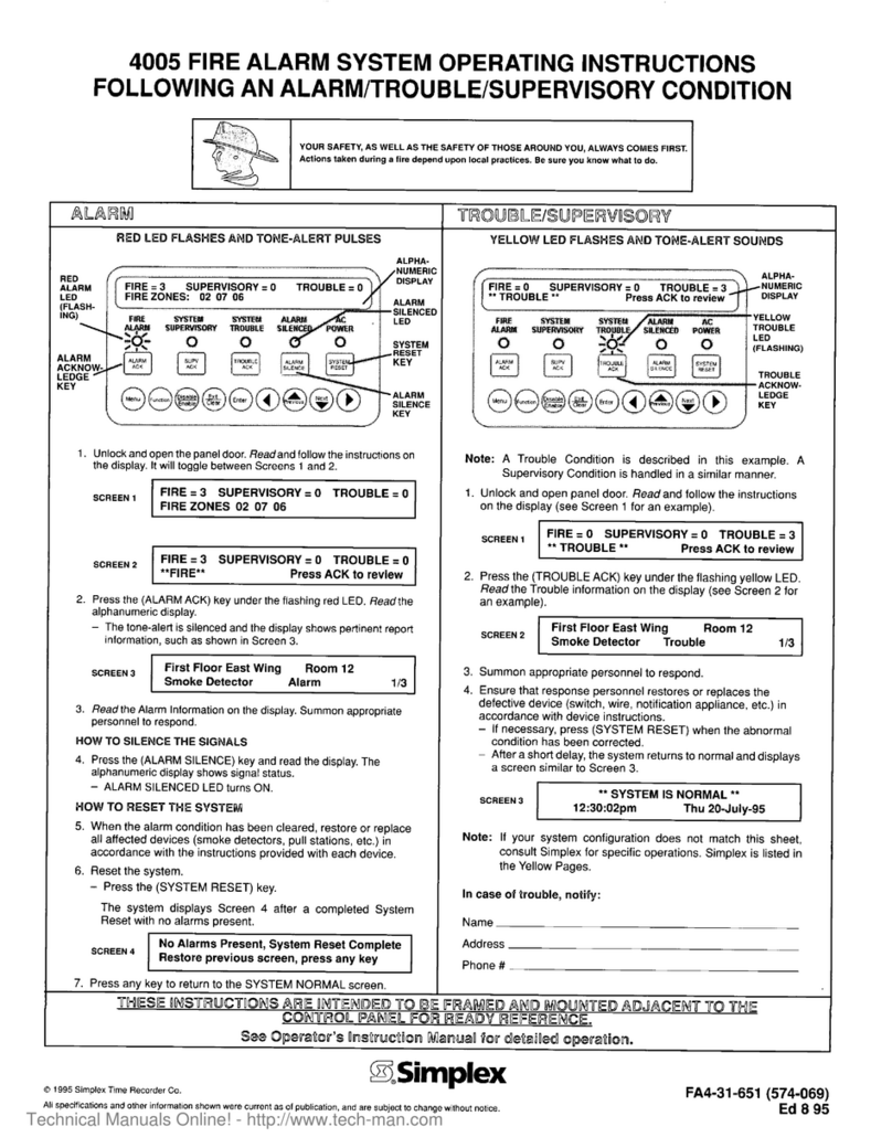
Simplex LifeAlarm 4005 Series User manual

Simplex

Simplex LifeAlarm 4005 Series User manual

Simplex SafeLINC 4100U Manual

Simplex

Simplex SafeLINC 4100U Manual

Simplex MINIPLEX 4100ES Series User manual

Simplex

Simplex MINIPLEX 4100ES Series User manual

Simplex MINIPLEX 4100ES Series User manual

Simplex

Simplex MINIPLEX 4100ES Series User manual

Simplex TrueAlert Isolator+ User manual

Simplex

Simplex TrueAlert Isolator+ User manual

Simplex TrueAlert 4901 Service manual

Simplex

Simplex TrueAlert 4901 Service manual

Simplex SafeLINC 4100 User manual

Simplex

Simplex SafeLINC 4100 User manual

Simplex TrueAlert 4906-9228 User manual

Simplex

Simplex TrueAlert 4906-9228 User manual

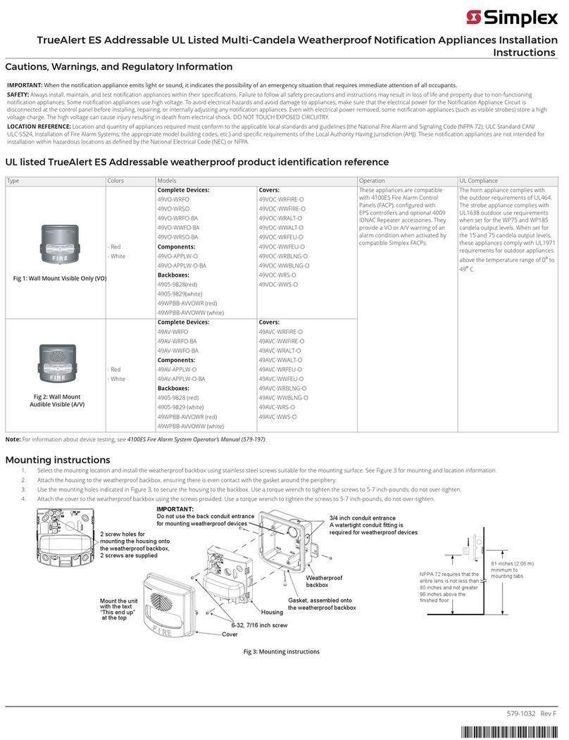
Simplex TrueAlert ES Service manual

Simplex

Simplex TrueAlert ES Service manual

Simplex 4010ES User manual

Simplex

Simplex 4010ES User manual

Simplex TrueAlert 4906-9208 User manual

Simplex

Simplex TrueAlert 4906-9208 User manual

Simplex 4010ES User manual

Simplex

Simplex 4010ES User manual

Popular Security System manuals by other brands

Lumex GF13702 Setup & operation instructions

Lumex

Lumex GF13702 Setup & operation instructions

B810 digicom 8D5896 manual

B810

B810 digicom 8D5896 manual

DSC GSM 1000 installation manual

DSC

DSC GSM 1000 installation manual

Altec SIRYNX RF quick start guide

Altec

Altec SIRYNX RF quick start guide

Wheelock RX-1419 installation instructions

Wheelock

Wheelock RX-1419 installation instructions

DSC PowerSeries Neo HS2TCHP installation instructions

DSC

DSC PowerSeries Neo HS2TCHP installation instructions

Triplett CamView PTZ 2 instruction manual

Triplett

Triplett CamView PTZ 2 instruction manual

Eldes ESIM4 user manual

Eldes

Eldes ESIM4 user manual

Viking MTG-10 product manual

Viking

Viking MTG-10 product manual

Satel SP-4002 quick start guide

Satel

Satel SP-4002 quick start guide

CSI Controls CSION 3R installation instructions

CSI Controls

CSI Controls CSION 3R installation instructions

Furuno BR-500 Product guide

Furuno

Furuno BR-500 Product guide

Brooks BARFS-1 owner's manual

Brooks

Brooks BARFS-1 owner's manual

Jasco 45246 user manual

Jasco

Jasco 45246 user manual

ADEMCO VISTA-100 user guide

ADEMCO

ADEMCO VISTA-100 user guide

DSC PowerSeries PC1404 Quick reference guide

DSC

DSC PowerSeries PC1404 Quick reference guide

iStaySafe iStaySafeAlert quick start guide

iStaySafe

iStaySafe iStaySafeAlert quick start guide

Vive LVA1074CHR user manual

Vive

Vive LVA1074CHR user manual

manuals.online logo
manuals.online logoBrands
  • About & Mission
  • Contact us
  • Privacy Policy
  • Terms and Conditions

Copyright 2025 Manuals.Online. All Rights Reserved.