DAITEM 473-29X User manual

,167$//$7,210$18$/
*60*356GDWDLPDJHWUDQVPLVVLRQ
GLDOOHU0RGHO;

6XPPDU\WDEOHRIFRGHVIRU$ODUP5HFHLYLQJ
&RPSDQ\$5&VHUYLFHFDOOV
3URJUDPPLQJFDOOVWRDQ$ODUP5HFHLYLQJ&R

WDNHRXWDVXEVFULSWLRQZLWKDVHUYLFHSURYLGHUEHIRUHKDQG((9RGDIRQHRHWF

4
2.1.1 Content of 473-29X
• GSM/GPRS dialler • 910-21X power supply (ENG 3A-055WT05_5 V DC/1 A)
• BATLi23 lithium power pack (2 x 3.6 V – 18 Ah) • Rechargeable battery 908-21X (BATT LiIon 3,6 V-700 mAh-FIL)
• Bag of accessories with cable clamps and grommets • Fixing bracket (on back of dialler)
2.1.2 Description of GSM/GPRS telephone dialler
2. Description and operation
2.1 Content and description
Location for cable
clamp (supplied)
Jack socket
for connecting
910-21X
adapter
Connection for
4 inputs/
2 outputs
Connection
for rechargeable
battery 908-21X
ADSL connection
Connector for
external antenna
(not supplied)
Fixing bracket
(on back of dialler)
Cable grommets (to be removed,
supplied in bag of accessories)
Screw cover
Unused
part
Back-lit LCD screen
Programming
keypad
Cover
Red/green LED Microphone
910-21X power supply
(ENG 3A-055WT05_5 V DC/1 A)
Use an adapter with power supply ENG 3A-055WT05.
This adapter must comply with the applicable
standards in your country.
• Back-lit LCD display
• 2 lines 16 characters long:
- 1st line: menu display,
- 2nd line: sub-menu display
Programming keypad Programming screen
Validate key
Cancel
and return key
Scroll keys for accessing different
menu parameters
Dialling keys
SIM card slot
Slot for
BATLi23 lithium
power pack
(supplied)
Dialler internal view
MAC address (ethernet)
Example MAC address
02985D6A3645

LQGLYLGXDOFRUUHVSRQGHQWVRUDQ$5&$ODUP5HFHLYLQJ&R
$5&
(WKHUQHW(WKHUQHWSDUDPHWHUV¿[HG,3DGGUHVV,3FRQQHFWLRQIRU$5&VHUYLFHFDOOV
RQO\

7HOHSKRQHWUDQVPLVVLRQFDQEHIROORZHGE\D/LVWHQLQSHULRGGXULQJZKLFKWKHFRUUHVSRQGHQWRU$ODUP5HFHLYLQJ&RFDQOLVWHQLQWR
ZKDWLVKDSSHQLQJDWWKHSURWHFWHGSUHPLVHVLQRUGHUWRYHULI\WKHDODUP

LQGLYLGXDOVDQGWRDQ$ODUP5HFHLYLQJ&R
IRUFDOOVWRDQ$ODUP5HFHLYLQJ&RWKHGLDOOHUHQGVWKHFDOOLQSURJUHVVDQGWUDQVPLWVWKH³'LVDUPHG´FRPPDQGLIWKHFDOOLVDQVZHUHG

$5&
$5&

9
3. Preparation
3.1 Opening the dialler
1. Using a Philips screwdriver, remove the screw cover
and loosen the screws.
3.2 Guarantee sticker
Remove the pre-cut part of the guarantee sticker and glue it to the extended guarantee request
form supplied with the control panel (if you are adding to an existing system, use the extended
guarantee request form supplied with the dialler).
2. Remove the cover to open the dialler.
473-29X
A1142A047879
Coller sur certif
Pozidriv 2
3.3 Inserting the SIM card and battery
2. Connect the rechargeable battery 908-21X.
This battery must be inserted for the dialler to
work and also acts as a back-up power
source. If there is a power cut, the battery will
last for 1 to 3 days depending on the use.
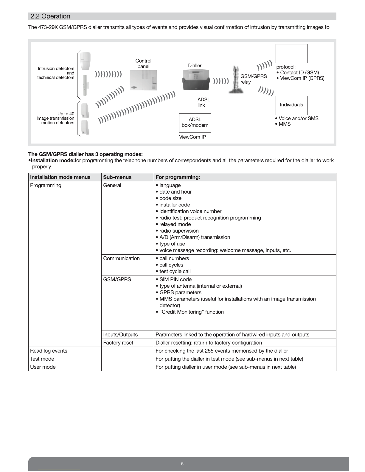
Connecting the 910-21X mains adapter for:
• transmitting an alarm system command,
• an IP/Ethernet connection.
Jack connector for connecting the 910-21X adapter on the dialler side. Connect
the 910-21X adapter to a protected and isolatable 230 V-50 Hz (16 A) mains
socket. Make sure the socket is easily accessible
and close to the telephone dialler.
OR3. Position the BATLI23 power pack on
the guide rails. Slide the pack along
the rails until it is locked into
position.
IMPORTANT:
if the adapter (910-21X) is connected, it is
useless to connect also the BATLI23 power pack,
because this one would never be used (in case of mains
absence, the device would be powered by the
emergency rechargeable battery).). However, connecting
the BATLI23 power pack would not cause electrical
damages to the device.
To switch back to the BATLI23 power pack as the main power supply, you must:
• disconnect all sources of power for several seconds (BATLI23 power pack, 910-21X mains adapter and rechargeable battery
908-21X),
• connect the rechargeable battery 908-21X then BATLI23 power pack.
IMPORTANT: during this stage, you must choose the dialler's main power supply (BATLI23 power pack or 910-21X mains adapter).
Once the 910-21X mains type power supply is connected, the dialler validates this as the main source of power and will no longer
authorise use of the BATLI23 power pack.
910-21X external
power supply:
5 V DC – 1A/5 W
Electric shock
hazard
1. Insert the SIM card.
Insert the SIM card in the
slot making sure it is the
right way round.
IMPORTANT
• Mini-UICC SIM Cards
MUST NOT BE
INSERTED directly into
the SIM card slot of the
GSM transmitter.
• A Mini-UICC SIM card
must be inserted in an adaptor (not provided)
before insertion into the GSM SIM card slot.
Adapter

10
4.1 Essential programming (language, date/hour, size of codes and installer code)
4. Main programming operations
How to use the keys on the keypad
• Pressing (all keys) briefly: this is the most usual way to press keys in order to browse through the various menus and sub-menus, or
validate/cancel a parameter or digit.
• Pressing and holding the (OK) key: validates choices.
• Pressing and holding the (C) key: exits a menu without validating choices.
During programming, the dialler switches to standby mode and the display goes blank if no key is pressed for 2 min. The screen will
light up again when any key is briefly pressed.
1. When the dialler is first powered it is in
installation mode and displays:
4. Perform the following essential programming operations as shown below:
2. Select the language using the Land M
keys and then press OK.
3. Select the date and hour using
the Land Mkeys
and then press OK.
Bonjour
473-29X
Langue
Francais
Language
English
General
Date/hour
then
Programming Display Actions to be performed
to be performed
Programming Select the Date/Hour menu using the Land Mkeys,
the date and hour then press OK
Programming the date using keys 0 to 9.
The Land Mkeys can be used to place the cursor on the digit to be modified
Programming the hour using keys 0 to 9.
The Land Mkeys can be used to place the cursor on the digit to be modified
Programming Select the Code size menu using the Land Mkeys,
the installer code then press OK
Default installer
code: 1111
Default master The installer code size and master code size is 4 by default.
code: 0000 Press key 5 or 6 and then OK to change the size.
NB: the code size can only be changed when the 2 codes have their factory-set
values
Select the Install code menu using the Land Mkeys,
then press OK
Press OK
Change the installer code using keys 0 to 9.
Press OK.
General
Date/hour
Date/hour
Date
General
Code size
Date/hour
Hour
Code size
4
General
Install code
Install code
Change
Install code
1 1 1 1
Programming
General
INSTALLATION
MODE

11
For the first programming operation, you will need the PIN code
(you will find this on the subscription contract).
4.2 Programming the PIN code
• The GSM dialler is fitted with a built-in antenna for the transmission of data to the GSM network. It is possible to connect an external
antenna in order to improve the quality of GSM transmissions. Two types of antenna are available in the catalogue:
- 903-21X: 5 dB antenna mounted on a bracket,
- 904-21X: 3 dB antenna with magnetic fixing.
• Although the reception level may be greater than 10 (see chapter 12.2), the voice messages retransmitted during a telephone call
may be of poor quality depending on the installation.
4.3 Selecting the internal or external antenna
Programming Display Actions to be performed
to be performed
Programming Select the Programming menu using the Land Mkeys,
the PIN code then press OK
Select the GSM/GPRS menu using the Land Mkeys,
then press OK
Select the PIN Code menu using the Land Mkeys,
then press OK
Select Change using the Land Mkeys,
then press OK
Programming the PIN code menu using keys 0 to 9,
then press OK
Install mode
Programming
Programming
GSM/GPRS
GSM/GPRS
PIN code
PIN code
Change
PIN code
0 0 0 0
Programming Display Actions to be performed
to be performed
Selecting internal Select the Programming menu using the Land Mkeys,
or external antenna then press OK
Select the GSM/GPRS menu using the Land Mkeys,
then press OK
Select the GSM antenna set. menu using the Land Mkeys,
then press OK
Select the Internal antenna or External antenna menu using the Land Mkeys,
then press OK
Install mode
Programming
Programming
GSM/GPRS
GSM/GPRS
GSM antenna set.
GSM antenna set.
Internal antenna
GSM antenna set.
External antenna
IMPORTANT: to prevent any electrical damage when adding an external antenna, make sure the antenna is installed inside the home.
or
Programming
GSM/GPRS
Programming
GSM/GPRS
INSTALLATION
MODE

12
5.1 Programming the dialler to recognise the control panel
5. Recognition programming WITH an alarm control panel
If the control panel has already been programmed to recognise another separate dialler (PSTN phone or video communicator),
it will not at first be possible to add a GSM telephone dialler.
A GSM dialler can be installed on top of a PSTN phone and/or video communicator if the control panel is a 1.12.0 version or later.
Enter on the control panel keypad to check.
503
master code
(by default: 0000)
1. Put the system in installation mode
To do this, ask the user to enter the following on the control panel or control interface keypad:
then enter 3
2
2. Put the GSM dialler in recognition programming mode
master code
(by default: 0000)
installer code
(by default: 1111)
Programming Display Actions to be performed
to be performedr
Putting the GSM Select the Programming menu using the Land Mkeys,
dialler in recognition then press OK
Programme mode
Select the General menu using the Land Mkeys,
then press OK
Select the Radio test menu using the Land Mkeys,
then press OK
Select Recog prog then press OK
Move on to step 3
Install mode
Programming
Programming
General
General
Radio test
Radio test
Recog prog
Recog prog
General
Radio test
INSTALLATION
MODE
If the control panel has already been programmed to recognise another separate dialler (PSTN phone or video
communicator)
A. Delete the PSTN or video phone communicator:
Dial the following sequence on the control panel keypad or the control interface remote keypad:
1
5
4
9
1
B. Dial the following sequence on the PSTN or video phone communicator
C. Proceed as follows to re-programme the control panel to recognise the PSTN or video phone communicator:
)
))
)
)
then
10 sec. max.
Press *then # on
the communicator
keypad
Press and hold *
until the communicator
responds
The communicator issues
a long beep to validate control
panel recognition programming.
The control panel issues a voice
message to confirm communicator
recognition programming.
“beeeep” “beep, device n° transmitter” IMPORTANT: The
communicator indicates an
error by emitting 3 short
beeps. When this happens,
recognition programming
should be carried out again
from the start.

13
“beep, dialler”
Recog prog
IIIIII
3. Press then on the dialler.
4. Press and hold on the control panel keypad.
The control panel confirms recognition programming by issuing
the voice message “beep, dialler” and the dialler confirms by issuing
the voice message “beep, control panel”.
then
“beep, control panel”
5.2 Programming the control panel to recognise the image transmission detectors
1to
10 s max.
Press *then #
on the keypad
built into the
control panel.
Press and hold the “test”
button on the motion
detector until the control
panel responds.
The control panel waits
for you to select the group:
1 to 8. Use the control
panel keypad to make the
selection.
Select an immediate time
delay.
Use the control panel keypad
to make the selection.
The control panel
issues a voice
message to
confirm detector
recognition
programming.
“time delay?”
The red LED
flashes twice
for 2 s.
8
)
)
)
)
)
“beep, detector
X, group?”
• An immediate time delay must be programmed to record an image sequence as soon as intrusion occurs.
• The control panel issues 3 short beeps to indicate a programming error. When this occurs, programming should be performed again
from the start.
“beeeep, beep,
detector X,
group Y,
immediate”
IMPORTANT: the recognition programming procedure differs according to the control panel software version.
To know which software version you have,
use the control panel keypad to check it by entering: 503
5.2.1 Recognition programming with a control panel fitted with software version 1.15.6 and later
master code (by default: 0000)
then
The detector must be programmed to be recognised by the control panel first and then by the dialler.
0

14
Checking recognition programming
When checking that devices have been programmed for recognition,
the control panel issues the following voice messages in the order given:
• control devices,
• intrusion detectors,
• sirens.
To check all devices programmed,
press the following keys on the control panel: 1 1
Example:
“beep, control device 1,
beep, control device 2,
beep, detector 1, group 2, immediate,
beep, siren 1”
INSTALLATION
MODE
1
then to
10 s max.
Press *then #
on the keypad
built into the
control panel
Press and hold the “test”
button on the motion
detector until the control
panel responds
The control panel waits
for you to select the group:
1 to 8. Use the control
panel keypad to make the
selection.
Select an immediate time
delay.
Use the control panel keypad
to make the selection.
The control panel
issues a voice
message to confirm
detector recognition
programming
“time delay?”
8
)
)
)
)
)
“beep, detector
X, group?” “beeeep, beep,
detector X,
group Y,
immediate”
5.2.2 Recognition programming with a control panel fitted with a software version below to 1.15.6
To perform recognition programming, the following steps must be followed:
• Programming the control panel to recognise the detector
• Programming the detector to recognise the control panel
Press and hold the test
button on the detector until
the control panel responds
Press and hold *on the
control panel until the detector
LED lights up for 2 s.
The red LED on the detector
lights up for 2 s to confirm
recognition programming.
)
)
)
)
)
“beep, detector
X, group?”
10 s max.2 s min.
0

5.4 Testing the radio link between the dialler and the image transmission detector(s)
For each image transmission detector, we recommend you check the radio link with the GSM/GPRS dialler (we advise you to move away
slightly, placing the product at least 2 m from the GSM/GPRS dialler). For lasting reliability, it is essential to carefully check each radio link,
as explained below, once all the products have been installed:
1. Dialler in installation mode 2. Briefly press the test button on the
detector.
3. The dialler performs the test:
• long beep, test OK,
• 3 short beeps, test not OK.
15 s max sliding
bar graph
Install mode
Programming
Test Com HD
IIIIIIIIIII
5.3 Programming the dialler to recognise image transmission motion detectors
IMPORTANT
• Both the dialler (for image transmission) and the control panel (for intrusion event transmission) must be programmed to recognise the
image transmission motion detectors.
• The dialler can only be programmed to recognise the image transmission motion detectors (up to 40) if it has already been programmed
to recognise the control panel.
• The dialler automatically allocates a number during recognition programming. Consequently, the same detector can be recognised by
the control panel as number 10 and recognised by the GSM dialler as number 6.
Programming Display Actions to be performed
to be performed
Putting the GSM Select the Programming menu using the Land Mkeys,
dialler in recognition then press OK
programming mode
Select the General menu using the Land Mkeys,
then press OK
Select the Radio test menu using the Land Mkeys,
then press OK
Select Recog prog programming then press OK
Press then on the dialler
Press and hold the test button on the detector until the dialler responds with
“Detector n° X” (X = 1 to 40)
Install mode
Programming
Programming
General
General
Radio test
Radio test
Recog prog
Recog prog
IIIIII
Recog prog
“Detector n° X”
IMPORTANT
• If an error occurs during the recognition programming, the transmitter beeps 3 times. When this occurs, programming should be
performed again from the start.
• In case of repeated failure, please proceed as follows:
1. power off the control panel and the radio repeater relay(s) if any in the installation,
2. recognition programming should be carried out again from the start.
The red LED flashes
twice for 2 s.
General
Radio test
IMPORTANT: if the radio link has not been established (no “Test Com HD” display), all the recognition programming must be performed
again.
15
INSTALLATION
MODE

16
Programming Display Actions to be performed
to be performed
Putting the GSM Select the Programming menu using the Land Mkeys,
dialler in recognition then press OK
programming mode
Select the General menu using the Land Mkeys,
then press OK
Select the Radio test menu using the Land Mkeys,
then press OK
Select Recog prog then press OK
Press then on the dialler
Press and hold the “Test” button on the external universal transmitter or the “0”
programming key on the smoke detector
until the dialler responds
with “Detector n° X” (X = 1 to 40)
Install mode
Programming
Programming
General
General
Radio test
Radio test
Recog prog
Recog prog
Recog prog
IIIIII
Programming Display Actions to be performed
to be performed
Putting the GSM Select the Programming menu using the Land Mkeys,
dialler in recognition then press OK
programming mode
Select the General menu using the Land Mkeys,
then press OK
Select the Radio test menu using the Land Mkeys,
then press OK
Select Recog prog then press OK
Press then on the dialler
Press and hold the alarm pendant or the remote control OFF button until the dialler
responds with “Control device n° X”
(X = 1 to 10)
Install mode
Programming
Programming
General
General
Radio test
Radio test
Recog prog
Recog prog
IIIIII
Recog prog
6.1 Programming the dialler to recognise technical and fire detectors
6.2 Programming the dialler to recognise control devices (alarm pendant)
6. Recognition programming WITHOUT an alarm control panel
Checking recognition programming
• Press the detector test button or the “0”
programming key to check recognition
programming.
• Press the alarm pendant to check
recognition programming.
• Press the alarm button on the remote
control to check recognition programming.
IMPORTANT: the OFF button is used for remote control recognition programming. However, the Alarm button is used to check recognition programming.
“Control device n° X” “Control device n° X”
“Control device n° X”
General
Radio test
General
Radio test
INSTALLATION
MODE
“Detector n° X”
“Detector X”

17
7. Programming for calls to individual correspondents
INSTALLATION
MODE
Procedure for a voice call to an individual
At correspondent’s
home
At the user’s
home
GSM
telephone
dialler
alarm
triggered
number
dialled
phone
rings
Acknowledgement
and termination
60-second listen-in and
speak-out/talk-back period
(repeatable up to 4 times)
(1)
dialler hangs
up
long beep
if call
acknowledged
press “0”
to
acknowledge
pre-recorded
alarm
message
identification
message
identification
n°
phone
answered
Call cycle repeated
(up to 5 times max)
until call is acknowledged
(1) A personalised message can be recorded for hardwired inputs 1 to 4 and groups 1 to 8.
Programming Display Actions to be performed
to be performed
Programming Select the Programming menu using the Land Mkeys,
telephone numbers then press OK
Select the Communication menu using the Land Mkeys,
then press OK
Select the Call number prog menu using the Land Mkeys,
then press OK
Select the number to be programmed from 1 to 8 using the Land Mkeys,
then press OK
Select Change using the Land Mkeys,
then press OK
Select the Voice or SMS menu using the Land Mkeys,
then press OK
N.B. only valid with a voice SIM card
Select with or without listen-in period using the Land Mkeys,
then press OK
Select with or without call-back using the Land Mkeys,
then press OK
Programming your correspondent’s telephone number.
Add 00 in front of the number for calls abroad.
Install mode
Programming
Programming
Communication
Communication
Call number prog
Call number prog
# 1
# 1
Change
Protocol
Voice
Voice
Listen-in OFF
Voice
Call back OFF
Enter 20 c max
----------------
7.1 Programming call numbers and transmission type
(1)
(2)
(1) The initial listen-in period is 60 s. During the listen-in period, you can press the # key to repeat listen-in for another period of 60 s.
Listen-in can be repeated up to 4 times (5 min max).
(2) With call-back means with a confirmation call. The correspondent can call the dialler back within the 90 s following acknowledgement.
During this 90 s period, the correspondent can “request” either a listen-in period, or an intercom period, or transmit an alarm system command.
Programming
Communication

18
Programming Display Actions to be performed
to be performed
Programming Select the Programming menu using the Land Mkeys,
event type then press OK
Select the Communication menu using the Land Mkeys,
then press OK
Select the Call cycle menu using the Land Mkeys,
then press OK
Select the call cycle to be programmed (cycle 1, 2 or 3) using the Land Mkeys,
then press OK
Select the event type(s) to be not transmitted for each call cycle selected by pressing
the group n°, then press OK (see table page 6: Type of events transmitted)
Install mode
Programming
Programming
Communication
Communication
Call cycle
Call cycle
Cycle 1
Events (5 max)
1 2 3 4 5
7.2 Programming the type of events transmitted
Makes it possible
to allocate alarm
groups to the call
cycle. By default,
the 3 call cycles
are programmed
to transmit all types
of events.
Programming
Communication
7.3 Programming a periodic call to an individual correspondent
Programming a Periodic callallows an individual correspondent to receive an SMS telling them that the dialler is operational. For
this to be possible, at least one of the telephone numbers needs to be programmed to receive an SMS call.
Programming Display Actions to be performed
to be performed
Programming Select the Programming menu using the Land Mkeys,
a test cycle call then press OK
Select the Communication menu using the Land Mkeys,
then press OK
Select the Periodic call menu using the Land Mkeys,
then press OK
Select Change using the Land Mkeys,
then press OK
Programming the time at which the SMS must be transmitted using keys 0 to 9,
then press OK
Programming the Periodic callperiodicity in Days, Hours or Minutes, then press OK
Examples:
• for a monthly call, select Day and enter 30
• for a weekly call, select Day and enter 7
• for a call every 12 hours, select Hour and enter 12.
Install mode
Programming
Programming
Communication
Communication
Periodic call
Periodic call
Change
1 call:HHmm
00:00
Period
Day
Period
Hour
Period
Minutes
IMPORTANT: SMS calls generated for test cycle calls use up credit and impact product battery life.
Programming
Communication
INSTALLATION
MODE

19
Once enabled, this function is used for transmitting all Arm and Disarm commands to numbers programmed
to receive SMS only. If no number has been programmed to receive SMS, Arm/Disarm
commands will not be transmitted.
7.4 Programming Arm/Disarm transmission via SMS
Programming Display Actions to be performed
to be performed
Programming Select the Arm/disarm trans menu using the Land Mkeys,
Arm/Disarm then press OK
transmission
This function is disabled by default
Select the Enabled line then press OK to validate
General
Arm/disarm trans
Arm/disarm trans
Disabled
Arm/disarm trans
Enabled
The voice welcome message allows correspondents to identify the dialler having triggered the alarm.
• To listen to the recording:
7.5 Recording the personalised welcome voice message
Programming Display Actions to be performed
to be performed
Recording the voice Select the Recording mess. menu using the Land Mkeys,
welcome message then press OK
Select the Welcome message menu using the Land Mkeys,
then press OK
Select Change to start recording the voice message (10 s max).
Once the voice message has been spoken out loud, press OK to validate the recording.
General
Recording mess.
Recording mess.
Welcome message
Welcome message
Change
Welcome message
Playing back REC
Example:
“You are connected
to the alarm system
of Mr Jacob,
6 Strawberry Lane,
Liverpool”
The voice ID number lets correspondent(s) identify the dialler behind the call.
This identification number is useful when SMS messages are transmitted. When voice messages are
transmitted, this voice identification number is replaced by the pre-recorded personalised greeting message.
To delete the voice ID number and return to the default value 99:
OK OK
7.6 Programming the SMS voice ID number
Programming Display Actions to be performed
to be performed
Programming voice Select the Voice ID menu using the Land Mkeys,
identification then press OK
number
Select Change using the Land Mkeys,
then press OK
Modify the voice identification number using keys 0 to 9.
Press OK.
NB: 1 to 8 numbers can be programmed
General
Voice ID
Voice ID
Change
Voice ID
9 9
Voice ID
Delete
Delete
Are you sure?
• To delete the recording:
OKOK OK
Welcome message
Delete
Delete
Are you sure?
“welcome voice message”
General
Arm/disarm trans
General
Recording mess.
General
Voice ID
INSTALLATION
MODE

20
7.7 Programming linked to image transmission detectors
To be able to transmit images in MMS format, several parameters specific to each GSM operator used must be programmed (1).
INSTALLATION
MODE
(1) These operator parameters may be modified at any time without Daitem being informed.
DAITEM shall not be held liable for the direct or indirect consequences of technical and contractual modifications made by the mobile phone network
operator chosen by the customer.
Keys Character in order of display
1.,@:/1
2ABC2
3DEF3
4GHI4
5JKL5
6MNO6
7PQRS7
8TUV8
9WXYZ9
0+-0
]
For example, to write “orange”:
Press 6 key 3 times
Press 7 key 3 times
Press 2 key once
Press 6 key 2 times
Press 4 key 4 times
Press 3 key 2 times
Wait 2 seconds
after each character
or press OK
}
• For images to be transmitted, the system correspondent number (n°9) must be programmed.
This is the only number able to receive the MMS images transmitted by the dialler.
IMPORTANT
• When used with GSM-GPRS transmission dialler associated with image transmission motion detectors, the transmission dialler requires
a SIM card with compatible MMS.
• Daitem cannot guarantee the time required to transmit an MMS to an individual correspondent.
• Consulting the dialler events log only allows the user to check whether an MMS has been acknowledged by the operator’s server.
• Daitem has no control over the time required for transmission between the operator’s server and the correspondent.
Programming Display Actions to be performed
to be performed
Programming Select the Programming menu using the Land Mkeys,
telephone numbers then press OK
Select the Communication menu using the Land Mkeys,
then press OK
Select the Call number prog menu using the Land Mkeys,
then press OK
Select System N° using the Land Mkeys,
then press OK
Select Change using the Land Mkeys,
then press OK
Programming your correspondent’s telephone number
Add 00 in front of the number for calls abroad
Install mode
Programming
Programming
Communication
Communication
Call number prog
Call number prog
System N°
System N°
Change
Enter 20 c max
----------------
Programming
Communication
Operators APN Login Password MMS Server MMS Port MMS URL
Orange orange.acte orange orange 192.168.010.200 8080 http://mms.orange.fr
SFR mmssfr - - 010.151.000.001 8080 http://mms1
Other 8080
Table of contents
Other DAITEM Security System manuals

DAITEM
DAITEM SH602AX User manual

DAITEM
DAITEM SH402AX User manual

DAITEM
DAITEM SH511AX User manual

DAITEM
DAITEM Espace range User manual

DAITEM
DAITEM SH401AX User manual

DAITEM
DAITEM SH146AX User manual

DAITEM
DAITEM SH426AX User manual

DAITEM
DAITEM MD500 Operation and maintenance manual

DAITEM
DAITEM SH423AX User manual

DAITEM
DAITEM DP8406 User manual