PSV groupe DRC114 User manual

1
F
FL
LO
OO
OR
R
S
ST
TA
AN
ND
DI
IN
NG
G
M
MI
IN
NC
CE
ER
R
D
DR
RC
C1
11
14
4
U
Us
se
er
r
G
Gu
ui
id
de
e
Usine du berre au Loup –RD147 –BP20 –95420 Genainville –France
Marques, brevets et modèles déposés France et étranger. R.C.S. Pontoise B 642 033443
« Original manual »

2
Certificate of Conformity to rules of the European Community
The manufacturer hereby GROUPE PSV, BP20 95420 GENAINVILLE
NEW EQUIPMENT COVERED BY FOLLOWING DIRECTIVES
MACHINE 2006 / 42 / CE
CEM 2014 / 30 /UE
BT 2014 / 35 / UE
MODELE : TRADITIONAL MINCER
TYPE : DRC114CS
SERIAL NUMBER :
M. Dominique VILLA
CEO

3
TABLE OF CONTENTS
1/ INTRODUCTION AND NORMALISATION ………………… p.4
2/ INSTALLATION AND ELECTRICAL CONNECTION …… p.5
3/ CHARACTERISTICS AND TECHNICAL SHEET………. p.6
4/ DESCRIPTION ……………………………………………... p.8
A/ INSTALLING THE BODY ………………………………… p.8
B/ PLATES AND KNIVES MOUNTING ………..……… p.9
2/ SYSTEM WITH 3 CUTTING ELEMENTS……………… p.10
3/ SYSTEM WITH 5 CUTTING ELEMENTS……………. p.11
C/ PRECAUTIONS………………………………………. p.12
1/ MOUNTING & MAINTENANCE OF UNGER SYSTEM p.12
2/ UTILISATION DES BOUTONS DE COMMANDE p.13
3/ PRODUCT PUSHER USING ……………………………. p.14
5/ MAINTENANCE…………………………………………........ p.15
A/ CLEANNING OF THE MACHINE…. ..……………….. p.15
B/ PRELIMINARY CLEANNING ………………………… p.15
C/ DISINFECTION…………………. ……………………. p.15
D/ RINSE… …………………………………………………. p.16
E/ MAINTENANCE …………………………………………... p.16
6/ WARNING…….…………………………………………… p.17
7/ ACCESSORIES ……………………………………………… p.17
8/ AFTER SALES SERVICE ………………………………….. p.17
9/ WARRANTY CONDITIONS…. …………………………… p.18
10/ NOMENCLATURE DRC 114………………………….. p.19/20
11/ EXPLODED VIEW DRC 114 …………………………... p.21/22/23/24
12/ ELECTRICAL SCHEME …………………………………. p. 25

4
1/ INTRODUCTION
The mincer DRC 114 can mince all kinds of meat for the production of
hamburgers, meatballs, sausage…
The mincer can be equipped with 3 or 5 cutting elements UNGER.
(See on page 10/11)
The mincer 114 is equipped of one or two knife double side with removable blades.
NORMALISATION
These devices meet the requirements of the decrees and safety standards.
General hygiene and safety laid down in Articles 84 to R233-R233-106, introduced
in the Labour Decree No. 80543 of July 15, 1980.
French standard NF U66-062, Machine chopping meat, integrated
prevention.
The control devices and signage, exhibit a degree of protection IP54 as defined in
standard NF 20-010.
All devices present a degree of protection IP245.
Continuous sound pressure level equivalent to the Workstation measured according
to standard NF S31 124 P <70 dB (A) empty and loaded
The hand-protection plate is mandatory and should never be disconnected from
the board.

5
2/ INSTALLATION
Place the machine on a stable and solid floor
ELECTRICAL CONNECTION
Electrical plug in must be preformed by qualified personnel and be conduced in
compliance with safety standards.
The line of the power supply must be carried out using a cable section adapted to the
power of the machine and must include three phase conductors and a grounding
conductor (voltage machine 400v, 50 Hz) or two phase conductors and a grounding
conductor (voltage machine 230v, 50 Hz) .
Electrical plug in must be protected by a circuit-breaker.

6
3/ CHARACTERISTICS
TECHNICAL SHEET DRC 114
TECHNICAL CHARACTERISTICS
DRC 114
Dimensions
1000 x 760 x 1250
Weight
129 kg
Packing dimensions
1200 X 800 X 1350
Débit théorique
900 Kg/h
Motor
5,5 CV / 4,1 KW
Tension
3 PHASES - 400v - 50 HZ
Gear box
PSV gear box
Cutting system
3 or 5 cutting elements UNGER
Standard equipment
1 knife, 1 plate Ø5, 1plate / knife

7
4/ DESCRIPTION
A/ BODY MOUNTING
Rotate the safety guard to place the body
Place the body in front of the machine
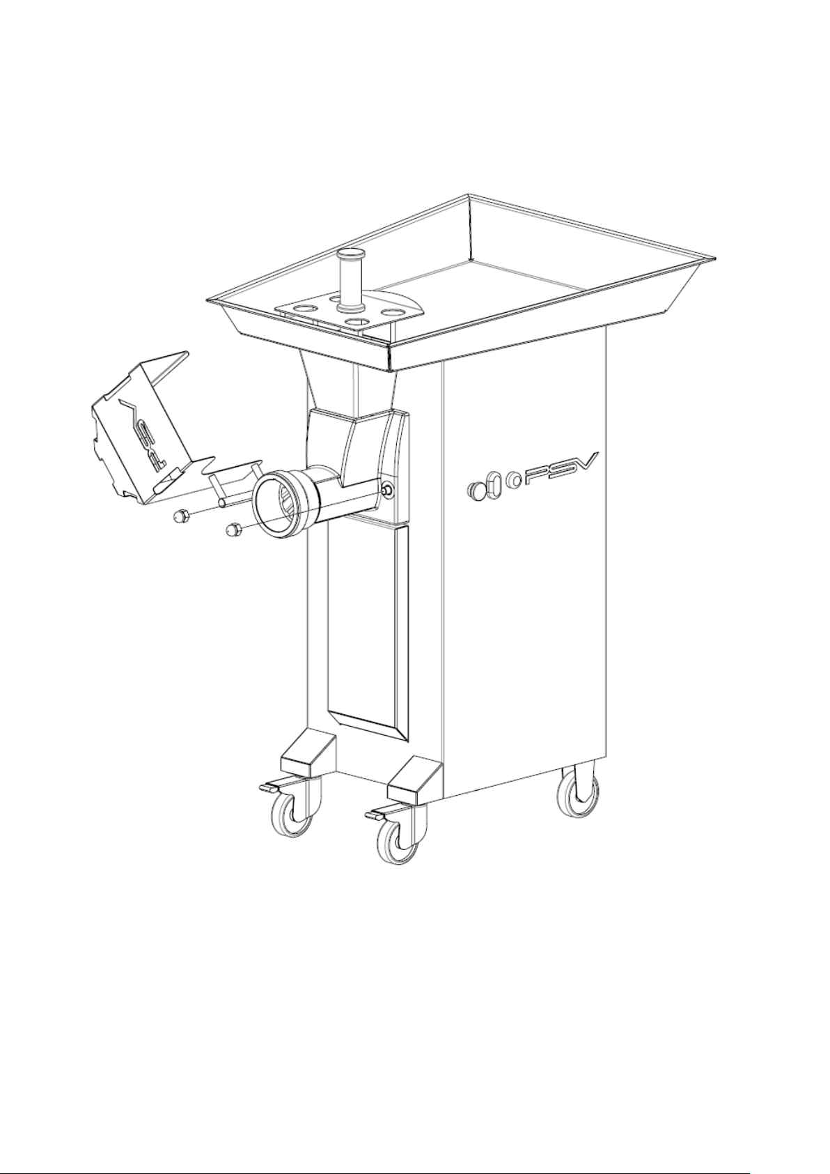
8
Fit the body in its seats (two blots through).

9
Tighten the two clamp handles setting the body on the machine
Make sure that the body is properly applied against the front

10
B/ MOUNTING PLATES AND KNIVES
1/ 3 CUTTING ELEMENTS SYSTEM (UNGER).
NOTE : DISCONNECT THE MACHINE OF THE ELECTRICAL RETE FOR THE
FOLLOWING OPERATIONS :
A- Insert the helix (2) inside the body (1) with a slight twisting motion for a good
engagement with the hex output shaft engine.
B- Mount the cutting plate (3).
C- Mount the knife (4).
D- Mout the plate (5).
E-Mount the ring (6).
F-Mount the nut (7).
IMPORTANT :
The mounting must be done in the order announced.
Do not mount the both body / helix and the cutting system in one time.
The mounting must be done following the steps.

11
2/ 5 ELEMENTS CUTTING SYSTEM (UNGER).
NOTE : DISCONNECT THE MACHINE OF THE ELECTRICAL RETE FOR THE
FOLLOWING OPERATIONS :
A- insert the helix (2) inside the body (1) with a slight twisting motion for a good
engagement with the hex output shaft engine.
B- mount the plate/knife (3).
C- mount the knife (4).
D- mount the plate (5).
E- mount the knife (6).
F- mount the plate (7).
G- mount the ring (8).
H- mount the nut (9).
IMPORTANT :
The mounting must be done in the order announced.
Do not mount the both body / helix and the cutting system in one time.
The mounting must be done following the steps.
12
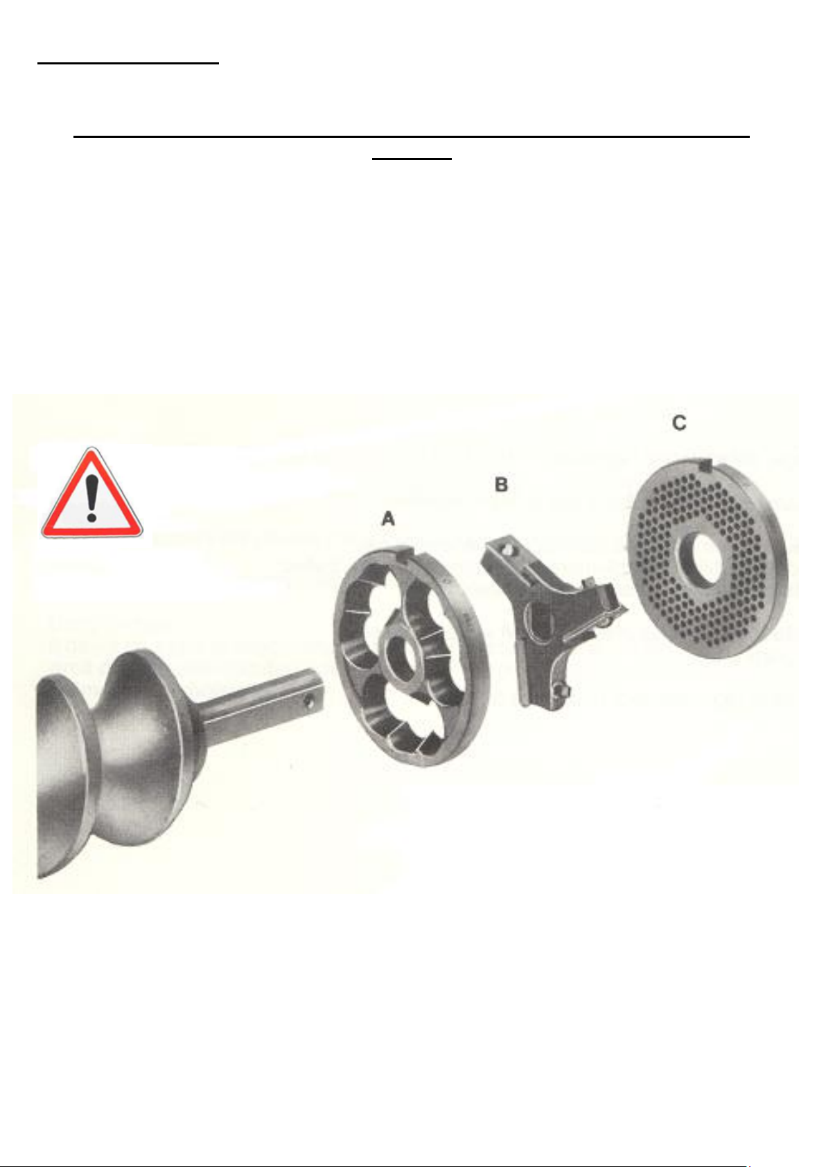
C/ PRECAUTIONS
1/ PRECAUTIONS FOR THE MOUNTING AND MAINTENANCE OF UNGER
SYSTEM
Make sure that the system is mounted as shown below. Improper installation,
including upside down, causes breakage of plates and knives.
The plate knife must be perfectly aginst the face of the body.
The nut stainless steel machine should not be tightened significantly.
Change the blades before they are flush with the branches of knives.
To surface plates from wear. Plates prevent waste a perfect fit and cause rapid wear
of blades.
A- PLATE KNIFE
B- DOUBLE FACE KNIFE (shoulder outlet plate side)
C- HOLES PLATE

13
2/ USING THE PANEL
Pushing the GREEN button, the machine starts. The rotation of the
feed screw must be done in unclock sense.
The machine stops by pushing the RED button.
If the machine is blocked, push the BLACK button once.
The emergency stop must be used to stop the machine in case of
emergency. Using this button, it must be unlocked to restart the machine.
ON BUTTON
OFF BUTTON
REVERT
BUTTON
EMERGENCY
STOP
14
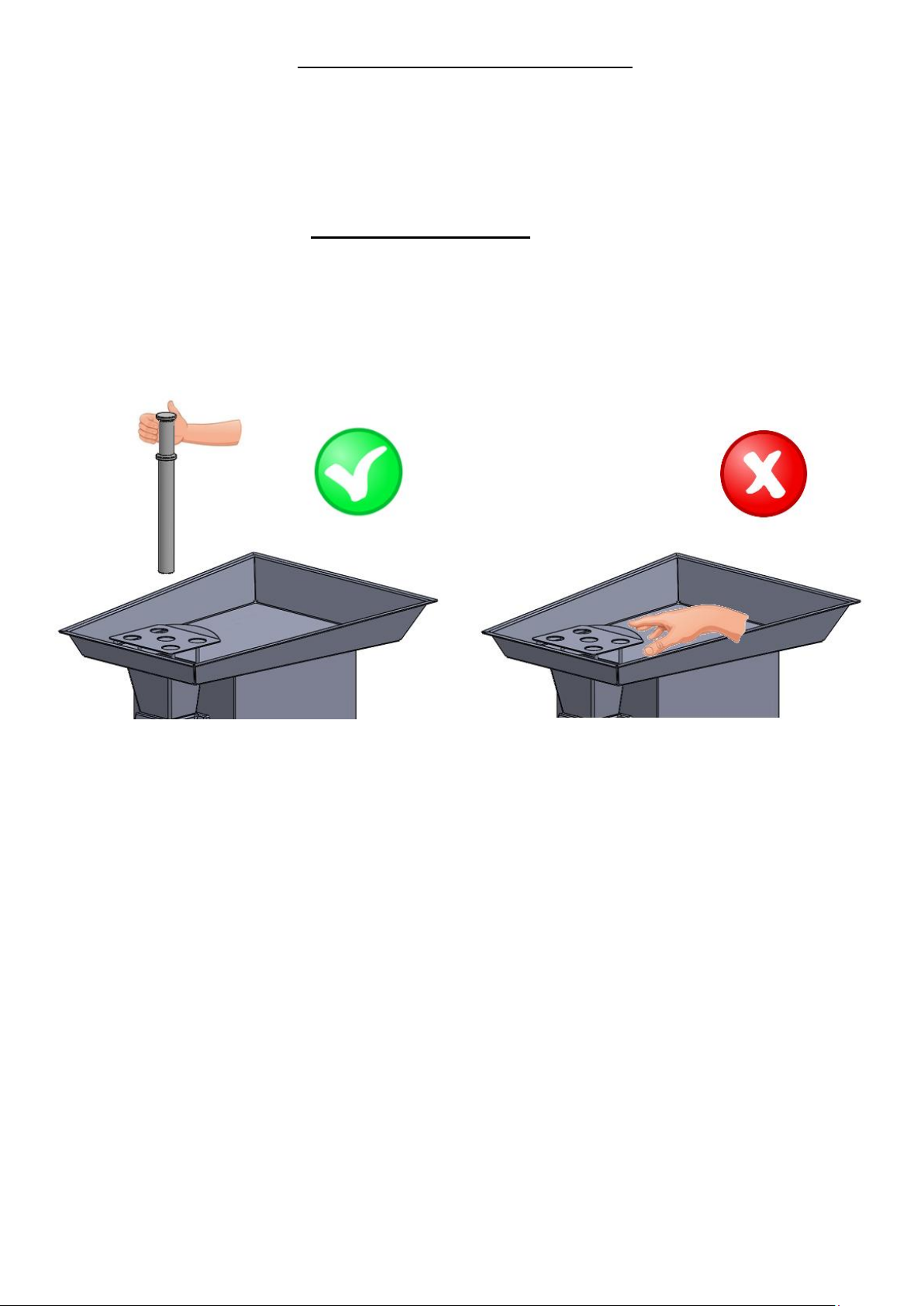
3/ USING THE PLASTIC FEEDER
The machine is delivered with a plastic feeder to push the meet in the feed screw.
Using the plastic feeder is extremely important, it is strictly forbidden to us the
hand to avoid any failures.

15
5/ MAINTENANCE
DISCONNECT BEFORE ANY INTERVENTION
A/ CLEANING OF THE MACHINE :
For obvious hygiene reasons, the machines for mince meat need to be cleaned often
and correctly. Machines must be maintained in perfect conditions, cleaned,
dismounted, disinfected two times per day.
For cutting elements cleaning, it is necessary to dismount the whole body/helix and
the cutting element in the same time to avoid any failures (and following the
standard NF EN 12331:2013).
We recommend the use of detergents and disinfecting products.
B/ PRELIMINARY CLEANING :
Remove visible dirt by brushing (body, feed screw, nut, plates and knives).
C/ DISINFECTION :
Immerse all removable parts in a bath of warm water (T° 45 à 55°C), with an
appropriate detergent.
For the meat plate and the body wash in warm water with the same detergent.
D/ RINCE :
Rinse the removable parts
Rinse the plate and the body

16
Do not immerse the device
Do not clean with high pressure jet
The brushes used must be cleaned with a detergent solution.
The chopper’s body does not require special maintenance. Just use a towel or
disposable paper moistened
Avoid using abrasive cleaners that will damage the steel. Sponges are
prohibited.
E/ MAINTENANCE :
Lock system must be controlled daily.

17
6/ WARNING
SECURITY PARTS :
En aucun cas la plaque protège-main située sur le plateau doit être déformée et à
fortiori enlevée ou dessoudée.
PROTECTION AGAINST THE RISKS OF FAILURES CAUSED BY
KNIVES :
There is a serious risk when the operator can move the fingers through the plates as
the knife rotates in contact with it.
When the holes have a diameter less than 4mm, the risk of introduction of the
fingers does not exist (CF NF E 09-010). It is the same for diameters between 4 and
8mm included, provided that the plate has a thickness of 5mm.
For holes diameters greater than 8mm or specially shaped opening (in beans for
example), it is necessary to develop a device which prevents access to the
dangerous part.
The safety guard in front of the machine has been developed for that case, in
conformity with EN 12331 : 2013 standard.
7/ ACCESSORIES
The device is delivered with a pestle in food and a 24 key for the body clamping.
8/ AFTER SALES SERVICE
After sales service must be done by our distributor :
Our distributor will take care of the machine’s installation and possible
restoration of your device
Our distributor will answer your enquiry of spare parts and accessories.

18
9/ WARRANTY CONDITIONS
En tant que fabricant, nous garantissons notre matériel un an contre tout vice de
fabrication, la facture faisant office de bon de garantie.
As a manufacturer, we guarantee one year for any manufacturing defect, the
invoice acting as a warranty.
IMPORTANT :
Electricals and electronics are excluded from the warranty.
Warranty limits :
The warranty applies only to the purchaser and not to third parties to which
the material could be resold.
Our guarantee is limited to replacement or repair free of parts found defective by us.
In this case, the material is returned to us prepaid.
The port and the workforce are in all cases be borne by our distributor.
All comments and not misuse by special instructions, changes, modifications, or
repairs outside the workshop of an authorized dealer, and the lack of identification
plate, resulting in the cancellation of the guarantee.

19
10/ NOMENCLATURE
NOMENCLATURE DRC 114 -
DESCRIPTIONS
REFERENCE
QTY / 114
PART
NUMBER
PLASTIC FEEDER
1
1
921C
STAINLESS STEEL PLATE + HAND PROTECT
2
1
993
STAINLESS STEEL NUT
3
1
412
COMPENSATION RING
4
1
391
PLATE 114
5
1
D114/5MM
KNIFE 114
6
1
CTX_D114
PLATE / KNIFE 114
7
1
D114/00
KNIFE HOLDER 114
8
1
389
STAINLESS STEEL FEED SCREW114
9
1
992
CLAVETTE PLAQUE DE COUPE
10
1
777
VIS TFB FIXATION CLAVETTE
11
1
ECROU BORGNE FORME HAUTE
12
2
ZVIS921
STAINLESS STEEL BODY
13
1
991
BODY RING
14
2
957 BIS
CHOPPER
15
1
993
VIS CHC FIXATION COUVERCLE RÉDUCTEUR
16
8
LIP SEAL TYPE AS
17
1
997A
GEAR BOX COVER
18
1
971
ANNEAU ÉLASTIQUE POUR ALÉSAGE
19
1
998
NEEDLES BEARING
20
1
996E
BORRELLY WASHER
21
1
ZVIS173
BEARING STOP WASHER LS
22
1
996D
NEEDLES CAGE AXIAL AXK
23
1
996C
BEARING STOP WASHER AS
24
1
996B
ROUE AVEC ARBRE + PIGNON INTERMEDIAIRE
25
1
967BIS
PLAQUE INSONORISANTE ( 1 PLAQUE DE 500 x 505 Pour 3
machines )
26
1
799
RONDELLE DE BUTÉE DE ROULEMENT AS
27
1
944
NEEDLES CAGE AXIAL AXK
28
1
946
BEARING STOP WASHER LS
29
1
945
DOUILLE A AIGUILLES HK
30
1
996A
ROULEMENTS A UNE RANGEE DE BILLES A CONTACT RADIAL
31
2
996F
PIGNON INTERMEDIAIRE
32
1
967BIS
GOUPILLE CENTRAGE REDUCTEUR
33
1
044
GEAR BOX BODY
34
1
970
JOINT D'ETANCHEITE POUR BOUCHON
35
1
BOUCHON DE REMPLISSAGE HUILE
36
1
910
LIP SEAL TYPE AS
37
1
997B
THREE PHASES MOTOR
38
1
967
GROWER WASHER
39
4
ZVIS920
VIS A TETE HEXAGONALE ENTIEREMENT FILETEE
40
4
ZVIS918
RONDELLE PLATE
41
6
ZVISI10-004
RONDELLE EVENTAIL EXTERIEUR
42
4
ZVIS083

20
VIS THEF FIXATION REDUCTEUR
43
2
ZVIS007
HEXAGONAL NUT
44
2
ZVIS025
GEAR FIXATION SCREW
45
2
ZVIS919
ION/OFF BUTTON + AUXILIARY BLOCK
46
1
459-2/459-1
ON/OFF BUTTON + CAP + AUXILIARY BLOCK
47
1
936/936A/937B
BOUTON IMPULSION ARRIERE + CAP + AUXILIARY BLOCK
48
1
937D/935B/93C
INSERT TETE CYLINDRIQUE
49
4
VIT020
RONDELLE PLATE
50
4
ZVIS047
RONDELLE EVENTAIL EXTERIEUR
51
4
ZVIS060
VIS A TETE HEXAGONALE ENTIEREMENT FILETEE THEF
52
4
ZVIS092
INSERT TETE CYLINDRIQUE
53
10
Z/105
TOLE SUPPORT BOITIER
54
1
993
INSERT TETE CYLINDRIQUE
55
2
Z/105
RONDELLE PLATE
56
2
ZVIS112
RONDELLE EVENTAIL EXTERIEUR
57
2
ZVIS029
VIS CHC FIXATION TOLE SUPPORT BOITIER
58
2
ZVIS058
ELECTRONIC BOARD
59
1
934
RONDELLE PLATE
60
4
ZVIS035
RONDELLE EVENTAIL EXTERIEUR
61
4
ZVISI10-006
VIS TRL FIXATION BOITIER
62
4
ZVIS074
TÔLE ARRIÈRE INOX
63
1
993
VIS TRL FIXATION TÔLE ARRIÈRE INOX
64
10
ZVIS099
PRESSE ETOUPE + ECROU NOIR
65
1
923
CÂBLE PREMOULE
66
1
ZCAB003
FIXED WHEEL
67
2
9009
ROULETTE PIVOTANTE
68
2
9009BIS
VIS A TETE CYLINDRIQUE A SIX PANS CREUX
69
4
GROWER WASHER
70
4
PROXIMITY CONTACT
71
1
404
CONTACT SUPPORT
72
1
VIS A TETE HEXAGONALE ENTIEREMENT FILETEE THEF
73
2
RONDELLE EVENTAIL EXTERIEUR
74
2
RONDELLE PLATE
75
2
GOUJON FIXATION CORPS
76
2
995
BAGUE DE GUIDAGE CAPOT
77
2
9013
SAFETY GUARD
78
1
993
VIS A TETE HEXAGONALE ENTIEREMENT FILETEE THEF
79
1
BUTEE PLASTIQUE DE CAPOT
80
1
9012
PLASTIC LEG
81
1
VIS TRL
82
1
ANNEAU A MONTAGE RADIAL Ø16x1,5
83
4
9018
ECROU INDESSERRABLE
84
4
AIMANT DE CONTACT
85
1
655
BUTEE TOLE
86
1
993
GREY PLASTIC STOP
87
4
9011
VIS A TETE HEXAGONALE ENTIEREMENT FILETEE THEF
88
2
VIS TF FIXATION AIMANT
89
4
CLE DE SERRAGE ECROU BORGNE ( S=24)
90
1
993
Table of contents
Other PSV groupe Kitchen Appliance manuals


