PSV groupe DRC 32 User manual
Mincer
DRC 32/98
User Guide
Usine du berre au Loup
–
RD147
–
BP20
–
95420 Genainville
–
France
Brand, patents and models registered in France and abroad R.C.S.
Pontoise B 642 033443

NEW EQUIPMENT COVERED BY THE DIRECTIVE
1. CEM 2014 / 30 / UE
2. BT 2014 / 35 / UE
- MACHINE 2006 / 42 / CE
CERTIFICATE OF COMPLIANCE rules of the European
Community.
The Manufacturer hereby PSV Groupe, BP20 95420
Genainville certifies that the new material designated below:
TRADITIONNAL MINCER
TYPE :..............
Serial number :...............
Genainville, done on .............
M. Michel PATUREL
CEO

Table of contents
1 Introduction ...................................................................................................1
2 Installation and Electrical connection ........................................................2
3 Features and specifications.........................................................................3
4 Description ....................................................................................................5
4.1 Installing the body....................................................................................5
4.2 Mouting plates and knives .......................................................................6
4.2.1 SYSTEM 2 CUTTING ELEMENTS (enterprise). .............................. 6
4.2.2 SYSTEM WITH 3 CUTTING ELEMENTS (UNGER). .......................7
4.2.3 SYSTEM WITH 5 CUTTING ELEMENTS (UNGER). .......................8
4.2.4 PRECAUTIONS FOR INSTALLATION AND MAINTENANCE..........8
5 Maintenance ..................................................................................................9
5.1 Cleanning the machine ..........................................................................10
5.2 Preliminary cleanning.............................................................................10
5.3 Disinfection.............................................................................................10
5.4 Rinse......................................................................................................10
5.5 Maintenance...........................................................................................10
6 Warning........................................................................................................11
7 Accessories.................................................................................................11
8 Customer service....................................................................................11
9 Warranty.......................................................................................................12
10 DRC 32/98 nomenclature..........................................................................13
11 Exploded scheme DRC 32/98...................................................................15
12 Electric Scheme ........................................................................................17

1 Introduction
DRC 32, DRC 98 mincers can mince all kinds of meat for
the production of hamburgers, meatballs, sausage, etc...
They can be equipped with two cutting elements version
ENTREPRISE 32 (a plate and a knife), and three or five
cutting elements version UNGER 98. (See page 9.10.11)
DRC 32 has one knife single side, self-sharpening.
DRC 98 has one or two knife double side, with
removable blades.
STANDARDS
These devices meet the requirements of the decrees and safety
standards.
General hygiene and safety laid down in Articles 84 to R233-
R233-106, introduced in the Labour Decree No. 80543 of
July 15, 1980.
French standard NF U66-062, Machine chopping
meat, integrated prevention.
The control devices and signage, exhibit a degree of protection
IP54 as defined in standard NF 20-010.
All devices present a degree of protection IP245.
Continuous sound pressure level equivalent to the
Workstation measured according to standard NF S31 124 P
<70 dB (A) empty and loaded
The hand-protection plate is mandatory and should never
be disconnected from the board.
1

2 Installation and Electrical connection
0 Position the machine on a stable and solid work surface.
0 See recommended height of sketches above.
ELECTRICAL CONNECTION
0 The electrical connection must be performed by qualified
personnel and be conducted in compliance with safety
standards in force.
0 The line of the power supply must be carried out using a
cable section adapted to the power of the machine and
must include three phase conductors and a grounding
conductor (voltage machine 400v, 50 Hz) or two phase
conductors and a grounding conductor (voltage machine
230v, 50 Hz) .
0 The power of the machine must be protected by a breaker.
2

3 Features and specifications
TECHNICAL SHEET
DRC 32 / 98
Specifications
Version 98
Version 32
Dimensions
670(L) x 425 x 505
620(L) x 425 x 505
Weight
58kg
55kg
Packing
780 x 670 x 705
780 x 670 x 705
Theorotical flom
600 kg/h
600 kg/h
Engine
3CV / 2.2 KW continuous work
3CV / 2.2 KW continuous
work
Voltage
TRI - 400v - 50 HZ /
MONO - 230V - 50HZ
TRI - 400v - 50 HZ /
MONO - 230V - 50HZ
Reducer
Reducer PSV
Reducer PSV
Cutting system
Double cut B98 SUPINOX
Simple cut N°32 SUPINOX
Standard
equipment
1 knife, 1 plate Ø5, 1cutting-
plate
1 knife, 1 plate Ø5
3

THIS MACHINE EQUIPPED WITH A SAFETY
SYSTEM ELECTROMAGNETIC, only work
when the removable plate IS IN PLACE.
4

4 Description
4.1 Installing the body
Place the body in front of the machine.
Fit the body in its seat (two bolts through).
Tighten the two clamp handles setting the body on
the machine.
Make sure the body is properly applied against the front.
5
4.2 Mouting plates and knives
NOTE : Disconnect the machine from the electricity grid
for the following:
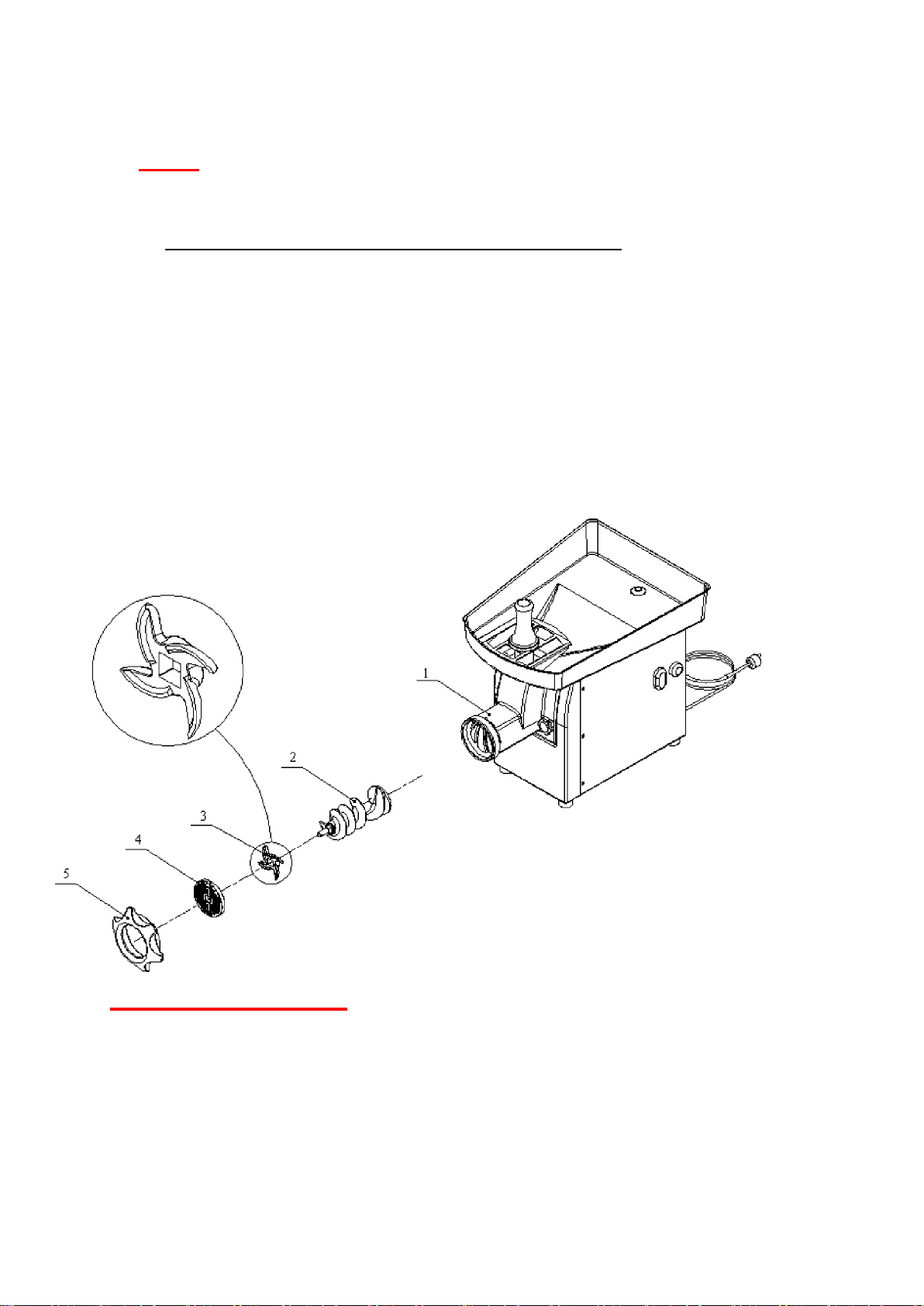
4.2.1 SYSTEM 2 CUTTING ELEMENTS (enterprise).
A- Insert the helix (2) inside the body (1) with a slight twisting
motion for a good engagement with the hex output shaft engine.
B-Fit Knife (3).
C-Mount Plate (4).
D-mount stainless steel nut (5).
VERY IMPORTANT :
It is essential to follow the order of assembly.
Do not mount the entire body / propeller and
cutting system at once.
Installation should be done as described above in
several phases.
6

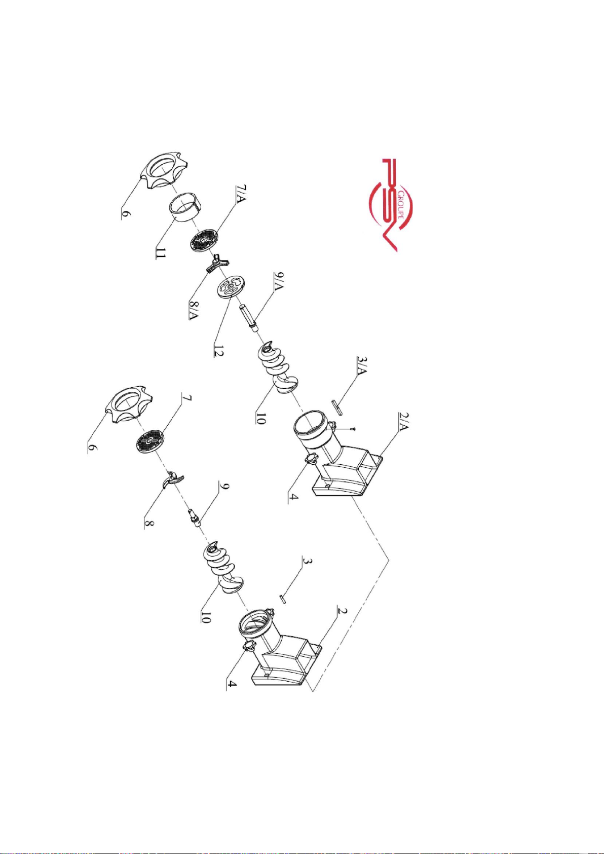
4.2.2 SYSTEM WITH 3 CUTTING ELEMENTS (UNGER).
NOTE : Disconnect the machine from the electricity grid
for the following:
Insert the A-helix (2) inside the body (1) with a slight twisting
motion for a good engagement with the hex output shaft engine.
B-Fit the knife plate
(3). C-Mount the blade
(4). D-Mount plate (5).
E-Assemble the ring (6).
F-mount stainless steel nut (7).
VERY IMPORTANT :
It is essential to follow the order of assembly
Do not mount the entire body / propeller and
cutting system at once.
Installation should be done as described above in
several phases.
7

4.2.3 SYSTEM WITH 5 CUTTING ELEMENTS (UNGER).
NOTE : Disconnect the machine from the electricity grid for the
following:
Insert the A-helix (2) inside the body (1) with a slight twisting
motion for a good engagement with the hex output shaft engine.
B-Fit the knife plate (3).
C-Mount the blade (4).
D-Mount plate (5).
E-Fit the knife (6).
F-mount plate (7).
G-Install the ring (8).
4.2.4 PRECAUTIONS FOR INSTALLATION AND MAINTENANCE
SYSTEM UNGER
Make sure that the cutting system is mounted exactly as shown
below. Improper installation, including upside down, causing
breakage of the blades or plates.
The plate must be perfectly knife against the face of the body of
the chopper.
The nut stainless steel machine should not be tightened
significantly.
Change the blades before they are flush with the branches of
the knife.
To surface plates from wear. Plates prevent waste a perfect fit
and cause rapid wear of the blades.
8

A- CUTTING PLATE
B-DOUBLE FACE KNIFE (shoulder outlet plate side )
C-PLATE WITH HOLES
5 Maintenance
DISCONNECT BEFORE ANY WORK ON THE UNIT
9

5.1 Cleanning the machine
For obvious reasons of hygiene, meat mincing machines
require extensive and frequent cleanings. They must be kept
perfectly clean and maintenance, disassembled, cleaned
and disinfected after each half day of work.
To do so, we recommend to use detergent (like dish soap or
ammonia products).
5.2 Preliminary cleanning
Remove visible dirt by brushing (body, propeller, screw, plates
and knives).
5.3 Disinfection
Immerse all removable parts in a bath of warm water
(Temperature 45-55 ° C.) with a detergent-disinfectant
appropriate.
For the plate and body wash in warm water with the
same detergent-disinfectant.
5.4 Rinse
Rinse the removable parts, rinse the plate, and the body.
Do not immerse the device. Do not clean the jet pressure
The brushes used must be cleaned in a detergent solution
and rinsed.
The body of the chopper does not require special maintenance.
Just use a towel or disposable paper moistened.
Avoid using abrasive cleaners that will damage the
steel. Sponges are prohibited.
5.5 Maintenance
The gearbox requires no maintenance.
10

6 Warning
PROTECTION AGAINST THE RISK OF CUTS CAUSED BY
KNIVES:
There is a serious risk when the operator can move the fingers
through the plate of hash, as the knife rotates in contact with it.
When the holes have a diameter less than 4mm, the risk of
introduction of the fingers does not exist (CF NF E 09-010). It is
the same for diameters between 4 and 8mm included, provided
that the plate has a thickness of 5mm.
For hole diameters greater than 8mm or specially shaped
openings (in beans for example), it is necessary to develop a
device that prevents access to the dangerous part.
7 Accessories
Your device comes with a pestle in food.
8 Customer service
After-sales service is performed by your dealer:
He will ensure the start and the possible restoration of your
device and he will provide spare parts and accessories.
11

9 Warranty
As a manufacturer, we guarantee our equipment one year
against any manufacturing defect, the bill acting as a warranty.
IMPORTANT:
The electrical and electronic parts are excluded from the
Warranty.
LIMIT OF OUR GUARANTEE:
The warranty applies only to the purchaser and not to
third parties to which the material could be resold.
Our guarantee is limited to replacement or repair free of parts
found defective by us. In this case, the material is returned to us
prepaid.
The port and the workforce are in all cases be borne by our
distributor.
All comments and not misuse by special instructions, changes,
modifications, or repairs outside the workshop of an authorized
dealer, and the lack of identification plate, resulting in the
cancellation of the guarantee.
12

10 DRC 32/98 nomenclature
NOMENCLATURE OF MINCER DRC 32/98
DESIGNATION
REPERE
REF-PSV
PLATE STEEL PLATE GUARD + MAIN (ALL SODA)
1
922
MAGNET ORDER
2
924BIS
BODY STAINLESS-32-SC / / BODY STAINLESS-98-DC
3 // 3A
913 SC / 913 DC
PIN PLATE CUTTING / / KEY CUTTING PLATE
4 // 4A
918 SC / 918 DC
HANDLE CLAMP BODY
5
919
STUD MOUNTING BODY
6
917
NUT STAINLESS STEEL
7
915
PLATE CUTTING / SC / CUTTING PLATE DC
8 // 8A
N32/5mm//B98/5mm
KNIFE 32-SC / / KNIFE 98-DC
9 // 9A
CTX_N32S // CTX_B98
AXE KNIFE HOLDER SC / / AXE KNIFE HOLDER DC
10 // 10A
916SC // 916DC
STAINLESS STEEL PROPELLER 32
11
914
RING OF COMPENSATION
12
920
PLATE KNIFE DC
13
B98/00
CRANE STEEL SHEET (ALL SODA)
14
925
GEAR COVER MOUNTING SCREW CHC
15
ZVIS910
GEAR COVER
16
912
LIP TYPE SEAL AS
17
907
ELASTIC RING BORE (CIRCLIP)
18
901
NEEDLE BEARING
19
900
CORRUGATED WASHER
20
929
THRUST WASHER BEARING AS
21
903
AXIAL NEEDLE CAGE AXK
22
902
THRUST WASHER BEARING LS
23
904
WHEEL SHAFT
24
930
SHIM WASHER
25
NEEDLE SLEEVE HK
26
905
BODY REDUCER
27
911
CAP GASKET
28
909
OIL FILLER CAP
29
910
LIP TYPE SEAL AS
30
908
STANDARD MOTOR FLANGE
31
931
INSERT PAN
32
2 SUPPORT PLATE ELECTRICAL BOX
33
1 SUPPORT PLATE ELECTRICAL BOX
36
13

FLAT WASHER
37
ZVIS10-004
OUTDOOR FAN WASHER
38
PLATINUM POWER WITH HOUSING
39
934
BASE (ALL SODA)
40
926-2
SCREW FIXING GEAR THEF
41
ZVIS057
SCREW FIXING GEAR THEF
42
ZVIS110
OUTDOOR FAN WASHER
43
FLAT WASHER
44
NUT
45
ZVIS025
STAINLESS STEEL BODY
46
926-1
DOUBLE BUTTON
47
936
SEALED PUSHBUTTON CAP
48
936 A
PUSH BUTTON
49
935
PUSH BUTTON LABEL
935 A
SEALED PUSHBUTTON CAP
50
935 B
DETECTION SENSOR PLATE
51
924
SUPPORT PLATE
52
926
OUTDOOR FAN WASHER
53
PLATE MOUNTING BRACKET SCREW CHC
54
SCREW MOUNTING BODY TCL
55
SCREW MOUNTING BODY TRL
56
GREY RUBBER FOOT
57
129
FLAT WASHER
58
RUBBER FOOT MOUNTING SCREW TCL
59
REAR STEEL SHEET
60
926-3
PRESS GLAND PG13, 5 + NUT BLACK
62
923
PHASE CABLE / / PHASE CABLE
63
ZCAB003 // ZCAB002
PILON
66
921
OUTDOOR FAN WASHER
67
SCREW HEX HEAD FULL THREAD
68
14
11 Exploded scheme DRC 32/98
15

16
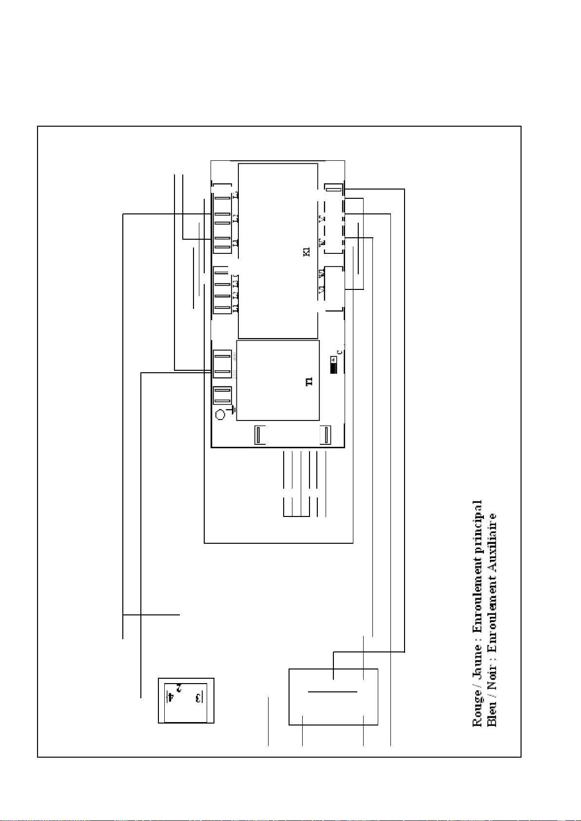
12 Electric Scheme
Y Y
N
11f13.LO u
o
o
E
I = 1
I = 1
I = 1
I = 1
I = 1
2
5
I = 1
I = 1
I = 1
o
o
1=.
o
I
12
1o
0
011H El
El
1=1
C.1
rq
o
r t i
O
O
O
Fy
8SZ1711DZ
uomul
17
This manual suits for next models
3
Table of contents
Other PSV groupe Kitchen Appliance manuals


