PTC Instruments e2000 512D User manual

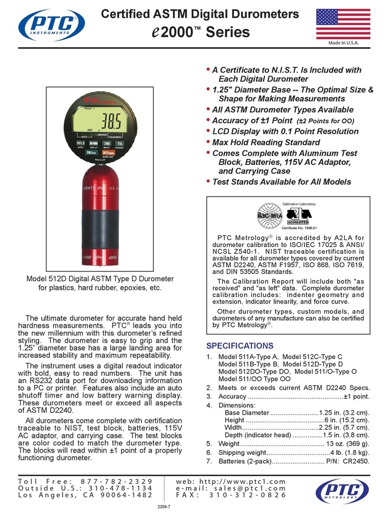
e2000 Digital Durometer
ASTM Type D Model 512D
• Accuracy ±1 Point
• 1.25” Diameter Base
• Max Hold Pointer Standard
• LCD Display with 0.1 Point Resoluon
• Two CR2450 baeries included
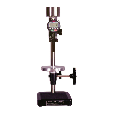
• Accessory Test Stands Available
• Each Instrument comes with a Cercate to N.I.S.T.
• Meets or Exceeds Current ASTM D2240 Specicaons for Type D
• Includes Aluminum Test Block, 115V AC Adaptor and Sturdy Carrying Case
Toll Free: 877-782-2329 Outside the US: 310-478-1134
SPECIFICATIONS
Range (Type D) 0 to 100 points
Accuracy ±1 point
Test Block (included) Model 402D
Height 6 in. (15.2 cm)
Width 2-1/4 in. (5.7 cm)
Depth 1-1/2 in. (4.4 cm)
Weight 13 oz. (227 g)
Shipping Weight 4 lb. (1.8 kg)
PTC Metrology™ is accredited by A2LA for durometer
calibraon to ISO/IEC 17025 & ANSI/NCSL Z540-1. NIST
traceable cercaon is available for all durometer types
covered by current ASTM D2240, ASTM F1957, ISO 868, ISO
7619 and DIN 5305 standards.
The calibraon report will include both “as received” and
“as le” data. Complete durometer calibraon includes
Indenter Geometry and Extension, Indicator Linearity and
Force Curve.
Other durometer types, custom models and durometers
from other manufacturers can also be cered by PTC
Metrology™.
PTC® products are covered by a limited liability warranty from defects in
material and workmanship for one year from date of purchase. This
warranty does not apply if, in the judgement of PTC®, the product fails
due to damage from shipment, handling, storage, accident, abuse or
misuse, or if it has been used or maintained in a manner not conforming
to product's instrucons, has been modied in any way, or has a defaced
or removed serial number. Repair by anyone other than PTC® or an
approved agent voids this warranty. The maximum liability of PTC® is the
product purchase price.
LIMITED LIABILITY WARRANTY
ASTM Type D Durometers are for determining indentaon hardness of
Pipeline Coang, Hard Rubber, Acrylic, Delrin, Kevlar, PVC, Nylon, Lexan
and Epoxies.
The ulmate durometer for accurate hand held hardness
measurements. PTC® leads you into the new millennium
with this durometer’s rened styling. The durometer is
easy to grip and the 1.25” diameter base has a large
landing area for increased stability and maximum
repeatability.
The instrument uses a digital readout indicator with bold,
easy to read numbers. The unit has a data port for
downloading informaon to a PC or printer.
Features also include an auto shuto mer and low
baery warning display.
The test blocks are color coded to match the durometer
type. The blocks will read within ±1 point of a properly
funconing durometer.

OPERATING INSTRUCTIONS
The following procedures are based on ASTM Standard
D2240. This standard is recognized as being denive,
however, not all applicaons require such stringent
controls.
Readings below 10/D may be inexact and should be made
on a Type A durometer.
The surface of the sample to be tested shall be clean and
smooth. The sample should be at least 1/4” (6 mm) in
thickness unless it is known that idencal results are
obtained with a thinner specimen. Thinner materials can be
stacked to obtain the minimum thickness (DO NOT GLUE).
Such results may not agree with those of a solid specimen.
The sample should be large enough so that the indenter is
at least 1/2” (12 mm) from any edge unless it is known that
idencal results are obtained when measurements are
made closer to the edge. The surface of the specimen shall
be at over a sucient area to permit the presser foot to
contact the specimen over an area having a radius of at
least 1/4” from the indenter point. The temperature of the
specimen should be 73.4°F ±3.5°F (23°C ±2°C). The
specimen should be allowed to rest at this temperature for
at least 1 hour prior to tesng, as the properes of most
materials change with temperature.
Place the specimen on a hard, horizontal surface. With the
durometer held vercally, press and hold release the 'ON/
clr' buon to turn on the digital indicator.
If desired, press and release the 'HOLD' buon to enable
max-hold. Hold the durometer vercally with the point of
the indenter at least 1/2 " from any edge. Apply the presser
foot to the specimen as rapidly as possible, without shock,
keeping the foot parallel to the surface of the specimen.
Apply just sucient force to obtain rm contact between
the presser foot and the specimen. Hold for 1 or 2 seconds,
the maximum reading can be obtained by a seng on
the indicator (see above). When max-hold is enabled the
maximum value reached will automacally be displaced
and held unl reset. To disengage the maximum feature,
press and release 'HOLD' buon again. If other than a
maximum reading is needed, hold the durometer in place
without moon
and obtain the reading aer the required me interval.
Make 5 tests at least 1/4" apart and use the average value.
PTC® Instruments is the leading manufacturer of durometers and surface thermometers in the world. Our factory and calibraon lab is
located in Los Angeles, California U.S.A. Doc #2469
DIGITAL INSTRUCTIONS
Power On
Press and hold ON/CLR unl indicator turns on.
Power O
Press OFF/MODE
Auto-O Toggle
Press the 2ND buon unl 2ND appears on the display.
Press the OFF/MODE.
An hour glass appears at le side of display if AUTO OFF is
acve. If AUTO OFF is acve the indicator will power o in
10 minutes with no acvity (buon press or spindle
movement).
Hold Mode
Allows you to hold the value on the display according to
the specied mode.
Press HOLD to toggle hold mode on and o.
MAX - Holds and displays the highest reading aained.
MIN - Holds and displays the lowest reading aained.
FRZ - Holds and displays the reading displayed when HOLD
is engaged.
Note: Pressing ON/CLR buon resets indicator to spindle
posion except in FRZ; resets to zero.
Reset to Factory Default
This will set all features and funcons back to the factory
default sengs.
Press the 2ND buon (2ND icon should appear on the
display), followed by ON/CLR, then press IN/MM.
Note: Factory defaults cannot be reset if the LOCK feature
is on.
For a complete calibraon check of mainspring, and visual and
mechanical check of indenter, the instrument should be
returned to PTC Metrology ™
(See Guarantee & Calibraon Service) or refer to ASTM D2240
Specicaons. PTC® recommends the unit be returned at least
every 12 months for this check. For a quick eld check, follow
the guideline below. Under no circumstance should a test block
be used as a standard to calibrate a durometer.
1. The pointer should read zero when no force is applied to the
indenter of the durometer.
2. Hand hold the durometer and insert the indenter into the
hole of the calibrated test block. Apply enough force to make
rm contact between the top surface of the test block and the
base of the durometer. The dial reading should agree with the
value stamped on the check block (±1). Several tests should be
made and the results averaged.
3. The indenter must protrude 0.098 to 0.100 inches below the
base of the durometer.
4. When the indenter is fully displaced, the durometer should
read 100 points. Use care as to not damage the p of the
indenter.
CALIBRATION CHECK
Other PTC Instruments Measuring Instrument manuals
