GASTRON GPD-100 User manual
Design, Develop, Manufacture, Install and Maintenance Service for Gas Leak Alarm
DOC NO.G -046IM00E
GPD-100
Instruction Manual
Revision: 1.1
Copyright ⒞GAS RON, Co., L D. All rights reserved.
For proper use, please read this manual carefully prior to
GPD-100 Instruction Manual
PAGE
2 of 27
Rev 1.1(2019.05.23)
Thank you for purchasing our GASTRON’s product.
Gastron is a specialized company in producing gas detector and gas monitoring system.
We have been recognized by customers for our best quality products and excellence in easy-to-
use design. We are striving to provide the suitable product that fits customer’s needs, and
continuously put every effort to develop better gas detector to satisfy customer’s requirements.
From now on, we will be your reliable partner to shed a bright light on your concern about gas
detector. Please contact us if you have any question. You can obtain best solution from us with
great satisfaction.
his instruction manual describes how to operate the gas detector. It also briefly explains how
to repair and maintain the device. Please keep this manual in safe place after reading carefully.
his instruction manual will be of great help when you encounter any trouble or question while
you are using the device.
If you have any problem when using our product, contact us to following address:
Address: 18-8, Dogeumdanji 1-gil(Palgok 2-dong), Sangrok-gu, Ansan-si, Gyeonggi-do
el : 031-490-0800
Fax : 031-490-0801
URL : www.gastron.com
E-mail : gastron@gastron.com
Note
• We recommend that the gas detector should be inspected and
calibrated with calibration gas prior to use for accurate operation.
• Without getting calibrated, the device might be malfunctioned due to
sensor aging problem.
• When it is necessary to disassemble the device, technician with special
skills for a gas detector must perform it.
• For more details about maintenance and calibration of gas detector,
contact our technical department via email or visiting our web site.
GASTRON reserves the right to change published specifications and designs without prior notice.

GPD-100 Instruction Manual
PAGE
3 of 27
Rev 1.1(2019.05.23)
TABLE OF CONTENTS
1.
Introduction ......................................................................................................................4
2.
Structure ..........................................................................................................................4
3.
Specification .....................................................................................................................5
3.1.
General Specifications .................................................................................................5
3.2.
Mechanical Specifications ............................................................................................5
3.3.
Electrical Specifications (Standard ype) .......................................................................5
3.4.
Environmental Specifications .......................................................................................6
4.
Name and Functional Description of Components ..............................................................6
4.1.
Composing Elements ...................................................................................................6
4.2.
Front Panel Display part ...............................................................................................7
5.
Operation .........................................................................................................................9
5.1.
Connecting Sampling Probe ........................................................................................9
5.2.
Power On ...................................................................................................................9
5.3.
Gas Measurement Mode .............................................................................................9
5.4.
Mode Configuration .................................................................................................. 10
5.5.
Power Status ............................................................................................................. 10
5.6.
How to use a log mode ............................................................................................. 11
5.6.1.
Gas log file ....................................................................................................... 13
5.6.2.
Report log file ................................................................................................... 13
6.
System Mode .................................................................................................................. 15
6.1.
Mode configuration .................................................................................................. 15
6.2.
Detailed Mode description ......................................................................................... 15
6.3.
Configuration Mode .................................................................................................. 16
6.4.
Program setting mode ............................................................................................... 18
6.5.
Zero Calibration ........................................................................................................ 19
6.5.1.
Auto Zero Calibration ....................................................................................... 19
6.5.2.
Manual Zero Calibration ................................................................................... 19
6.6.
Span Calibration ........................................................................................................ 20
6.7.
Alarm mode .............................................................................................................. 21
6.8.
Log Save Mode ......................................................................................................... 22
7.
roubleshooting .............................................................................................................. 24
7.1.
Fault Code ................................................................................................................ 24
7.2.
Warning Code ........................................................................................................... 24
7.3.
Recovery List ............................................................................................................. 25
8.
Appearance and Dimensions ........................................................................................... 26
9.
Revision History ............................................................................................................... 27

GPD-100 Instruction Manual
PAGE
4 of 27
Rev 1.1(2019.05.23)
1. Introduction
he GPD-100 is a portable gas detector that has been developed to detect a variety of gases so
as to prevent serious accidents caused by unexpected gas leaks in hazardous areas such as
industrial plants, gas storage facilities and factories in the process of producing or consuming
combustible gases and toxic gases.
he portable gas detector GPD-100 continuously monitors the air for detecting dangerous gas
leaks and displays the measured value of gas concentration. It makes a visual signal and an
audible alarm when it detects gas leaks.
2. Structure
he body of GPD-100 is made of polycarbonate-ABS housing. A sampling pump is equipped
inside the GPD-100. he sampling pump pulls the air containing leaked gas in the device.
he GPD-100 mainly consists of three parts as follows: (1) LED that presents the measured
value of gas concentration and shows alerts to the user at front panel, (2) Port that takes in and
releases gas, and (3) terminal that enables to connect USB, Micro SD card and DC jack. A sensor
is a removable cartridge type, so that it can be easily detached and replaced.
[Figure 1. GPD-100 Overview]

GPD-100 Instruction Manual
PAGE
5 of 27
Rev 1.1(2019.05.23)
3. Specification
3.1. General Specifications
I T E M S S P E C I F I C A T I O N
Measuring ype Auto Sampling type
Display ype Flexible Numeric Display LED
Measuring Method
Electrochemical / Cartridge
Catalytic/ Cartridge
semiconductor / Cartridge
Photoionization detector(PID) / Cartridge
Detectible Gas Flammable gas, oxic gas, Oxygen (Note1)
Measuring Range 000.0 ~ 9999(Note1)
Accuracy ≤ ±3% / Full Range
Zero Drift ≤ 2% / Full Range
Response ime
arget gas response time may vary. Refer to the
sensor module datasheet or contact GAS RON for
specific sensor data.
Pump ype
Diaphragm Pump
Flow Rate 100 ~ 1,000 ml (Normal 300~500ml / min)
Gas Sample Line 5m ( 1/4" ube )
Approvals Classification CE ( No. K5004/E12 )
Storage SD Card
Warranty Main Unit 2Year
Sensor 1Year
Note1. Refer to the “List of detectable gases & vapours” or contact GASTORN for specific gas
3.2. Mechanical Specifications
I T E M S S P E C I F I C A T I O N
Dimension / mm 218(W) × 95(H) × 100(D) mm
Weight including Sensor App. 1.2kg
Sample gas vent / inlet 1/4" eflon ube
Body material PC-ABS(polycarbonate-ABS)
3.3. Electrical Specifications (Standard Type
I T E M S S P E C I F I C A T I O N
Battery ype Lithium-Ion DC 7.4 V / 4.3A
Charge ime 4 Hours
Operating ime Normal Sensor ype 10 Hours
CEC Sensor ype 5 Hours
Charge Voltage
DC 12V /2A
AC Adapter Input Voltage AC100~230V 50/60Hz

GPD-100 Instruction Manual
PAGE
6 of 27
Rev 1.1(2019.05.23)
3.4. Environmental Specifications
I T E M S S P E C I F I C A T I O N
peration Temperature
Main Unit
-10 to 60 ℃
Sensor
Sensor dependant, Refer to the
sensor module datasheet or contact
GASTR N for specific sensor data.
Storage Temperature
Main Unit
-10 to 60 ℃
Sensor
Sensor dependant, Refer to the
sensor module datasheet or contact
GASTR N for specific sensor data.
peration Humidity
Main Unit
5 to 99% RH (Non-condensing)
Sensor
Sensor dependant, Refer to the
sensor module datasheet or
contact GASTR N for specific
sensor data.
Pressure Range 90 to 110KPa
Max. air velocity 6m/s
4. Name and Functional Description of Components
4.1. Composing Elements
[Figure 2. GPD-100 구성요소]

GPD-100 Instruction Manual
PAGE
7 of 27
Rev 1.1(2019.05.23)
4.2. Front Panel Display part
[Figure 3. 전면 Display 구성도]
No Name Descriptions
1 Calibration icon Indicating that calibration procedure is being processed.
2 Setting icon Indicating that value setting operation is being processed.
3 Pump Icon Pump Operation Status display
4 est Icon
Indicating that gas detector operates in test mode.
5 ime setting Icon
It turns on when internal time is being set.
6 Setup Status Icon
It turns on when internal time is being set.
7 AC Adaptor Icon Indicating that AC adapter connection status
8 Battery Icon Indicating that Battery charging status
9 Measurement Unit
Indicating that current measuring unit presented on
screen.(PPM, PPM, %VOL, %LEL, mA)
10 Flow Rate When this icon appears, measured value of flow is indicated as
10 different levels, while in normal measuring state.
11 Communication
Icon his icon is turned on, when USB communication is being used.
12 Lock Icon Indicating device is in lock mode. Configuration mode is not
allowed.
13 CEC Icon Indicating that CEC operation status
14 rouble icon It turns on when fault is detected
15 Alarm2 icon Indicating that 2
nd
alarm is set or detected.
16 Alarm1 icon Indicating that 1
st
alarm is set or detected.
17 Zero, Span icon Indicating that zero or span mode is entered during calibration
18 Gas concentration
display It is used for displaying measured value or message to the user

GPD-100 Instruction Manual
PAGE
8 of 27
Rev 1.1(2019.05.23)
19 Power LED his Power LED is turned on when power is successfully
supplied.
20 rouble LED his rouble LED is turned on when a device is recognized as
malfunctioned
21 Alarm LED his Alarm1 LED is turned on, when the measured value of gas
concentration exceeds the preset value of Alarm1 level
22 Power Key Power on /off control key
23 RUN / MODE Key his key is used for changing setting mode or measuring mode.
24 AU O ZERO Key Auto Zero calibration key
25 Down Key It is a key to decrease a setting value in function setting mode.
26 Up Key It is a key to increase a setting value in function setting mode.
27 RESE key In function setting mode, Reset Key is used for recovering the
device’s state back to menu state or standby state.
[Ta le 1. Front Display part description]

GPD-100 Instruction Manual
PAGE
9 of 27
Rev 1.1(2019.05.23)
5. Operation
5.1. Connecting Sampling Probe
Connect a sampling Probe(1/4”Teflon tube) to a gas inlet port
Figure 4. Sampling Port Conne tion
5.2. Power On
Press power switch( ) and hold it more than 2 seconds. Then it starts up.
Power LED turns on and ‘L Ad’ is displayed (during about 15 seconds) indicating sensor
data is being loaded. After ‘WaIt’ is displayed, make sure that ‘Stby’(stand by) shows up
blinking.
When you turn on the power switch, version information will show up
in LCD like “U-XX”. hen “L0Ad”(Load) message flashes on and off
during about 15 seconds. Once warming-up is finished, “Stby”(Stand by)
message will come up, which indicates that the device is now ready to
measure. If the device detects a fault in device or sensor cartridge, a
faulty alarm occurs.
5.3. Gas Measurement Mode
When you press a switch “RUN/MODE”, the device will count down from
20 to 1, which is the time duration necessary to allow the sensor to
stabilize. When it reaches to 0, the measured value of gas concentration
is displayed on LCD.
Note 1)
In the occurrence of fault in sensor cartridge, error message
ranging from “E-10” to “E-33” flashes in LCD and also trouble LED turns
on. (Please refer to error and warning messages)
Note 2)
In case where gas concentration value is greater than 10% of
specified high scale value, “OuEr” message flashes every half a second.
Note 3)
Sensor stabilization time varies depending on the sensor type.
In case of combustible sensor : 10 seconds
In case of toxic sensor : 20 seconds

GPD-100 Instruction Manual
PAGE
10 of 27
Rev 1.1(2019.05.23)
5.4. Mode Configuration
5.5. Power Status
Item Power Icon disp ay Description
Full charge
Full charge status. utline of the battery icon
keeps blinking. Battery is not charged in this
state.
80%
charge
more than 80% of Battery level indicator
60%
charge
more than 60% of Battery level indicator
40%
charge
more than 40% of Battery level indicator
20%
charge
more than 20% of Battery level indicator
5% charge
Battery low message shows up in LCD and
battery icon keeps blinking.
charging
status
This icon keeps blinking when battery is
being charged. When AC adaptor is
recognized after it is inserted, this icon turns
on.
[Table 2. Power Status des ription]
While the device displays ”Stby”(Stand by), press and hold “RUN/MODE” key
more than 2 seconds. hen you will enter menu selection mode.
Password entering screen shows up. Input password using “ ”Key or
“ ”Key. If you press “RUN/MODE” key after entering password, then you
enter a configuration menu (“ConF”) (Initial password: [--]).
Select “COnF”(configuration) using “ ” key or “ ” key and then press
“RUN/MODE” key. You will enter environment configuration mode.

GPD-100 Instruction Manual
PAGE
11 of 27
Rev 1.1(2019.05.23)
5.6. How to use a log mode
When you want to read data stored in an external memory after operating the log mode,
connect the external memory to PC.
You can see the folders named by date when the data has been stored. he date is
determined by the date you set in “tImE” mode. (04-17 folder of the figure below, displays
the April 17)
[Figure 5. Date folders stored in SD card]
Inside the folder named by date, there are folders named by time(hour_min_sec) stored.
Each of these folders contains log data regarding measurement record and equipment
information. (04-17 folder of the figure below, displays the April 17)
[Figure 6. Time folders generated in date folder]
hree types of files are generated as log data in the hour_min_sec folder.

GPD-100 Instruction Manual
PAGE
12 of 27
Rev 1.1(2019.05.23)
[Figure 7. Log data files saved in time folder]
File Name Descrip ion
Gas Log File GAS00. X Log about gas measurement records
Report File REPOR . X Log about System Status and
Measurement Status
System File INFO.DA System File
[Ta le 3. Log File description]
GPD-100 Instruction Manual
PAGE
13 of 27
Rev 1.1(2019.05.23)
5.6.1. Gas log file
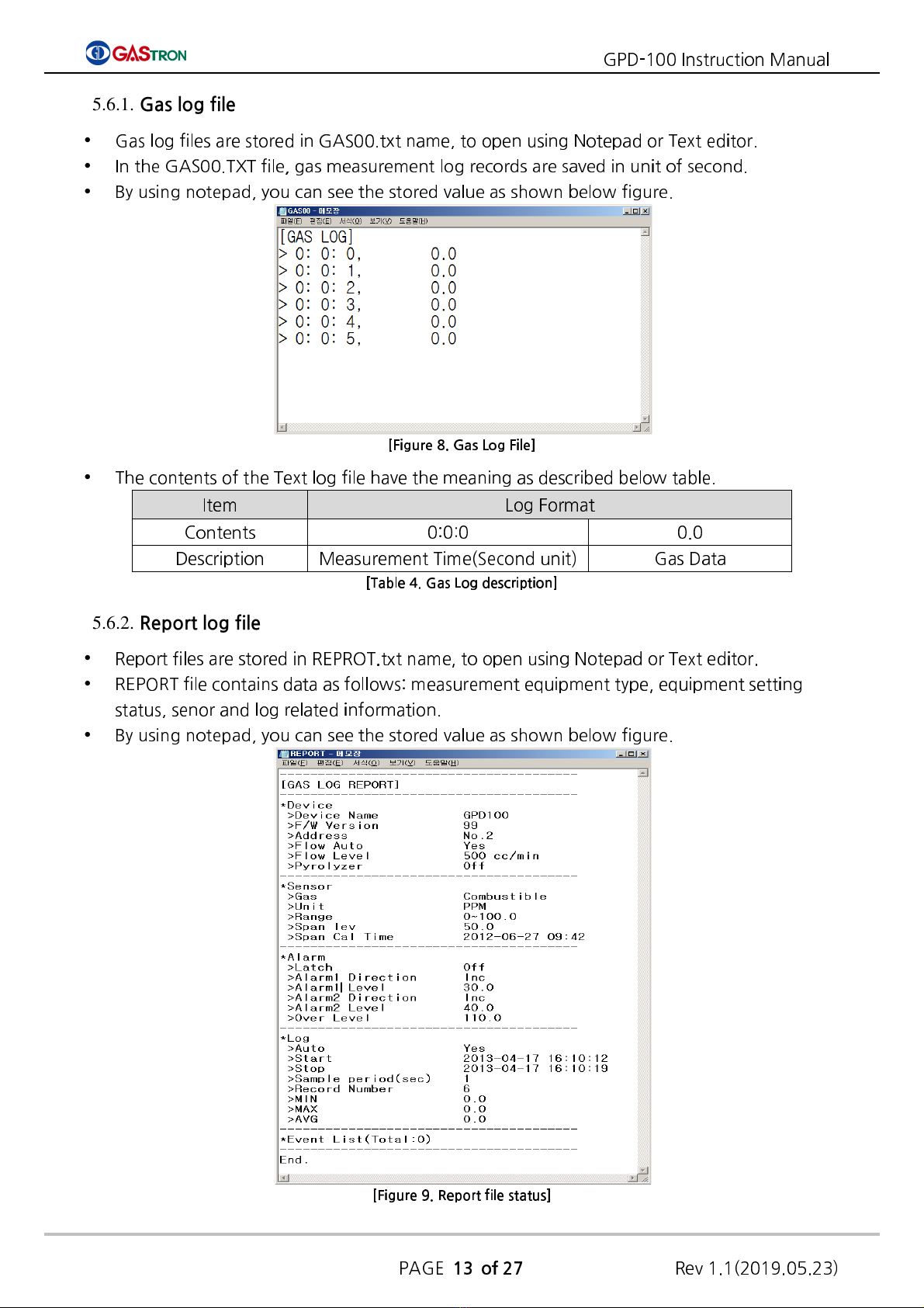
Gas log files are stored in GAS00.txt name, to open using Notepad or ext editor.
In the GAS00. X file, gas measurement log records are saved in unit of second.
By using notepad, you can see the stored value as shown below figure.
[Figure 8. Gas Log File]
he contents of the ext log file have the meaning as described below table.
Item Log Format
Contents 0:0:0 0.0
Description Measurement ime(Second unit)
Gas Data
[Ta le 4. Gas Log description]
5.6.2. Report log file
Report files are stored in REPRO .txt name, to open using Notepad or ext editor.
REPOR file contains data as follows: measurement equipment type, equipment setting
status, senor and log related information.
By using notepad, you can see the stored value as shown below figure.
[Figure 9. Report file status]
GPD-100 Instruction Manual
PAGE
14 of 27
Rev 1.1(2019.05.23)
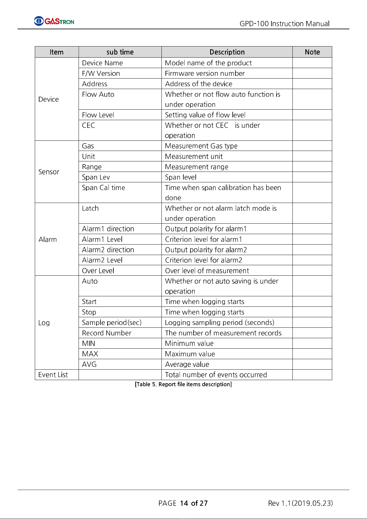
I em sub ime Descrip ion No e
Device
Device Name Model name of the product
F/W Version Firmware version number
Address Address of the device
Flow Auto Whether or not flow auto function is
under operation
Flow Level Setting value of flow level
CEC Whether or not CEC is under
operation
Sensor
Gas Measurement Gas type
Unit Measurement unit
Range Measurement range
Span Lev Span level
Span Cal time ime when span calibration has been
done
Alarm
Latch Whether or not alarm latch mode is
under operation
Alarm1 direction Output polarity for alarm1
Alarm1 Level Criterion level for alarm1
Alarm2 direction Output polarity for alarm2
Alarm2 Level Criterion level for alarm2
Over Level Over level of measurement
Log
Auto Whether or not auto saving is under
operation
Start ime when logging starts
Stop ime when logging starts
Sample period(sec) Logging sampling period (seconds)
Record Number he number of measurement records
MIN Minimum value
MAX Maximum value
AVG Average value
Event List otal number of events occurred
[Ta le 5. Report file items description]

GPD-100 Instruction Manual
PAGE
15 of 27
Rev 1.1(2019.05.23)
6. System Mode
6.1. Mode configuration
Menu structure of the device is as following table.
I em Display Descrip ion No e
CONFIGURA ION MODE CONF Configuration of internal
function
PROGRAM MODE PRGM Configuration of related gas
measurement
CALIBRA ION MODE CALB Calibration gas
ALARM MODE ALAM Configuration of Alarm setting
IME MODE IME Setting of Internal ime Factory Mode
SENSOR DA A MODE S-D Check of sensor data Factory Mode
ES ES MODE est Mode Factory Mode
FLOW MODE FLOW Configuration of flow setting Factory Mode
Log Mode Log Configuration of log function
MAIN ENANCE MODE M- Configuration of Maintenance
setting Factory Mode
[Ta le 6. Mode Configuration]
6.2. Detailed Mode description
Detailed menu and sub-menu of the device is as following table
Level 1 Level 2 Level 3
COnF
Configurat
ion
Add Specify a detector
number [01] ranges between 01 and 64
PSWd
Set password [00] ranges between 00 and 99
SUPr
Set the measured gas
suppression rate OFF 1~50%
PyrO
Set if CEC is used or not ON / OFF
Py-U
Indicate CEC voltage 1.50U
U-00
Program version number
Prgm
Measurem
ent data
UnIt Measurement unit %LEL, %VOL, PPM, PPB
dP-S Specify location of the
decimal point Set 0000, 0.000, 00.00 or 000.0
H-SL Set Full Scale Set value between 0 and 9999
CALb
Calibration
mode
ZERO ZERO Calibration Mode
YES/no
Set ZERO Calibration
0.0
Measured value display
mode
WA t
Under zero calibration
0.0 Measured value after
completing calibration

GPD-100 Instruction Manual
PAGE
16 of 27
Rev 1.1(2019.05.23)
SPAN SPAN Calibration Mode
YES/no
Span calibration setting
50.0
Span calibration value
50.3
Measured value of
standard gas
WAIt
Under span calibration
50.0
Measured value after
completing calibration
ALAm
Alarm
setting
LACH
Alarm occurrence setting
on/ FF
AL-1
Alarm1 value setting 90% setting of 0~Full Scale
1H/1L
Alarm1 operational
direction
H:Upward Alarm
L: Downward Alarm
AL-
Alarm2 value setting 90% setting of 0~Full Scale
H/ L
Alarm2 operational
direction
H:Upward Alarm
L: Downward Alarm
L g Saving log
CtrL Log saving mode n/ FF
AUto Set log auto saving mode
n/ FF
mSdC
Set type of external
memory
[Table 7. Menu Table]
6.3. Configuration Mode
While the device displays ”Stby”(Stand by), press and hold “RUN/MODE” key
more than 2 seconds. hen you will enter menu selection mode.
Password entering screen shows up. Input password using “ ”Key or
“ ”Key. If you press “RUN/MODE” key after entering password, then you
enter a configuration menu (“ConF”) (Initial password: [--]).
Select “COnF”(configuration) using “ ” key or “ ” key and then press
“RUN/MODE” key. You will enter environment configuration mode.
“Add” message will show up. In this state, you can set an address that is
used to identify the device when communicating data.
If you press ”RUN/MODE” key, then you enter an address setting function.
Address is a mode in which you can set the device’s address so as to
identify each detector by PC uniquely. Address number(initially [01]) will
increase or decrease by pressing “ ” or “ ” key.
When desired address is displayed, press “RUN/MODE” key. hen the
address is set to be the number displayed in the screen. After that, the
GPD-100 Instruction Manual
PAGE
17 of 27
Rev 1.1(2019.05.23)
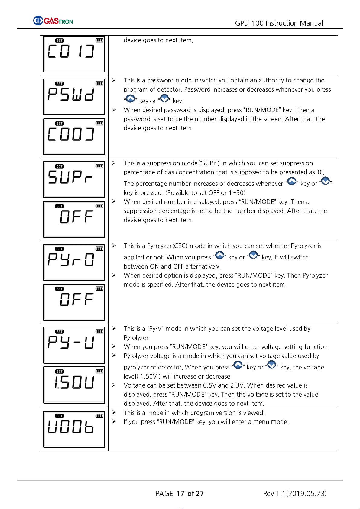
device goes to next item.
his is a password mode in which you obtain an authority to change the
program of detector. Password increases or decreases whenever you press
“ ” key or “ ” key.
When desired password is displayed, press “RUN/MODE” key. hen a
password is set to be the number displayed in the screen. After that, the
device goes to next item.
his is a suppression mode(“SUPr”) in which you can set suppression
percentage of gas concentration that is supposed to be presented as ‘0’.
he percentage number increases or decreases whenever “ ” key or “ ”
key is pressed. (Possible to set OFF or 1~50)
When desired number is displayed, press “RUN/MODE” key. hen a
suppression percentage is set to be the number displayed. After that, the
device goes to next item.
his is a Pyrolyzer(CEC) mode in which you can set whether Pyrolyzer is
applied or not. When you press “ ” key or “ ” key, it will switch
between ON and OFF alternatively.
When desired option is displayed, press “RUN/MODE” key. hen Pyrolyzer
mode is specified. After that, the device goes to next item.
his is a “Py-V” mode in which you can set the voltage level used by
Pyrolyzer.
When you press ”RUN/MODE” key, you will enter voltage setting function.
Pyrolyzer voltage is a mode in which you can set voltage value used by
pyrolyzer of detector. When you press “ ” key or “ ” key, the voltage
level( 1.50V ) will increase or decrease.
Voltage can be set between 0.5V and 2.3V. When desired value is
displayed, press “RUN/MODE” key. hen the voltage is set to the value
displayed. After that, the device goes to next item.
his is a mode in which program version is viewed.
If you press “RUN/MODE” key, you will enter a menu mode.
GPD-100 Instruction Manual
PAGE
18 of 27
Rev 1.1(2019.05.23)
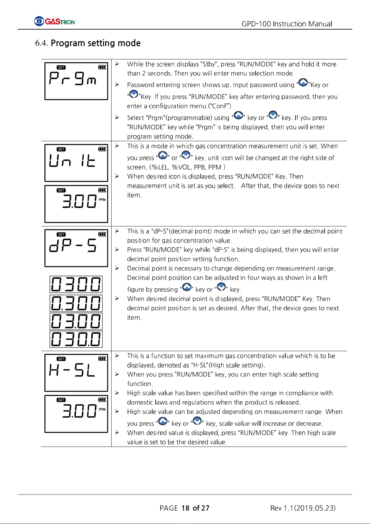
6.4. Program setting mode
While the screen displays ”Stby”, press “RUN/MODE” key and hold it more
than 2 seconds. hen you will enter menu selection mode.
Password entering screen shows up. Input password using “ ”Key or
“ ”Key. If you press “RUN/MODE” key after entering password, then you
enter a configuration menu (“ConF”)
Select “Prgm”(programmable) using “ ” key or “ ” key. If you press
“RUN/MODE” key while “Prgm” is being displayed, then you will enter
program setting mode.
his is a mode in which gas concentration measurement unit is set. When
you press “ ” or “ ” key, unit icon will be changed at the right side of
screen. (%LEL, %VOL, PPB, PPM )
When desired icon is displayed, press “RUN/MODE” Key. hen
measurement unit is set as you select. After that, the device goes to next
item.
his is a “dP-S”(decimal point) mode in which you can set the decimal point
position for gas concentration value.
Press “RUN/MODE” key while “dP-S” is being displayed, then you will enter
decimal point position setting function.
Decimal point is necessary to change depending on measurement range.
Decimal point position can be adjusted in four ways as shown in a left
figure by pressing “ ” key or “ ” key.
When desired decimal point is displayed, press “RUN/MODE” Key. hen
decimal point position is set as desired. After that, the device goes to next
item.
his is a function to set maximum gas concentration value which is to be
displayed, denoted as “H-SL”(High scale setting).
When you press ”RUN/MODE” key, you can enter high scale setting
function.
High scale value has been specified within the range in compliance with
domestic laws and regulations when the product is released.
High scale value can be adjusted depending on measurement range. When
you press “ ” key or “ ” key, scale value will increase or decrease.
When desired value is displayed, press “RUN/MODE” key. hen high scale
value is set to be the desired value.

GPD-100 Instruction Manual
PAGE
19 of 27
Rev 1.1(2019.05.23)
6.5. Zero Calibration
6.5.1. Auto Zero Calibration
6.5.2. Manual Zero Calibration
Alternative way to conduct zero calibration is to start calibration in
measurement state.
Insert clean air or 100% nitrogen through gas in port using calibration tool.
When you press and hold “A UO ZERO” key in measurement mode, AU O
ZERO calibration will start up.
While zero calibration is being performed automatically, “WAIt” message
will display on LCD. If it completes successfully, “gOOd” (Good) will appear
on LCD.
If Zero Calibration fails, “FAIL” will show up during 2 seconds. hen the
device will transit to the calibration mode.
While the screen displays ”Stby”, press “RUN/MODE” key and hold it more
than 2 seconds. hen you will enter menu selection mode.
Password entering screen shows up. Input password using “ ” or “ ”
key. If you press “RUN/MODE” key after entering password, then you will
go to a configuration menu (“ConF”)
Select “CALb”(Calibration) using “ ” key or “ ” key. If you press
“RUN/MODE” key while “CALb” is being displayed, then you will enter
calibration mode.
While “ZERO” icon at the left corner of the bottom is blinking, press
“RUN/MODE” key. hen you will enter Zero Calibration mode.
You can set No/YES using “ ” key or “ ” key.
If you select YES, you will enter zero(0) calibration mode.
Insert clean air or 100% nitrogen through gas in port using calibration tool.
GPD-100 Instruction Manual
PAGE
20 of 27
Rev 1.1(2019.05.23)
6.6. Span Calibration
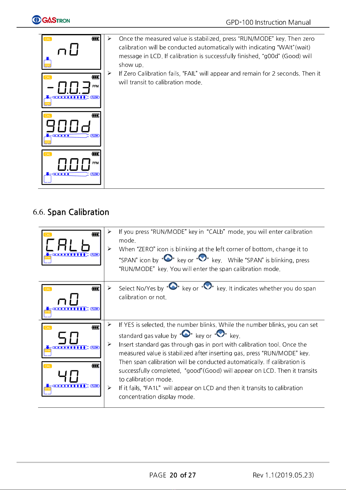
Once the measured value is stabilized, press “RUN/MODE” key. hen zero
calibration will be conducted automatically with indicating “WAIt”(wait)
message in LCD. If calibration is successfully finished, “g00d” (Good) will
show up.
If Zero Calibration fails, “FAIL” will appear and remain for 2 seconds. hen it
will transit to calibration mode.
If you press “RUN/MODE” key in “CALb” mode, you will enter calibration
mode.
When “ZERO” icon is blinking at the left corner of bottom, change it to
“SPAN” icon by “ ” key or “ ” key. While “SPAN” is blinking, press
“RUN/MODE” key. You will enter the span calibration mode.
Select No/Yes by “ ” key or “ ” key. It indicates whether you do span
calibration or not.
If YES is selected, the number blinks. While the number blinks, you can set
standard gas value by “ ” key or “ ” key.
Insert standard gas through gas in port with calibration tool. Once the
measured value is stabilized after inserting gas, press “RUN/MODE” key.
hen span calibration will be conducted automatically. If calibration is
successfully completed, “good”(Good) will appear on LCD. hen it transits
to calibration mode.
If it fails, “FA1L” will appear on LCD and then it transits to calibration
concentration display mode.
Other manuals for GPD-100
3
Table of contents
Other GASTRON Measuring Instrument manuals


Popular Measuring Instrument manuals by other brands

PCB Piezotronics
PCB Piezotronics IMI SENSORS 602D02 Installation and operating manual

Circutor
Circutor CEM-C31-T1 instruction manual

LaMotte
LaMotte SMART3 Operator's manual

Tektronix
Tektronix RFM150 instruction manual

Aeroflex
Aeroflex 9102 user guide

Standard Imaging
Standard Imaging MAX 4000 PLUS user manual

Endress+Hauser
Endress+Hauser Proline Prosonic Flow B 200 Brief operating instructions

Prismatibro
Prismatibro Prisma DI-5C manual

Anritsu
Anritsu Spectrum Master MS2723B Maintenance manual

LOVATO ELECTRIC
LOVATO ELECTRIC DME D305T2 instruction manual

BURK Technology
BURK Technology BTU-4 Installation and operation

Hobo
Hobo RX3000 Series manual


