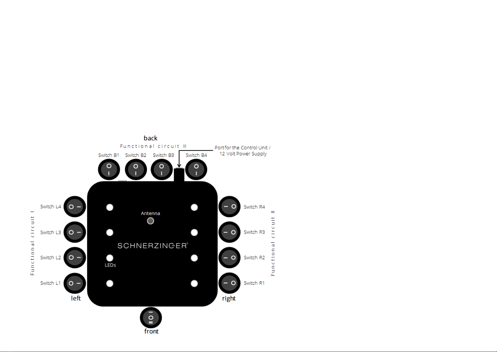
5. Step: Switches back:
Functional circuit II –setting the
GIGA-PULSE clocking
Switches: B1 = low to B4 = high
Starting from the base setting the switches B1 -B4 will be set
sequentially from position 0 to position 1. Each step will
increase the clocking pace.
If the pace is to low, the best possible effect will not be
reached yet. If the pace is to high, even a sound degradation
may occur.
The test ends, when the subsequent step won’t achieve a
better result.
4. Step: Switches right:
Functional circuit I –setting the
GIGA-PULSE LF-bandwidth
Switches: R1 = narrow to R4 = wide
Starting from the base setting the switches R1 -R4 will be set
sequentially from position 0 to position 1. Each step will
increase the bandwidth.
If the bandwidth is to low, the best possible effect will not be
reached yet. If the bandwidth is to high, even a sound
degradation may occur.
The test ends, when the subsequent step won’t achieve a
better result.
Setting up the GIGA PROTECTOR
6
3. Step: Switches left:
Functional circuit I –setting the
GIGA-PULSE HF-bandwidth
Switches: L1 = narrow to L4 = wide
Starting from the base setting the switches L1 -L4 will be set sequentially from position 0
to position 1. Each step will increase the bandwidth.
If the bandwidth is to low, the best possible effect will not be
reached yet. If the bandwidth is to high, even a sound
degradation may occur.
The test ends, when the subsequent step won’t achieve a
better result.