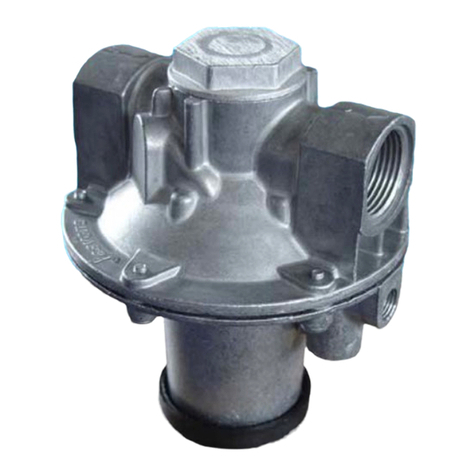
PTI SENTRY 1510 User manual

Operation & Installation Manual
SENTRY™1510
Section 1: Introduction, General Description & Requirements
1.1 Introduction
11984 Rev 01 Page 1of 8
Theory of Operation
The SENTRY 1510 is a pressure regulation controller designed to be used in a
clean room for vertical furnaces. The SENTRY 1510 is installed between the
output of the furnace and the facilities exhaust line. The 1510 can control the
pressure inside the tube to a set point programmed through the furnace controller
or the SENTRY Supervisor.
The SENTRY 1510 isolates the pressure inside the process tube from house ex-
haust pressure variations. The 1510 provides a stable, repeatable process pres-
sure, allowing process optimization and improving process repeatability:
1. The SENTRY 1510 provides a constant pressure (either positive or negative
with respect to the room) for the process. (This allows the process engineer to
optimize the process with respect to pressure. Once optimized, the process
pressure can be fixed, which will then improve the repeatability of film
qualities.)
2. The SENTRY 1510 prevents backstreaming of house exhaust contaminants
into the tube (these contaminants can reduce oxide or diffusion integrity).
3. In the negative pressure configuration, the SENTRY 1510 can reduce the
possibility of HCl fumes escaping into the fab.

11984 Rev 01 Page 2of 8
1.2 General Description
General Description
The SENTRY 1510 consists of two parts:
1. Mechanical pressure regulation based on the "floating piston" concept
2. Electrical set point control, consisting of the SENTRY Supervisor, a pressure
transducer and a stepper motor.
A new pressure set point is provided to the SENTRY Supervisor through the
process tool controller,or it can be changed manually. When the set point is
changed, the Supervisor applies a PID algorithm to the difference between the
new set point and the current process pressure. Based on the results of the PID
Algorithm, the Supervisor commands the stepper motor to increase or decrease
the force on the piston to match the new set point. Once the new set point is
reached, the stepper motor becomes inactive and the "floating piston" takes over
dynamic control.
The "Floating Piston"
The SENTRY 1510 uses the concept of a "floating piston" for its dynamic control.
Figure 2.1 shows a cross section of the SENTRY 1510 controller. There are
several forces acting on the piston:
1. Gravity acting on the mass of the piston, pulling it down.
2. The spring, moving the piston up or down.
3. Clean room pressure, forcing down on the inside of the piston
4. Process pressure on the bottom of the piston
The piston's vertical position forms a gap that changes rapidly in response to fluc-
tuations in facility vacuum, reference port static pressure (clean room air pressure),
or process flows. With constant process flows and exhaust pressure, the piston
will stabilize at a certain height. When a fluctuation occurs, the net force on the
piston will no longer be balanced. The piston will move based on the direction of
the new net force until the forces are once again balanced. Changes in any of
these forces cause the piston to react as follows:
1. The weight of the piston cannot change1
2. The spring can be moved up or down with a stepper motor (this can be thought
of as increasing or decreasing the effective weight of the piston). This changes
the pressure set point (or the pressure to which the valve is controlling) within a
wide house exhaust pressure range. When the house exhaust pressure moves
out of this range, the stepper motor can adjust the spring to maintain the set
point.
1For those familiar with the SENTRY 1000, the movement of the spring changes the effective weight of
the piston, acting like weights added to the piston in the SENTRY 1000.

11984 Rev 01 Page 3of 8
1.2 General Description
3. An increase in clean room air pressure (from a door closing, for example) will
increase the downward force on the piston. The downward movement of the
piston closes the valve, causing the pressure in the chamber to increase,
maintaining a constant pressure differential between the chamber and the
clean room.
4. An increase in facility exhaust (i.e., a more negative exhaust pressure) will in-
crease the pull on the piston, closing off the valve. As the valve is closed off,
the pressure differential across the valve is increased, and the upstream side is
maintained at a constant.
Nitrogen Supply
Nitrogen is supplied to the SENTRY 1510 to perform several necessary functions:
1. Purge of the transducer line to prevent HCl damage
2. A nitrogen curtain in the exhaust line to prevent backstreaming of contaminants
from house exhaust into the process tube
3. A nitrogen bearing to “float” the piston
Figure 1-1:A) SENTRY 1510 input; B) output (Note: the unit shown has custom
fittings and is not shown with the standard female 1" NPT input and output.)

11984 Rev 01 Page 4of 8
1.3 Requirements
4. A “carrier” supply to ensure there is enough flow to provide control, even in the
presence of very low gas flow (for example, during steam processes where
much of the process effluent is condensed prior to the controller)
Figure 1-2shows how the nitrogen is distributed to perform these functions.
Sufficient nitrogen is critical to optimum operation. Without sufficient nitrogen, the
transducer can be damaged and contaminants may back stream from house
exhaust. In addition, if process flow rates drop significantly, the controller
performance may be degraded.
House Exhaust Requirements
Minimum house exhaust requirements are given in Appendix B. However, in many
installations, less house exhaust is required, and in some specific installatios,
additional house exhaust is required. This section allows the user to calculate the
amount of exhaust required for a specific installation.
Calculating minimum house exhaust requirements to operate a “sealed” vertical
furnace at a specified Process Pressure is a relatively simple process; however,
careful attention must be paid to the exhaust path configuration when doing this
calculation. Figure 1-3 is intended to be a guide to assist the user in making this
calculation. This calculation consists of the basic formula:
PSense -(PExit + PController + PFacility) = Minimum House Exhaust Requirement
where;
PSense =Process Pressure or Set-Point within the Sealed Chamber.
N
2
R
R
V
V
Nitrogen
Bias Flow
Nitrogen
“Air”
Bearing
Sense
Line
Purge
Process Pressure
Sense Line
(to process tube)
Pressure
Transducer
Figure 1-2:Nitrogen is used in three different places in the SENTRY 1510.

11984 Rev 01 Page 5of 8
1.3 Requirements
Figure 1-3: Minimum House Exhaust requirements can be calculated from the installation
set up.
PExit =Pressure Drop through exit or condenser plumbing.
PContrroller =Pressure drop through the Controller.
PFacility =Pressure drop through facilities plumbing prior to main H.E. duct.
PSense:Measured Process Pressure
Process pressure or set-point is the operating pressure (negative or positive)
within the “sealed” vertical chamber. With the Sentry 1510, this measurement is
taken at the furnace exit at the transition block (noted by PSense on Figure 1-3)
which connects the quartz exit tube with the Teflon exhaust piping reflecting the
“true” process pressure (PProcess ). The closer the measurement is taken to the
tube, the less pressure difference arises due to pipe length. This is depicted on
Figure 1-3 as Zone A.
PExit : Pressure Drop between Furnace Exit and Controller
This area is noted in the attached Figure 1 as zone B. This pressure drop can be
simply calculated by taking a measurement at the inlet of the Sentry unit and then
subtracting this measurement from the pressure measured at the furnace exit.

11984 Rev 01 Page 6of 8
1.3 Requirements
This pressure drop is a function of the piping diameter and configuration, the
presence or absence of a condenser and, most importantly, the Flow rate (SLM)
through the exhaust line. Pressure drop is increased by long pipe lengths and
elbows in the pipe. If a physical measurement of this pressure drop cannot be
made, within Zone B on Figure 1-3 is a graph which indicates typical pressure
drops as a function of Flow. It should be noted that flow is calculated as the
combination of Total flow through all MFC’s as well as Flow through any gaps should
the furnace not be completely sealed!
PController:Pressure Drop across Controller
This is also a simple calculation. As in the case of all piping, the Sentry 1510 will
also have a resistance or pressure drop which is dependent upon flow. Located
within Zone C on Figure 1-3 is a chart which indicates pressure drop as a function
of flow. (This pressure drop is inclusive of the PTI-patented N2bias flow through
the Sentry 1510).
PFacility:Pressure Drop between Sentry Exit Port and House Exhaust
Finally, there exists a pressure drop between the exit of the Sentry controller and
the main house exhaust duct. This pressure drop must also be accounted for if
house exhaust is determined at the main duct.
Example
Using the above calculation with a negative process pressure, taking into account
Zones A,B,C & D, determining the minimum house exhaust to achieve a process
pressure of -5mm with a flow of 20 SLM and a 1 mm drop between controller exit
and House exhaust (Zone D) would be calculated as follows:
PSense (-5) -[PExit (3) + PController (7) + PFacility (1) ]= -16mm H2O Minimum H.E.
Electrical Components
The Automated SENTRY 1510 is outfitted with an electrical package consisting of
a Supervisor with LCD display, a pressure transducer, a stepper motor and
cabling. Power is supplied to the Supervisor, which conditions and supplies power
to the Supervisor electronics, as well as to the stepper motor and the pressure
transducer on the SENTRY 1510 controller. The on/off switch within the Supervisor
acts as a safety cut-off device in the event of an overcurrent situation. The
pressure transducer has a measurement range of 0-50.80 mm (0-1 inch) of water
column. The SENTRY 1510 will operate in the range of 5 to 46 mm water column.
For negative pressure operation, the operating range is a negative differential
pressure relative to ambient (-5 to -46 mm) of water column. The operating range
for a positive differential pressure control configuration is +5 to +46 mm of water
column.

11984 Rev 01 Page 7of 8
1.3 Requirements
Sentry Ver G1.9 SUN 00:00:00
Pres S 1700 Pres 1700
FLOW
2000
0
Software version Day - Time
Alarm
Display
Full Scale
2.000"
Real time
trend
Setpoint
Measured
pressure
Figure 1-4: The Supervisor LCD Display gives the user a “window on to the
process.”
The Supervisor acts as the interface and display between the user and the
SENTRY 1510. The Supervisor has a graphic display screen that provides the
operator information about the SENTRY and the process. This includes the set
point, measured process exhaust pressure, alarm status and the date and time
(see Figure 1-4). The pressure information is displayed in real time and in
graphical form. A 4-key interface allows the operator to control the SENTRY 1510
in local mode. In local mode, the operator can key in set point changes and modify
control parameters. For more information on the Supervisor, refer to the “SENTRY
Supervisor Operation Manual and Serial Communications Programmer’s Guide”.
There are two options for supplying power to the Supervisor: from the “host” or
stand alone.
1. In the stand-alone configuration, the Supervisor is fitted with a power adapter
cable. The adapter cable includes a standard AC wall plug and power supply
that generates two DC operating voltages. (NOTE: Power supplies are avail-
able for several AC voltages. Check the voltage marked on the cable for
compatibility with your installation.) The interface cable mates the power
supply to the Supervisor.
2. The second option allows power to be supplied directly from the process tool
controller eliminating the need for an AC supply. In this case, the host interface
cable carries positive and negative DC power to the Supervisor. The DC
requirements are:
+ 15 to 24 VDC at 500 mA
-15 to -24 VDC at 50 mA
There are two options for communications with a host (typically the process tool
controller): “serial” and “analog”

11984 Rev 01 Page 8of 8
1.3 Requirements
1. Serial: The Supervisor supports direct set point control by the host computer
using an RS422/RS485 serial communications interface. The RS422/RS485
serial interface uses an ASCII text command message format. The host com-
puter can access all of the Supervisor's menu parameters including the pres-
sure set point, the measured pressure and all of the control parameters. For a
more information about RS422/RS485 serial communications, refer to the
“SENTRY Supervisor Operation Manual and Serial Communications
Programmer’s Guide.”
2. Analog: An alternate interface uses a 0-5 V analog signal for set point control.
The process tool controller sends a set point signal that corresponds to the ex-
haust pressure set point in the process recipe. The exhaust set point from 0-5
volts is directly proportional to the full scale of the SENTRY 1510 pressure
transducer or 0-50.8 mm of water column. The SENTRY 1510 will control the
process pressure in the range of 5-46 mm of water column, which corresponds
to an analog set point control voltage range of 0.295 V to 4.528 V. When the
recipe entry for exhaust level changes, the process tool controller changes the
set point signal. The Supervisor receives the set point signal at an A/D port.
The Supervisor interprets the digitized set point value as a pressure between 0-
50.8 mm of water column and commands the stepper motor to adjust the
spring tension.
In any control mode, the set point is compared to the measured pressure. If the
set point value has changed, the Supervisor's closed-loop PID algorithm will
compute a change in the stepper motor position to change the spring tension. The
stepper motor will be pulsed and the spring position will be changed until the
measured pressure equals the set point.
The Supervisor's closed-loop algorithm executes at a rate of 4 loops per second.
Pressure measurements and graphic display updates are posted at that rate. In
general, the stepper motor position will remain fixed unless a set point change is
made by a change in the set point signal. Once the SENTRY 1510 has reached
the new set point, only small occasional updates are made to the spring, as fluc-
tuations are compensated for mechanically by the piston regulator. However,
significant changes in process gas flow rates or major changes in facility exhaust
can cause the closed-loop control to update the spring position.

Operation & Installation Manual
SENTRY™1510
Section 2: Functional Description & Operation
11984 Rev 01 Page 1of 2
2.1 Functional Description
Functional Components
The SENTRY 1510 is an automated pressure controller. It consists of a piston on a
spring, differential pressure transducer and a stepper motor. The interface
between the operator or the diffusion furnace and the SENTRY 1510 is the
Supervisor.
Piston
The piston provides the active control for the SENTRY 1510. It is suspended by a
spring and mechanically regulates exhaust pressure to a constant value. (For more
information on how the piston controls, see section 1, page 2.)
Differential Pressure Transducer
The differential pressure transducer is mounted on the SENTRY 1510 body and
measures the pressure differential between the clean room and the process tube.
Stepper Motor
The stepper motor is attached to the spring which suspends the piston. By moving
the stepper motor, the spring tension is changed, changing the pressure to which
the piston regulates. In other words, the stepper motor changes the set point.
Supervisor
The SENTRY Supervisor is separate from the SENTRY 1510 and provides an
interface between the operator or diffusion furnace controller, and the SENTRY
1510. The SENTRY Supervisor may be programmed manually, through the keypad,
through an RS422/485 interface or through an analog interface.

11984 Rev 01 Page 2of 2
2.2 Operation
Operation
Manual Operation
The user programs the set point (or a cycle of set points) into the SENTRY
Supervisor. The SENTRY Supervisor compares the set point with the pressure
measured by the pressure transducer. When the set point is outside the allowable
window (dead band + hysteresis) the SENTRY Supervisor will send pulses to the
stepper motor until the measured pressure is within the dead band setting. (See the
“SENTRY Supervisor Operation Manual and Serial Programmer’s Guide” for an
explanation of dead band and hysteresis.) Control is provided by the piston while
the measured pressure is within the dead band. The piston will continue to control
until measured pressure goes outside the allowable window.
Analog Operation
In this mode, the tube controller sends a voltage (0-5 V), representing the set point
(0-50.80 mm H2O), to the SENTRY Supervisor. The SENTRY Supervisor converts
the analog signal to a digital set point and uses this as described under Manual
Operation (above).
A voltage (0-5 V) representing the measured pressure is returned to the tube
controller.
Serial Communications
INote: Use of serial communications with the SENTRY 1510 is not CE
compliant.
Serial communications can be active with both manual and analog operation. In
these modes, the serial communications allows system monitoring. The serial
communications link can also be used to provide the set point to the SENTRY
Supervisor. (See the “SENTRY Supervisor Operation Manual and Serial
Programmer’s Guide” for serial programming information). Once the set point has
been received, the SENTRY Supervisor uses it as described in section under
Manual Operation (above). The measured pressure, along with many other
parameters, is available to the host through the serial communications link.

Operation & Installation Manual
SENTRY™1510
Section 3: Installation
11984 Rev 01 Page 1of 15
3.1 Installation
Remove the SENTRY 1500 (When Applicable)
Before beginning work, shut down all furnace operations. Turn off the SENTRY
Supervisor power switch. If possible, turn off the nitrogen to the SENTRY 1500,
and isolate the SENTRY 1500 from house exhaust. Perform the following:
1. Disconnect the nitrogen supply (typically hard plumbed) from the Swagelok
fitting on the outlet side of the SENTRY 1500.
2. Disconnect the sense line (typically a flexible tube) from the barbed fitting on
the outlet side of the SENTRY 1500.
3. Disconnect the cable from the SENTRY Supervisor to the SENTRY 1500.
4. Disconnect the flange fittings from the inlet and outlet of the controller.
5. Remove the SENTRY 1500 by removing the two mounting bolts in the middle
of the controller body. (For more information on how the SENTRY 1500 is
installed, see “The SENTRY Model 1500 Installation Manual”.
General Installation Requirements
The direction of flow on the SENTRY 1510 is indicated by an arrow in the white
Teflon portion of the controller. The arrow head must be installed pointing toward
house exhaust (and away from the process chamber). The Supervisor and the
SENTRY 1510 exhaust controller need to be mounted securely either on or in
close proximity to the diffusion furnace. The relative distance between the
Supervisor, the SENTRY 1510 and the furnace is determined by the manufactured
length of the electrical cable interconnects, and the length of the process pressure
sense tube. (See Appendix A for cable lengths.) The process pressure transducer
is located in the controller, is calibrated to a process sense tube length of 10 ± 5
feet. This length establishes the distance between the SENTRY 1510 and the
point on the furnace where the process pressure is to be measured. The length of
the sense tube can be increased, or decreased as long as the transducer is
recalibrated (see section 5, page 2.) The installation should be planned to allow
for ease of cable routing and ease of access to the Supervisor and the SENTRY
1510.

11984 Rev01 Page 2of 15
3.1 Installation
Figure 3-1 : The SENTRY 1510 in this configuration is designed to directly replace
the SENTRY 1500.
The electronic Supervisor provides an operator display with a keypad that allows
an operator to control the SENTRY 1510 valve. The Supervisor provides real time
information on the process pressure level in the form of a numeric display and a
graphical display. The Supervisor should be mounted to provide eye level access
for reading the LCD display, and to allow access to the keypad. It must be
mounted at least 24” (0.6 meters) from the floor. The Supervisor can be mounted
on a panel by using the wall mounting brackets provided, which can be fastened to
the back of the Supervisor box. Use only the screw lengths provided in bracket kit
for mounting the brackets to the back of the Supervisor to avoid shorting internal
electrical components.
Mount the SENTRY 1510
The SENTRY 1510 controller should be securely mounted in a level position for
optimal operation. The base plate has identical mounting holes to the SENTRY
1500. Use existing hardware to mount the wall bracket.
IDo not overtighten the mounting hardware!

11984 Rev01 Page 3of 15
3.1 Installation
Figure 3-2 : Basic SENTRY 1510 Installation
Connecting the Furnace Exhaust to the SENTRY 1510 Intake
The SENTRY 1510 is provided with 32 mm threaded flange fitting, like the
SENTRY 1500. This fitting is now provided in the bottom half of the controller.
Use a mating female threaded fitting to make the connection to the furnace
exhaust. A short length of quartz tubing is used from the process tube to the
exhaust line. This quartz transistion piece may have a reduced I.D., depending on
the furnace manufacturer. The quartz I.D. should be no more than 10MM. If a
smaller line is used, the pressure differential across it may prevent the SENTRY
from controlling the pressure in the chamber.
Note: The inlet and outlet of the SENTRY 1510 are offset by ½” forward
from the SENTRY 1500.
Connecting the Facility Exhaust to the SENTRY
The facility exhaust connection to the SENTRY 1510 is made with a 63 mm
threaded flange fitting. This fitting is offset down from the SENTRY 1510 input by
the same distance as the SENTRY 1500. Use a mating female threaded fitting to
make the connection to house exhaust. Facility exhaust requirements are detailed
in section 1, page 4.

11984 Rev01 Page 4of 15
3.1 Installation
IThe facility exhaust line should be designed to slope down and away from
the controller to prevent any condensation that may form down stream of
the controller from backing up and collecting in the controller.
Connecting the Process Pressure Sense Tube
I-Caution: Install the process pressure sense tube prior to installing and
applying house nitrogen to the SENTRY 1510 nitrogen input port.
The SENTRY 1510 provides two gas line fittings, one on either side of the
controller body. The Swagelok fitting on the inlet side of the SENTRY 1510 is the
nitrogen fitting. The barbed fitting on the outlet side is the process pressure
(negative or positive delta pressure relative to the room reference) fitting. Plumb
the 10’ sense line to the barbed fitting.
IEnsure the Nitrogen is not plumbed to the barbed fitting used for sensing
process pressure or the SENTRY 1510 may be damaged.

11984 Rev01 Page 5of 15
3.1 Installation
Figure 3-4 : Facility Nitrogen Swagelock connection: 35-100 psi is required for
proper operation of the SENTRY 1510.
Teflon tubing (ID 0.187, OD 0.250), cut to a length of 10 feet, is supplied with the
controller and should be used to connect the barbed fitting to the point on the
furnace where the process pressure will be sensed. The SENTRY 1510 uses a
nitrogen purge of 0.1 l/min in the transducer sense tube to prevent any back
migration of corrosive vapor, and to evaporate any condensation. The SENTRY
1510 transducer is factory calibrated to compensate for the nitrogen purge in a
sense tubing length of 10 ± 5 feet. If the length of the sense tube is to be modified
by more than five feet then the transducer will need to be recalibrated. (See
section 5, page 2.) for the calibration procedure.)
It is recommended that the sense location for sensing the process pressure be as
close to the quartz exhaust port as possible. For example, a Teflon block may be
mounted on the quartz exhaust port that would accommodate a barbed fitting or a
compression fitting for the sense tube.
Connecting the Facility Nitrogen to the SENTRY 1510
The SENTRY 1510 exhaust controller requires a facility nitrogen supply of ap-
proximately 18 liters/minute at 35 to 100 psi. A ¼ inch Swagelok fitting is provided
on the side of the SENTRY 1510 just above the intake. The SENTRY 1510
contains its own internal pressure regulators for the three purposes within the
design: 16.3 liters/minute for piston bias flow, 1.6 liters/minute to supply the air
bearing between the piston and cylinder and 0.1 liters/minute for the transducer
purge.

11984 Rev01 Page 6of 15
3.1 Installation
To ease installation from a pre-plumbed Nitrogen line, a braided flexible gas line is
supplied to connect from the existing plumbing to the nitrogen inlet on the
SENTRY 1510. A regulator and shut-off valve should be placed in the house
nitrogen line, upstream of the SENTRY 1510, so that the nitrogen supply can be
regulated and turned off for maintenance. To connect the facility nitrogen, firmly
insert the nitrogen supply line into the Swagelok fitting. Finger tighten the
Swagelok fitting in a clockwise direction. Tighten the nut 1¼ turns to engage the
internal compression fitting forming a pressure tight fit.
Cable Connection from the Supervisor to the SENTRY 1510
I-Caution: Prior to installing or removing SENTRY 1510 system cabling, make
sure the Supervisor power switch is in the OFF state (see Figure 3-5).
Install the cable from the Supervisor to the cable connection on the SENTRY 1510.
(See Figure 3-3). The Supervisor has three electrical interfaces with the SENTRY
1510. The first interface is the 6 wire stepper motor interface. The stepper motor
used in the SENTRY 1510 is a 4 phase design. One wire is required for each
phase, and two 12 volt DC lines are required. The second interface is the 3 wire
shielded process differential pressure transducer interface. The transducer is
housed in the SENTRY 1510 chassis. This interface provides one wire each for
DC power, ground and a 0-5 V analog output. A shield is provided to reduce
outside electrical interference from degrading the signal quality of the transducer 0-
5 V analog output that is transmitted back to the Supervisor. The third electrical
connection is a three wire interface to ensure the stepper motor does not burn out.
A limit switch defines the end of travel for the stepper motor. Once this limit switch
is reached, the stepper motor will not be driven farther in that direction.
All three interfaces are serviced by a single cable harness, defined in Appendix A,
which has two 15-pin d-shell connectors. The 15-pin d-shell cable plug with male
contact pins (P3) is connected to the Supervisor. The cable plug with the female
contacts (P4) is connected to the SENTRY 1510. No special hardware is required
to make the connection. The connectors have alignment keys that must be
aligned with the mating panel connector. Secure the cable with tie-wraps or other
strain relief fasteners.

11984 Rev01 Page 7of 15
3.1 Installation
Supervisor Power and Signal Connection from Supervisor to Furnace
I-Caution: Prior to installing or removing SENTRY 1510 system
cabling, make sure the Supervisor power switch is in the OFF
state. Turn the Supervisor power switch ON once all cabling has
been installed.
Power for the Supervisor can come from the process tool controlleror from a stand-
alone power supply. The set point can come from an externally generated signal
(i.e. from the process tool controller) or it can be manually entered into the
Supervisor. Signal connection can be made through an RS422/RS485 interface or
a 0-5 V analog interface. The interface options are given in Appendix A.
Determine which interface is applicable, then go to the appropriate section for in-
structions.
Stand Alone Operation
In this configuration, the SENTRY system derives its power from a stand-alone
power supply. The cable set is based on the voltage available, and is designed for
standard available power connections. (section 7, page 1. gives part numbers for
cables of different voltages.)
0-5 Volt Analog Interface Powered from the Process Tool Controller
In this configuration, the SENTRY system derives its power from the standard DC
power distribution system in the furnace. The Host to Supervisor cable (see
section 7, page 1.) is used to integrate the Supervisor with the furnace voltage
supplies and the analog set point control interface. SENTRY system uses +15 to
+24 V and -15 to -24 V for power input (see section 7, page 4. for allowable
voltage and current ranges). The electrical requirements for the SENTRY 1510
are similar to most gas mass flow controllers, which allows a typical mass flow
controller port to control the SENTRY. The process tool controller is able to control
the exhaust set point by the 0-5 V analog set point signal that is transmitted to the
Supervisor. The Supervisor uses an analog to digital converter to convert the set
point signal to a digital number. Based on a change in the set point command
signal the Supervisor commands the SENTRY 1510 to the new exhaust set point.
On a continuous basis, the actual process static pressure level is transmitted by
the Supervisor back to the furnace.
Figure 3-5 : Cable connections are clearly marked on the SENTRY
Supervisor.

11984 Rev01 Page 8of 15
3.1 Installation
The Host to Supervisor Cable has one of several connectors (P1), which is meant
to interface directly to the furnace MFC port. Compare the pin assignments for the
Host to Supervisor cable with the furnace controller interface port prior to making
the connection. The other end of the cable has a 9-pin d-shell connector (P2),
which plugs into the Supervisor. To make the cable connection to the Supervisor,
align the keys and insert the connector. Secure the connector. Connect the P1
end of the cable to the designated unused MFC port. Secure the cable with tie-
wraps or other strain relief fasteners.
RS422/RS485 Serial Connection with Separate Power Supply
In this configuration, the SENTRY system derives its power from a stand-alone
power supply. The power cable set is based on the voltage available, and is de-
signed for DC voltage or standard AC power connections. Section 7, page 1.
gives part numbers for cables of different voltages. The Serial Interface Cable has
an RJ12 modular connector, which interfaces with the Supervisor. (see Figure 3-
6). The other end connects to the host.
INote: Use of the serial connection with the SENTRY 1510 is not CE
compliant.
Testing the Installed SENTRY 1510
Prior to performing process tests with the new SENTRY 1510 exhaust system in-
stalled, it is recommended that an initial series of tests be performed to ensure that
the system has been installed correctly and is functioning properly. The first test
(see section 3, page 10.) is to use the Supervisor in "local" mode to set a process
pressure level using the keypad, and to observe that the SENTRY 1510 is able to
achieve a stable process pressure for the diffusion furnace. The second test (see
section 3, page 12.) is to operate the Supervisor in "remote" mode and observe
that the furnace controller is able to send a set point signal to control the SENTRY
system. Once the installation tests are completed, the SENTRY 1510 can be used
for process test runs.
Before installation tests are performed check to be sure that there is sufficient
house exhaust (see section 3, page 3.) connected to the output of the SENTRY
1510. Verify that the nitrogen supply to the SENTRY 1510 is turned on with 35 to
100 psi of pressure available. Also, verify that all cable connections are secure on
the Supervisor and on the SENTRY 1510. Turn on system power to the
Supervisor by depressing the power switch to the ON position (see figure 3-5).
Ensure the boat is loaded in the tube and the door sealed.
INote: Ensure the boat is loaded in the tube and the door sealed. Closing
the shutter is not sufficient for testing.

11984 Rev01 Page 9of 15
3.1 Installation
Correct the Supervisor Parameters
Several parameters are different for the SENTRY 1510. When replacing an
existing controller, these parameters must be changes for optimum operation.
1. Change the GainFine to 10: Use the up-arrow []and down-arrow [] keys to
scroll the Supervisor parameters to GainFine. Press the Star key [*] to enable
the change. Use the down-arrow to change the GainFine to 10. Press the
Enter key [ENT] to execute the change.
2. Change the Deadband to 56: Use the down-arrow [] key to scroll to Deadband.
PresstheStarkey[*]toenablethechange. Usetheup-arrow[]tochangethe
Deadband to 56. Press the Enter key [ENT] to execute the change.
3. Save the Changes: Use the up-arrow key [] to scroll to SaveData.Press the
Star key [*]. Press the down-arrow [] key until the SaveData code reads 0.
Press the up-arrow [] key until 77 is reached. Press Enter [ENT] to save the
parameters.
Figure 3-6 : All cable connections to the SENTRY Supervisor are keyed to
prevent misinstallation.

11984 Rev01 Page 10 of 15
3.1 Installation
Local, "Single" Mode Installation Testing
Local mode testing allows an operator to enter pressure set points by using the
Supervisor keypad.
The procedure outlined below can be used without the need for detailed reading of
the operator's manual. To begin local mode testing, close and seal the furnace
end cap. It is recommended that an initial inert process gas input of nitrogen at 10
liters per minute be used. Turn on system power to the Supervisor by depressing
the power switch to the ON position. The Supervisor display contrast can be ad-
justed with the potentiometer on the Supervisor lower connector (see Figure 3-5).
Turn the potentiometer clockwise to darken the display characters. Too much
contrast will saturate the entire display matrix to black. Turn the potentiometer
counterclockwise to lighten the display characters.
1. Use the up-arrow key [] (see Figure 3-6) to scroll the menu item in the upper
left corner of the LCD display to the "StptMode" (Set point Mode) entry (see
Figure 3-7). If the setting for this entry is "Analog" it must be changed to "
Single".
2. Change the set point mode from "Analog" (analog remote set point) to "Single"
(digital set point) by first pressing the star key [*]. A "*" should appear in front
of "StptMode". Next use the up-arrow key [] (or down-arrow key []), so that
the mode word "Single" appears next to "StptMode" (see Figure 3-7). Then
press the enter key [ENT], at which point the "*" designator disappears from
the screen indicating the new mode has been accepted by the Supervisor. The
Supervisor is now in local mode.
Table of contents
Popular Controllers manuals by other brands
Agilent Technologies
Agilent Technologies Turbo-V 750/850-AG user manual

Rittal
Rittal SK 3118.000 Assembly instructions
Carel
Carel FCP/1 user manual
ADTRAN
ADTRAN Total Access OPTI-3 CPE OPTI-3 CPE product manual
Tyco
Tyco DSC WT5500 installation instructions

Siemens
Siemens Simatic S7-300 Product information
