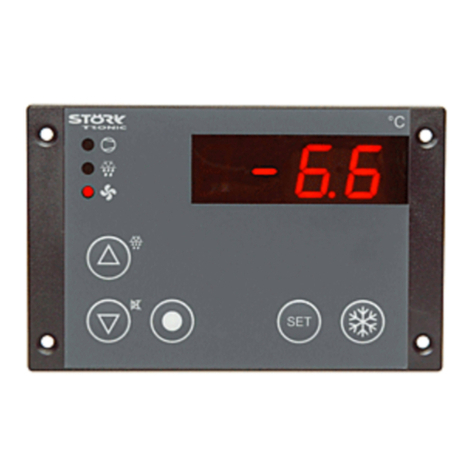
STORK TRONIC ST181-VL4KA.12 User manual

ST181-VL4KA.12
Controller for cooling applications
Order number 900223.015
Old Id.Nr.: 377416
Wiring diagram
Product description
The cooling controller ST181-VL4KA.12 is a control unit specifically designed for 24V DC ven-
tilation adjustment. The maximum ventilation power is 10W. The number of revolutions can be
decreased to 20% and thus create a minimum air speed. Due to the galvanic separation of the
ST181-controller the low-voltage ventilator can also be safely operated in a wet environment.
Thethreeswitchingoutputswithourproven16Arelayallowcompleteoperationofthecoolingcircle
as well as further additional features, as for example the lighting and many other functions.The
timer allows a 1-week time management for the defrosting periods as well as for setting the cooling
chambertemperature at nightor onthe weekend.With regard to the parameterlevel,programming
of this timer is easy and user-friendly. The actual time can be re-set simply directly on the operator
surface.
Sensor: PTC
Range: -55...130◦C
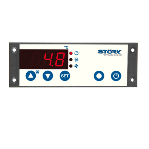
Front size: 180mm x 52mm
Panel cut-out: 159mm x 45mm
1

Tightness: front IP65
Connector: Wieland terminal
2

SOFTWARE .12
Adjustment options
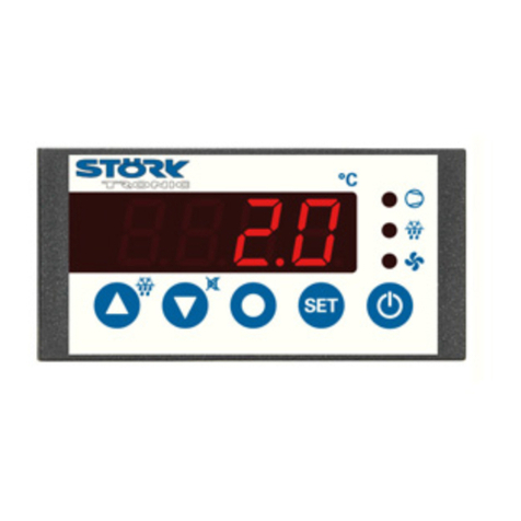
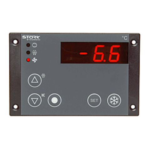
Key UP
Defrosting can be started any time by pressing the UP-key for 3 seconds. During the
process of defrosting the respective LED is illuminated. The LED flashes if defrosting is
requested, but may not be started yet due to interlock conditions.
Key DOWN
The DOWN key, among other functions, can acknowledge an alarm. The internal buzzer
is then switched off.
Press this key more than 5 seconds to switch the display to permanent time indication.
Press the SET key to switch back to temperature indication.
Function key 4 (time)
By pressing this key the actual time of the internal real time clock is indicated in the
display. The colon of the time display flashes. Pressing also the UP or DOWN key at the
same time the clock can be adjusted. With the first adjustment the flashing stops and
after releasing the key the new value is saved. For precise adjustment, hold the key
pressed until a specific time and release it to start.
Pressing the key for 5 seconds the switch-over to data record 2 is deactivated for the
actual day. This is indicated by a flashing point on the right side of the display.
The data record switch-over can be deactivated permanently by parameter H0.
Key SET
While SET key is pressed, the setpoint is indicated.
In addition, the SET key is used for setting parameters.
Function key 1 (if available)
Different functions are assigned to this key by help of parameters, see parameter b1.
It is pre-set for data record switch-over (together with key UP or DOWN).
Function key 2
Different functions are assigned to this key by help of parameters, see parameter b2.
(Direct switching of a contact, setpoint indication thermostat 2). The key must be
pressed for at least half a second.
Function key 3 (standby)
With this key the controller is switched to standby mode. Pressing the key a second
time, restarts the unit. The key can be deactivated by setting the respective parameter,
see parameter b3.

First control level:
Parameter setting for the main setpoint.
If none of the keys is pressed, the display indicates the actual value of the temperature. Pressing
the SET key, the setpoint shows on the display.
If the setpoint is to be changed, the SET key is to be kept pressed while adjusting the setpoint with
the keys UP and DOWN.
Please note that the setpoint can only be changed within the set setpoint limits.
General reference
Note that the value is transferred to the captive memory and is safe also after power failure.
Para-
meter Function Adjustment range Standard
setting Customer
setting
S1 Setpoint for refrigerating
chamber, data record 1 r1...r2 0.0°C
S2 Setpoint for refrigerating
chamber, data record 2 r1...r2 0.0°C
Second control level:
Setting of control parameters
The parameters can also be set in standby mode. Simultaneously pressing the UP and DOWN key
for at least 4 seconds opens a parameter list containing frequently used parameters (the complete
list of all parameters is to be found on the third control level).
With the UP and DOWN keys the list can be scrolled in both directions.
Pressing the SET key will give you the value of the respective parameter. Pressing also the UP or
DOWN key at the same time the value can be adjusted.
Return to the initial position takes place automatically, if no key is pressed for 45 seconds, or by
simultaneously pressing the UP and DOWN key for approx. 4 seconds.
Para-
meter Function Adjustment range Standard
setting Customer
setting
r0 Hysteresis for the compressor
contact 1...15 K 2 K
P2 Indication actual value of
sensor F2
(only available if P4≠0)
-
Y1 Setpoint thermostat 2
(only available if P4=2) -50...+150°C 10°K
Y2 Hysteresis for thermostat 2
(only available if P4=2) 0,5...15 K 2 K
H0 Activation of data record 2 0: not active
1: active depending on
switching time
0
H2 Display manual reset at data
record 2 0: flashing point if key
pressed
1: flashing point until end
of day
0

Para-
meter Function Adjustment range Standard
setting Customer
setting
H11 Time to switch to data record
2, Monday 0:00...23:59 0:00
H12 Time to switch to data record
1, Monday 0:00...23:59 0:00
H21 see H11, Tuesday 0:00...23:59 0:00
H22 see H12, Tuesday 0:00...23:59 0:00
H21 see H11, Wednesday 0:00...23:59 0:00
H22 see H12, Wednesday 0:00...23:59 0:00
H21 see H11, Thursday 0:00...23:59 0:00
H22 see H12, Thursday 0:00...23:59 0:00
H21 see H11, Friday 0:00...23:59 0:00
H22 see H12, Friday 0:00...23:59 0:00
H21 see H11, Saturday 0:00...23:59 0:00
H22 see H12, Saturday 0:00...23:59 0:00
H21 see H11, Sunday 0:00...23:59 0:00
H22 see H12, Sunday 0:00...23:59 0:00
H81 Starting time 1. defrost, daily 0:00...23:59 0:00
H82 Starting time 2. defrost, daily 0:00...23:59 0:00
H83 Starting time 3. defrost, daily 0:00...23:59 0:00
H84 Starting time 4. defrost, daily 0:00...23:59 0:00
H85 Starting time 5. defrost, daily 0:00...23:59 0:00
PA Access to parameters of third
control level
Password: "-19"
-99...+99
Programming cycle for switching times
Selection and adjustment:
By pressing the function key 4 after selection of the parameter to be adjusted, the respective
switch-time is indicated and can be set by additionally pressing the UP or DOWN key. Releasing
all keys, the new value is saved long term.
The parameters with odd numbers always determine the switch-over to data record 2, the following
parameters with even numbers determine the switch-back to data record 1. The leading number of
the parameter symbolizes the weekday, staring with “1” for Monday.
Within the group Defrost (H81 –H85) one can adjust five start times valid for all days. This groups
is symbolized by the leading number “8” in the parameter number.
The programming is analogue to a mechanic timer switch, where a marker for switch-on and one
for switch-off times can be set daily. Note that there is no switching if the adjusted switch-on and
switch-off times of an output are the same on the same day. A cross-over of the time values of a
contact is possible, but the respective times then are ineffective.
Between 23:59 and 0:00 there is the special position “----“. With this setting the respective time is
deactivated and has no more influence on the according switching output. This setting is used to
allow outputs to be switched on for several days.
Third control level (all parameters):
Setting of control parameters
Access to the third control level is granted when selecting parameter PA on the second control
level. Parameter PA is to be set at '-19'. Then the key UP and DOWN have to be simultaneously
pressed for approx. 4 seconds which will give access to the third control level, beginning with
parameter P0. With the keys UP and DOWN you can scroll the list in both directions. Pressing the
SET key will give you the value of the respective parameter. By pressing the UP or DOWN key at
the same time the value can be adjusted.
Return to the initial position takes place automatically, if no key is pressed for 60 seconds, or by
simultaneously pressing the UP and DOWN key for approx. 4 seconds.
Para-
meter Function Adjustment range Standard
setting Customer
setting
P0 Indication of actual value of
sensor F1
P1 Calibration sensor F1,
actual value correction -99...+99 K 0.0 K
P2 Indication of actual value of
sensor F2
(only available if P4≠0)
P3 Calibration sensor F2,
actual value correction
(only available if P4≠0)
-99...+99 K 0.0 K
P4 Evaluation of sensor F2 0: not evaluated
1: evaluated as evaporator sensor
2: evaluated as actual value
thermostat 2
1
P5 Indication mode 0: integrals
1: accuracy 0,5 °C
2: accuracy 0,1 °C
1
P6 Display unit, indication in
standby mode 0: Fahrenheit (“AUS”)
1: Celsius (“AUS”)
2: Fahrenheit (“OFF”)
3: Celsius (“OFF”)
1
P7 Sensor type
(applies to both sensors) 11: Pt100 2-wire
21: PTC 2-wire
22: PT1000 2-wire
21
P8 Software filter
(applies to both sensors) 1: not active
2…32:
average value with 2…32
measuring values
8
P9 Weighing factor measuring
value (data record 1) 0..100 [%] 100
P9 Weighing factor measuring
value (data record 2) 0..100 [%] 100
r0 Hysteresis for the compressor
contact 1...15 K 2 K
r1 Setpoint limitation (minimum) -50 °C...r2 -50 °C
r2 Setpoint limitation (maximum)
r1...+150 °C 50 °C
c0 Start protection of the
compressor after "cooling on"
0...240 min. 0 min.
c1 Start protection after
compressor start 0...240 min. 5 min.

Para-
meter Function Adjustment range Standard
setting Customer
setting
c2 Start protection after
compressor stop 0...240 min. 3 min.
c3 Function in the case of error
of sensor F1
0: relay off
1: relay on
2: emergency operation
0
d0 Defrosting interval 0 = inactive, no defrosting
1...99 h
8 h
d1 Defrosting mode 0: electrical
1: with hot gas 0
d2 Defrosting temperature -50...+150 °C 10 °C
d3 Defrosting time limit 1...99 min. 30 min.
d6 Indication of the refrigerating
chamber temperature during
defrosting
0: actual temperature
1: temperature determined just
before the start of defrosting
1
d7 Drainage time 0...15 min. 2 min.
A0 Hysteresis for alarm 1...15 K 2 K
A1 Minimum limit value -99.0 ... -0.1 K
0 = inactive -10 K
A2 Maximum limit value +0.1...+99.0 K
0 = inactive 10 K
A3 Alarm suppression time after
“cooling on” 0...240 min. 120 min.
A6 Alarm suppression time after
temperature alarm 0...240 min. 2 min.
A7 Alarm suppression time after
defrosting 0...240 min 15 min.
A9 Switching sense alarm
contact 0: relay on
1: relay off
1
F4 Defrosting behaviour 0: ventilator off during defrosting
1: ventilator on during defrosting
1
F5 Ventilator delay after
defrosting 0...240 min. 2 min.
F7 Ventilator function at cooling
operation 1: always on
2: on or off together with the
compressor
3: on whenever the compressor is
on and sensor F2 < sensor F1
2
F8 Ventilator revolution number
(data record 1) at normal
cooling operation
0..100% 80
F9 Ventilator revolution number
(data record 1) at defrosting 0..100% 80
F10 Kick-start 0..60s 0
F11 Ventilator revolution number
(data record 2) at normal
cooling operation
0..100% 80
F12 Ventilator revolution number
(data record 2) at defrosting 0..100% 80
Y0 Indication mode of the actual
value of sensor F2 0: with parameter P2
1: with DOWN key 0
Y1 Setpoint thermostat 2
(only available if P4=2) -50...+150°C 10°C

Para-
meter Function Adjustment range Standard
setting Customer
setting
Y2 Hysteresis for thermostat 2
(only available if P4=2) 0,5...15 K 2 K
Y3 Setpoint limitation (minimum)
thermostat 2 -50°C...Y4 -50 °C
Y4 Setpoint limitation (maximum)
thermostat 2 Y3...150°C+50 °C
Y5 Switch mode thermostat 2 0: heating contact
1: cooling contact
1
Y6 Function in case of error of
sensor F2 0: relay off
1: relay on
1
Y7 Defrosting interval
thermostat 2 0: inactive, no defrosting
1...99 h 0
Y8 Defrosting time limit
thermostat 2 1...99 min
0: inactive 30 min.
b1 Function key 1
(if available) 0: no function
1: controller on/off (standby)
2: Setpoint ventilator revolution
number (F8/F11)
3: relay directly, switched off in
standby mode
4: relay directly, regardless of
standby mode
5: actual value sensor F2
6: switching data record 1 and 2;
after power-on data record 1 is
active
7: like 6, after power-on last data
record is active
8: Setpoint Y1
6
b2 Function key 2 see b1 0
b3 Function key 3 (standby) 0: no function
1: controller on/off (standby)
1
b4 Function key 4 (if available) TIME-key (in case of controllers
with RTC) or else like b1
b11 Function switching input E1
(if available) 0: no function
1: controller on/off (standby)
2: starting defrost
3: relay directly, switched off in
standby mode
4: relay directly, regardless of
standby mode
0
b12 Function switching input E2
(if available) see b11 0
b13 Function switching input E3
(if available) see b11 0
b14 Function switching input E4
(if available) see b11 0

Para-
meter Function Adjustment range Standard
setting Customer
setting
U1 Exit connection K1 0: no connection
1: connection to compressor
2: connection to defrost
3: connection to ventilator
4: connection to alarm
5: connection to thermostat 2
6: connection to function key 1,
E1 or E3
7: connection to function key 2,
E2 or E4
8: connection to buzzer
9: on, if controller on
10: on, if data record 2 is activated
(operates as timer switch)
1
U2 Exit connection K2 see U1 2
U3 Exit connection K3
(or internal buzzer, if
available)
see U1 3
U4 Exit connection K4
(if available) see U1 4
L0 Individual address 0 = inactive for Bus
1...255
0
L1 Amount of slaves
(if value > 0 the controller is
set as master automatically)
0...254 0
L2 Address of the first slave
(only relevant if L1>0) 2...255 2
Pro Program version

Parameter description:
The following values can change the equipment characteristics
and are therefore to be set with utmost care.
P0: Indication actual value of sensor F1
The here indicated temperature presents the sum of actual measured value of feeler F1 and the
actual value correction according to parameter P1.
P1: Calibration sensor F1, actual value correction
This parameter allows the correction of actual value deviations caused for example by sensor
tolerances or extremely long sensor lines. The regulation measure value is increased or decreased
by the here adjusted value.
P2: Indication actual value of sensor F2
The here indicated temperature presents the sum of actual measured value of sensor F2 and the
actual value correction according parameter P3.
P3: Calibration sensor F2, actual value correction
This parameter allows the correction of actual value deviations caused for example by sensor
tolerances or extremely long sensor lines. The regulation measure value is increased or decreased
by the here adjusted value.
P4: Evaluation of sensor F2
Sensor F2 can be used for the determination of the evaporator temperature (P4=1) or for the
second thermostat (P4=2).
If, in simpler refrigerant plants only the refrigerating chamber sensor is used, the feeler entrance for
sensor F2 as well as its data recording (P4=0) can be deactivated here. Among other, parameter
d2 has no meaning in the deactivated condition.
P5: Indication mode
The actual value can be indicated with different accuracy.
Actual values and parameter values are always set for highest accuracy.
P6: Display unit, indication in standby mode
This parameter allows display settings (°F or °C) and ("AUS" or "OFF") in standby mode.
P7: Sensor type
This parameter makes it is possible to adjust the feeler type of both sensors. Depending on the
hardware not all sensor settings are possible.
P8: Filter
This parameter can determine by how many measured values an average value is to be formed.
P9: Weighing factor for measuring value of refrigerating chamber sensor F1 (data record 1)
P10: Weighing factor for measuring value of refrigerating chamber sensor F1 (data record 2)
The actual value of the respective data record can be submitted to weighing. In this case the actual
value is formed by a mixing ratio of the measuring values of sensor F1 and F2. (new function of the
sensors as supply-air and exhaust-air sensor).
At standard setting [P9 = 100%] the actual value corresponds to the refrigerating chamber sensor.
As soon as parameter P9 differs from 100% the measuring values are submitted to weighing.
The actual value then is formed as followed:
Actual value = (P9 * measuring value F1 + (100 –P9) * measuring value F2) / 100%
F1 = refrigerating chamber sensor / supply air
F2 = evaporator sensor / exhaust air

The weighing is only effective, if the sensor F2 is evaluated as evaporator sensor with parameter
P4. For the defrost control the not weighed value of sensor F2 is effective.
r0: Hysteresis for the compressor contact
Parameter r0 sets the temperature margin between switching off and switching on of the
compressor. A small hysteresis permits a more exact regulation, however also leads to more
frequent switching of the compressor. The hysteresis is set one-sided above the setpoint.
r1: Setpoint limitation (minimum)
r2: Setpoint limitation (maximum)
These parameters limit the adjustment range of the setpoint S1, in order to avoid that the end user
sets inadmissible values for the plant.
The entire adjustment range is equivalent to the maximum operating range of a PTC sensor.
c0: Start protection of the compressor after "cooling on"
After cooling is switched on (e.g. by switching on the mains voltage) the start of the compressor is
retarded until the protection running time is over. This secures e.g. that several cooling units do not
start at the same time and load the electricity supply net.
c1: Start protection of the compressor after compressor start
This time protection starts when the compressor is switched on. After switching the compressor off,
a renewed switching on is impossible until this protection time runs out. This prevents from too
frequent switching-on of the compressor and thus increases its life span.
c2: Start protection of the compressor after compressor stop
This time protection starts when the compressor is switched off. After switching the compressor off,
a renewed switching on is impossible until this protection time runs out.
c3: Function in the case of error of refrigerating chamber sensor F1
Here is determined whether the compressor keeps running or not in the case of an error of the
refrigerating chamber feeler F1. When deep-freezing, the compressor should normally continue
running, in order to prevent de-frosting of the goods. At the normal cooling range above 0 °C, a
continuation, however, could lead to frost damages.
In the operation mode "emergency operation" the compressor is switched on and off in 5 minute
intervals. This results in a clock operation with 50 % cooling performance.
d0: Defrosting interval
The defrosting interval defines the time, after which a defrosting process is started. With the
beginning of the defrosting process, the defrosting interval starts anew, which results in periodic
defrosting in firm intervals.
Defrosting can also be started by pressing the key "manual defrosting" for at least 3 seconds. This
automatically restarts the defrosting interval.
After switching-on cooling, the controller immediately initiates cooling and starts the first defrosting
process after this interval.
d1: Defrosting mode
This parameter determines whether defrosting is effected by an electrical heating coil (d1=0) or by
means of hot gas (d1=1).
d2: Defrosting temperature
The defrosting process is terminated when the evaporator has reached the adjusted temperature.
(Always provide good thermal contact between evaporator sensors and lamellas).
In case that defrosting takes too long, the time limit set in "d3" will come into effect.

d3: Defrosting time limit
Here the maximal defrosting time can be adjusted. According to this time frame, defrosting is
terminated even if the evaporator is not warm enough to be ice-free.
d6: Indication of the refrigerating chamber temperature during defrosting
It is to be assumed that the refrigerating chamber temperature slightly rises during the defrosting
process. d6=0 indicates the actual refrigerating chamber temperature during the defrosting
process. d6=1 indicates the temperature determined just before the start of defrosting until the
setpoint of the refrigerating chamber is reached again after the defrosting process is completed.
Thus, an irritation of the operator during defrosting can be avoided. In the case of emergency, the
display flashes and the actual temperature of the refrigerating chamber is indicated.
d7: Drainage time
Completed defrosting is immediately followed by a drainage period, in order to let the evaporator
drip off. During drainage time, the exits compressor and ventilator are switched off.
A0: Switching hysteresis for alarm
The hysteresis of the alarm contact is asymmetrically, set downward at the maximum alarm value
upward at the minimum alarm value.
A1/A2: Minimum/maximum limit values
The limit values serve for monitoring of the refrigerating chamber temperature. They are relative,
i.e. going along with the setpoint S1 of the refrigerating chamber. Alarm is released when
exceeding maximum limit value or when falling below the minimum limit value:
The actual value display flashes, the buzzer (if available) goes off intermittently and the actual
temperature of sensor F1 is indicated (if there is no sensor error).
At A1=0 or A2=0 the respective limit value alarm is inactive.
The buzzer can be turned off with the DOWN key, the display continues flashing until the alarm is
turned off.
A3: Alarm suppression time after “cooling on” or data record switch-over
After switching cooling on or a data record switch-over, an alarm is suppressed for the adjusted
time, i.e. the refrigerant plant can get to work temperature without releasing alarm.
A6: Alarm suppression time after temperature alarm
If the refrigerating chamber temperature exceeds the limit values adjusted at A1, A2, normally a
temperature alarm should be released.
With the suppression time set at A6 the alarm release can be delayed.
A7: Alarm suppression time after defrosting
Temperature alarm is avoided for the adjusted time after defrosting, in order to enable the plant to
get back to the normal operating conditions (see A1, A2).
A9: Switching sense alarm exit
Depending on application, the alarm exit requires a normally-closed or a normally-open contact. At
setting A9=1 the relay tightens in normal operation and opens in the case of emergency. That way
also a voltage failure of the controller can be detected (relay dead = alarm) for an external alarm
chain.
F4: Defrosting behaviour
At F4=0 the ventilator is switched off during defrosting.
At F4=1 the ventilator continues to run also during defrosting (normal cooling range above 0°C).
F5: Ventilator delay after defrosting
Following drainage time d7, start of the ventilator can be delayed until the evaporator has
sufficiently cold air again. If the ventilator started immediately, the warm air resulting from the

defrosting process would probably be blown into the refrigerating chamber. The ventilator delay is
ineffective if the ventilator is on during defrosting and the drainage time is set to “0”.
F7: Ventilator function at cooling operation
At F7=1 the ventilator is always on (except for a defrosting process possibly, see parameter F4).
At F7=2 the ventilator is always on or off together with the compressor.
At F7=3 the ventilator is switched on whenever the compressor is on and the evaporator
temperature (sensor F2) is below the refrigerating chamber temperature (sensor F1). The ventilator
is switched off whenever the compressor is switched off, whereas parameter F5 is not active. In
the case of sensor error the ventilator reacts as in the setting F7=2.
F8: Ventilator revolution number (data record 1) at normal cooling operation
Variable 1 for ventilator revolution number at normal cooling operation.
F9: Ventilator revolution number (data record 1) at defrosting
Variable 1 for ventilator revolution number at defrosting.
F10: Kick-start (in seconds)
If necessary, this is an option to set a time during which the ventilator starts with the max. number
of revolutions for stable operation. This parameter is only efficient, if the ventilator is newly started.
F11: Ventilator revolution number (data record 2) at normal cooling operation
Variable 2 for ventilator revolution number at normal cooling operation.
F12: Ventilator revolution number (data record 2) at defrosting
Variable 2 for ventilator revolution number at defrosting.
Y0: Indication mode of the actual value of sensor F2
At Y0=0 the actual value of sensor F1 is always indicated. The actual value of sensor P2 can be
indicated with parameter P2 (second control level).
At Y0=1 the actual value of sensor F2 is indicated when pressing the DOWN key.
Y1: Setpoint thermostat 2
In case that sensor 2 is not used as evaporator sensor, but as actual value for a second
independent thermostat, Y1 has the function of setting the setpoint for the latter. If parameters of a
function key are set appropriately (parameter bx=2), the setpoint can also be adjusted directly with
the respective function key.
Y2: Hysteresis thermostat 2
The hysteresis is set asymmetrically at the desired value. At cooling contact the hysteresis works
on one-sided upward and at heating contact one-sided downward.
Y3/Y4: Setpoint limitation (maximum/minimum) thermostat 2
These parameters limit the adjustment range of the desired value Y1, in order to avoid that the end
user sets inadmissible values for the plant. The entire adjustment range is equivalent to the
maximum work range of the PTC sensor.
Y5: Switch mode for the exit of thermostat 2
Heating function means that the contact falls when the pre-set desired value is reached, i.e. power
interruption. In cooling functions the contact only tightens if the actual value is above the pre-set
setpoint.
Y6: Function at error of sensor F2
Here is determined whether the respective output contact drops or tightens in case of a sensor F2
error.

Y7: Defrosting interval thermostat 2
The defrosting interval defines the time, after which each defrosting process starts. With the
beginning of the defrosting process, the defrosting interval starts anew, which results in the
periodic defrosting in firm intervals.
Y8: Defrosting time limit thermostat 2
Here the maximal defrosting time can be set.
b1: Function key 1 (if available)
b2: Function key 2
b4: Function key 4 (if available and not foreseen as TIME key)
At setting = 0 the respective key has no function.
At setting = 1 the controller is switched to standby mode
At setting = 2 the key is linked with the function of parameter F8 or F11 (depending on active data
record). If defrosting has started it is linked with parameters F9 or F12.
At setting = 3 a relay (indicated with parameter Ux) can be switched on or off directly with the key.
In standby mode the key is locked and the corresponding relay switched off. After restarting the
corresponding relay remains switched off.
At setting = 4 a relay (indicated with parameter Ux) is switched despite of the standby mode. The
condition of the exit is maintained until the key is pressed again or until it is changed by an external
switching entrance. After net interruption, the condition before power failure is re-installed.
At setting = 5 the actual value of sensor 2 can be indicated. At setting P4=0 the key has no
function.
At setting = 6 the control is switched to data record 1 by additionally pressing the UP key and
switched to data record 2 with the DOWN key. The data record switches the following parameters:
Description Data record 1
Data record 2
Setpoint S1 S2
Revolution number
cooling operation F8 F11
Revolution number
defrosting F9 F12
The actual setpoint can be displayed and adjusted by pressing the SET key. If only the ventilator
revolution number has to be adjusted both data records must have the same setpoint.
Setting =7 corresponds to setting=6 but when switching the controller on the previous selected
data record is active. Exception: If the controller is equipped with a real time clock, the clock sets
the active data record after switching on (if H0=1 and parameters H11…H72 activated).
b3: Function key 3 (standby)
At setting b3=0 the function of the key can be deactivated.
b11: Function external entrance E1
b12: Function external entrance E2
b13: Function external entrance E3
b14: Function external entrance E4
Depending on existing hardware there are no or not all external entrances.
At setting = 1 the controller is switched to the standby mode.
At setting = 2 defrosting of both controllers is started.
At setting = 3 a relay (indicated with parameter Ux) is switched on or off directly. In standby mode it
is locked and the relay is switched off.
At setting = 4 a relay is switched directly (indicated with parameter Ux) regardless of the standby
mode. After net interruption the condition before power failure is re-installed.

U1: Exit connection K1
U2: Exit connection K2
U3: Exit connection K3
U4: Exit connection K4
Depending on existing hardware there may not be all output relays. This parameter assigns the
respective relay to the internal controller exits, to function key 1 or 2, to one external entrance or
the buzzer.
At setting =6 or =7 the relay is switched manually. It changes its condition with each pressure of
the key and adopts the condition of the respective switching entrance whenever the latter changes.
If the corresponding key or switching entrance has not been released for this function (see
parameters b1, b2 and b11 to b14), the relay remains switched off.
The buzzer connection in its function is comparable to the alarm connection. The buzzer, however,
can be switched off with the DOWN key.
L0: Individual address
L1: Amount of slaves
L2: Address of the first slave (if L1>0)
Parameters of the interface. If L1>0 the controller is set as master automatically. The slaves react
to the instructions of the master (defrosting, switching data record 1/2, status messages).
Pro: Program version
This parameter shows the program version.
Additional notes for adjusting parameters
Some parameter adjustments are not effective at once. I.e. if the alarm suppression time is
decreased from 120 to 10 minutes the new value is only effective at the following alarm. If the
controller is shortly separated from the net the new values will be effective immediately.
Network behaviour
Via PC it is possible to read and write parameters from or to the controller. For this purpose the
Gateway box of Störk-Tronic is required which converts the signal of the RS232 to RS485.
If defrosting is started by means of the RTC, a corresponding defrost command is sent to the
network members.
The data record switch-over is sent each time.
Starting behaviour
If the controller is equipped with a real time clock the programmed times (H11-H72) will be
checked and the respective data record will be set accordingly after switching on the unit.
To achieve this it is required that parameter H0=1 and that the times make sense, i.e. they are not
deactivated (display indicates “---“) or all times are set to the same value (i.e. 00:00).
If the data record cannot be determined by means of the real time clock, parameters b1 and b2
control the starting behaviour. If b1=6 and b2=6 data record 1 is active. If b1=7 or b2=7 the
previously selected data record is active.
Approx. 5 seconds after switching on the controller, the data record is submitted to other members
via network, if parameter L1>0.

Status messages
Message Cause Error elimination
ON/OFF Standby modus, no regulation Switch on by key or switching input
Temperature
indication flashes Refrigerating chamber temperature
beyond alarm limits (parameter A1, A2)
E0
flashes Refrigerating chamber sensor F1 error,
break or short-circuit Control sensor. Controller operates
according to with parameter c3.
E1
flashes Sensor F2 error,
break or short-circuit Control sensor.
At setting [c3=1] the controller
operates in timed defrosting modus
(defrosting time as set in d3).
At setting [c3=2] see parameter Y6.
"rC", flashing Data loss real time clock Adjustment of the clock
"rF", flashing Error real time clock If error cannot be eliminated by
switching on/off, the controller must
be repaired.
EP Data loss at parameter memory (basic
contact 1 and 2 are dead) If error cannot be eliminated by
switching on/off, the controller must
be repaired.
Error message E0, E1, EP and rC change in the display with the actual value of sensor F1, unless
the latter is defective. This happens independently from the selected indication mode. After the
error is eliminated and confirmed with the DOWN key, the previously set indication mode becomes
active again.
If there is a connection to the buzzer with parameters U1... U4, the buzzer can be switched off with
the DOWN key.

Order No.: 377416
Technical data of ST181-VL4KA.12
Measuring input
F1: Temperature sensor PTC, refrigerating chamber
F2: Temperature sensor PTC for defrosting, evaporator surface
Measuring range: PTC (KTY81-121) -50°C...+130°C
Measuring accuracy: ±0,5K ± 0,5 % at 25°C, without sensor
±1K ± 0,5 % of scale range (0 – +55°C), without sensor
Outputs
K1: Relay, 30(6)A 250V~, normally-open contact, function see U1
permanent current max. 16(6)A, limited by connectors and/or conductive strips
K2: Relay, 16(2,2)A 250V~, normally-open contact, function see U2
K3: Relay, 16(2,2)A 250V~, normally-open contact, function see U3
S1: Voltage output for DC-Fan: 0..24V, max. 420mA (corresponds 10W)
Additional buzzer, 85dB
Display
One 3-digit LED-display, 13 mm height, for temperature indication
Three LEDs for status of the outputs compressor, defrosting and fan
Two LEDs for indication of the active data record
7 LEDs for the week timer
Power supply
230 V 50/60 Hz, Power consumption max. 4 VA
Connectors
Wieland terminal
Ambient conditions
Storage temperature: –20°C...+70°C
Operating temperature: 0...55°C
Relative humidity: max. 75 %, without dew
Weight
ca. 520g, without sensor
Enclosure
Front IP65, IP00 back (unit is open on backside)
Installation data
The unit is foreseen to be installed in an instrument panel.
Front size: 180 x 52 mm
Panel cut-out: 159 x 45 mm
Installation depth: ca. 165mm with connectors
Table of contents
Other STORK TRONIC Controllers manuals

STORK TRONIC
STORK TRONIC ST96 Series Quick start guide

STORK TRONIC
STORK TRONIC ST501 Series Quick start guide

STORK TRONIC
STORK TRONIC ST501-KU3KA.12P User manual

STORK TRONIC
STORK TRONIC ST181-LM4KAR.112 User manual

STORK TRONIC
STORK TRONIC ST552 Glass User manual

STORK TRONIC
STORK TRONIC ST603-QN1LAR.112 Quick start guide

STORK TRONIC
STORK TRONIC ST710-KPLVR.112S Quick start guide

STORK TRONIC
STORK TRONIC ST501-JX1TA User manual

STORK TRONIC
STORK TRONIC ST189-XRTUR.209 User manual

STORK TRONIC
STORK TRONIC ST121-KD1KAR.112 User manual