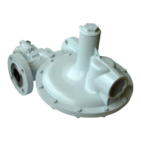
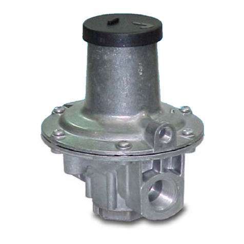
Elster J48Z Training manual

J48Z and P
Zero Regulator and
Proportionator
Commissioning Instructions
General Arrangement
Parts List
Maintenance Instructions
For: J48Z Zero Regulator ¾" - 2"
J48P Proportionator ¾" - 2"
This product is discontinued!

2
J
48Z and P: Commissioning Instructions
OPERATING INSTRUCTIONS
•Ensure that this product is suitable for the chosen application.
•Installation, adjustment and maintenance by authorised, trained
personnel only.
•When being fitted to an appliance, refer to the appliance
manufacturers instructions.
•The unit should not be installed in a corrosive environment.
•The ambient temperature (surface temperature) should be within the
limits stated on the regulator catalogue.
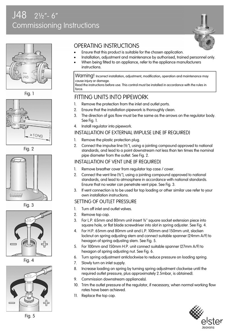
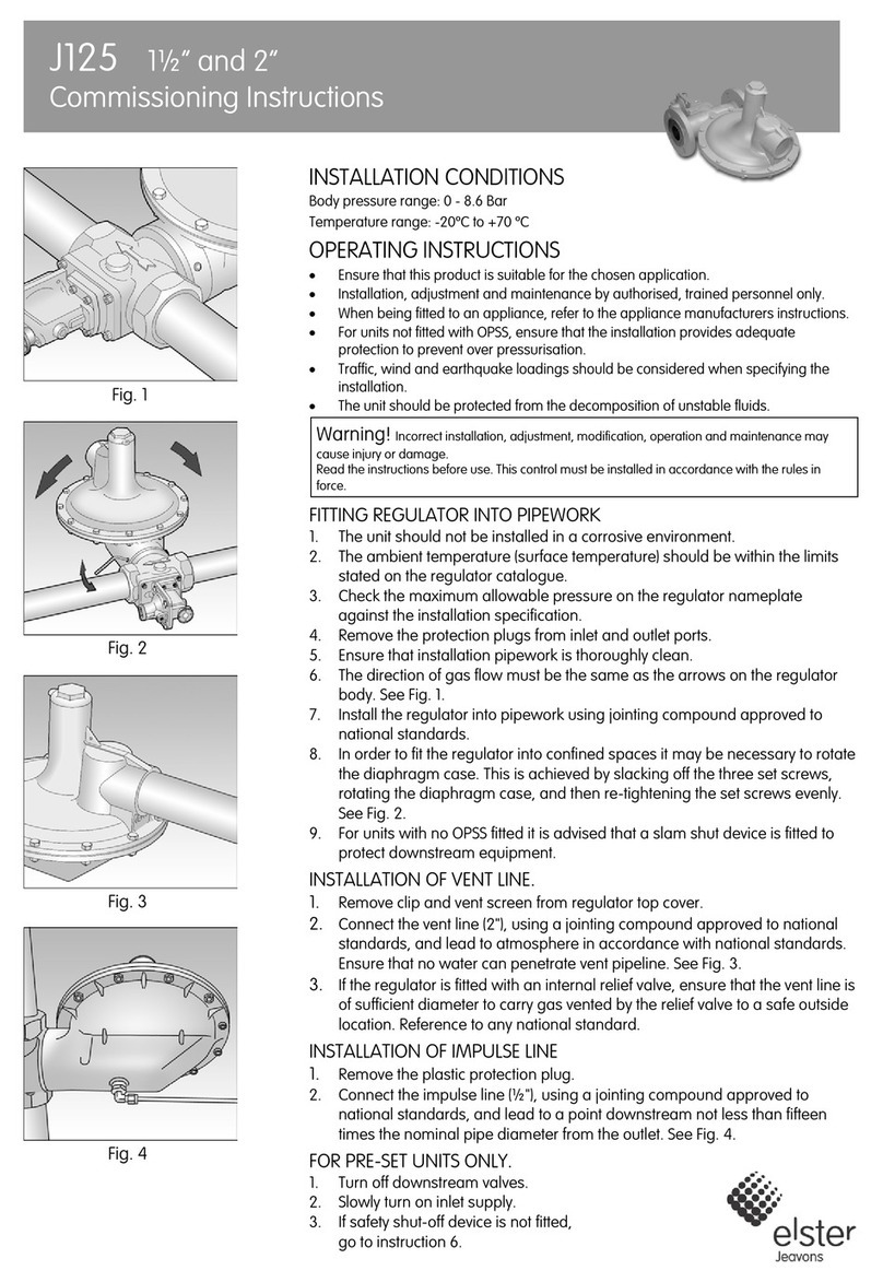
FITTING UNIT INTO PIPEWORK (A)
1. Remove the plastic protection plugs from inlet, outlet and impulse.
2. Ensure that installation pipework is thoroughly clean.
3. The direction of gas flow must be the same as the arrow(s) on the unit
body.
4. Install the unit into horizontal pipework with the spring housing
pointing vertically downwards. Use a jointing compound approved to
national standards.
INSTALLATION OF AIR CONTROL LINE (B) IF REQUIRED
1. Remove the plastic protection plug.
2. Connect the air control line (Rc1/4 connection), using a jointing
compound approved to national standards. Connection of air line will
depend upon the specification of the overall installation.
ADJUSTMENT OF OUTLET PRESSURE (C).
1. Small changes to the outlet pressure can be made by removing the
cap at the base of the spring housing and turning the spring
adjusting screw clockwise to increase pressure or anticlockwise to
reduce the outlet pressure.
2. Replace the cap (and seal if necessary).
Warning! Incorrect installation, adjustment, modification, operation
and maintenance may cause injury or damage.
Read the instructions before use. This control must be installed in
accordance with the rules in force.

3

4
J48Z and P: General Arrangement
All sizes
24
37
19
20
21
22
23
14
35
16
31
36
13
11
18
15
Spring Adjustment
Pre October 2000
For all 1¼” – 2” units, and ¾” – 1” units fitted with Compression Spring
(from October 1997)
1
7
6
5
4
3
2
12
33
9
10
8
34
38

5
J
48Z and P: General Arrangement
For all ¾” & 1” units fitted with Tension Spring
(up to September 1997)
12
11
9
10
8
7
6
5
4
3
2
1
13
14
15
16
25
18
26
20
21
22
23
24

6
J48Z and P: Parts List
¾” and 1” sizes
ITEM DESCRIPTION ¾” No. Off 1” No. Off
1 BOTTOM PLUG J4806-017Z03 1 J4806-017Z03 1
2 BODY J4805-005+ 1 J4806-094+ 1
3 VALVE DISC HOLDER J4806-015 1 J4806-015 1
4 VALVE DISC J4806-025 Ï1 J4806-025 Ï1
5 VALVE SPACER J4806-014 1 J4806-014 1
6 DIAPHRAGM SPACER J4806-018 1 J4806-018 1
7 MAIN DIAPHRAGM J4806-011 Ï1 J4806-011 Ï1
8 SCREW JSA520XPTZ 6 JSA520XPTZ 6
9 NAMEPLATE J8112-124 1 J8112-124 1
10 TOP COVER J4806-103+ 1 J4806-103+ 1
11 TOP SPRING HOLDER (Course thread) J4806-098 1 J4806-098 1
12 TOP CAP J4806-099 1 J4806-099 1
13 LOCKING LEVER J4806-105 1 J4806-105 1
14 “O” RING SEAL JO200032-4475 Ï1 JO200032-4475 Ï1
15 ADJUSTMENT BUSH (Old Design) J4806-100 1 J4806-100 1
16 “O” RING SEAL JORM0051-16 Ï1 JORM0051-16 Ï1
18 SPRING ADJUSTING SCREW (Course thread) J4806-097 1 J4806-097 1
19 VALVE SPINDLE JSA440IPNZ 1 JSA440IPNZ 1
20 TOP DIAPHRAGM PLATE J4806-003 1 J4806-003 1
21 SCREW JSA410XPTZ 6 JSA410XPTZ 6
22 SECONDARY DIAPHRAGM J4806-095 Ï1 J4806-095 Ï1
23 IMPULSE TUBE J4706-072 J4706-072
24 “O” RING SEAL JORM0376-24 Ï1 JORM0376-24 Ï1
25 TENSION SPRING (To Sept ’97) J4806-106 1 J4806-106 1
26 VALVE SPINDLE (FOR ZERO) (To Sept ’97) J4806-019 1 J4806-019 1
31 LOADING SPRING J4806-125 1 J4806-125 1
32 ORIENTATION LABEL J7806-027 1 J7806-027 1
33 TOP SPRING HOLDER (Fine Thread) J4806-127 1 J4806-127 1
34 WASHER J4806-134 Ï1 J4806-134 Ï1
35 ADJUSTMENT BUSH (New Design) J4806-100Z01 1 J4806-100Z01 1
36 SPRING ADJUSTING SCREW (Fine Thread) J4806-128 1 J4806-128 1
37 CIRCLIP JCIR1500-080Z 1 JCIR1500-080Z 1
38 SEALING WASHER J7706A-044 1 J7706A-044 1

7
J48Z and P: Parts List
1¼”, 1½” and 2” sizes
ITEM DESCRIPTION 1¼” No. Off 1½” No. Off 2” No. Off
1 BOTTOM PLUG J4808-017Z03 1 J4808-017Z03 1 J4809-017Z03 1
2 BODY J4807-011+ 1 J4808-084+ 1 J4809-071+ 1
3 VALVE DISC HOLDER J4808-015 1 J4808-015 1 J4809-015 1
4 VALVE DISC J4808-035 Ï1 J4808-035 Ï1 J4809-027 Ï1
5 VALVE SPACER J4808-014 1 J4808-014 1 J4809-014 1
6 DIAPHRAGM SPACER J4808-021 1 J4808-021 1 J4809-018 1
7 MAIN DIAPHRAGM J4808-011 Ï1 J4808-011 Ï1 J4809-011 Ï1
8 SCREW JSA520XPTZ 8 JSA520XPTZ 8 JSA520XPTZ 8
9 NAMEPLATE J8112-124 1 J8112-124 1 J8112-124 1
10 TOP COVER J4808-078+ 1 J4808-078+ 1 J4809-067+ 1
11 TOP SPRING HOLDER (Course thread) J4806-098 1 J4806-098 1 J4806-098 1
12 TOP CAP J4806-099 1 J4806-099 1 J4806-099 1
13 LOCKING LEVER J4806-105 1 J4806-105 1 J4806-105 1
14 “O” RING SEAL JO200032-4475 Ï1 JO200032-4475 Ï1 JO200032-4475 Ï1
15 ADJUSTMENT BUSH (Old Design) J4806-100 1 J4806-100 1 J4806-100 1
16 “O” RING SEAL JORM0051-16 Ï1 JORM0051-16 Ï1 JORM0051-16 Ï1
18 SPRING ADJUSTING SCREW (Course thread) J4806-097 1 J4806-097 1 J4806-097 1
19 VALVE SPINDLE JBA650HEXZG 1 JBA650HEXZG 1 JBA865HEXZG 1
20 TOP DIAPHRAGM PLATE J4808-003 1 J4808-003 1 J4809-003 1
21 SCREW JSA510XPTZ 6 JSA510XPTZ 6 JSA510XPTZ 8
22 SECONDARY DIAPHRAGM J4808-070 Ï1 J4808-070 Ï1 J4809-070 Ï1
23 IMPULSE TUBE J4808-076 1 J4808-076 1 J4709-060 1
24 “O” RING SEAL JORM0546-24 Ï1 JORM0546-24 Ï1 JORM0745-32 Ï1
31 LOADING SPRING J4806-020 1 J4806-020 1 J4806-020 1
32 ORIENTATION LABEL J7806-027 1 J7806-027 1 J7806-027 1
33 TOP SPRING HOLDER (Fine Thread) J4806-127 1 J4806-127 1 J4806-127 1
34 WASHER J4806-134 Ï1 J4806-134 Ï1 J4806-134 Ï1
35 ADJUSTMENT BUSH (New Design) J4806-100Z01 1 J4806-100Z01 1 J4806-100Z01 1
36 SPRING ADJUSTING SCREW (Fine Thread) J4806-128 1 J4806-128 1 J4806-128 1
37 CIRCLIP JCIR1500-080Z 1 JCIR1500-080Z 1 JCIR1500-080Z 1
38 SEALING WASHER J7706A-044 - J7706A-044 - J7706A-044 -
Note: Part numbers marked + re
q
uire connection thread to be s
p
ecified with order.
SPARES KITS
Spares kit contents are marked Ïon parts list
SPARES KIT CODE SIZE
SK4806-01 ¾” – 1”
SK4808-01 1¼” – 1½”
SK4809-01 2”

8
J48Z and P: Maintenance Instructions
For all units after October 1997
Dismantling Procedure:
1. Pull off top cap (12).
2. Turn spring adjusting screw (44) anti-clockwise (to reduce loading on spring).
3. Carefully lift protruding end of locking lever (13) just above adjusting bush (43) whilst in this position turn (octagon
shaped) adjusting bush (43) assembly anti-clockwise until disengaged. The adjusting bush (43) can then be removed
from the top cover (10).
4. Remove the loading spring (17) from the top cover (10).
NOTE: If adjusting bush assembly is to be dismantled for "O" ring replacement, follow procedure. If to be left assembled
proceed to instruction number 9.
5. Lift keyhole end of locking lever (13) over sloping peg in adjusting bush (43), and slide forward, until disengaged from
spring adjusting screw (44) and remove.
6. Pull spring adjusting screw (44) from adjusting bush (43).
7. Remove "O" rings (16) & (14) from spring adjusting screw (44) and adjusting bush (43) respectively.
8. Lift washer (42) from spring adjusting screw (44) and remove.
9. Remove top cover screws (8) then carefully remove the top cover (10).
10. Unscrew bottom plug (1) and remove from body (2).
10.1 Remove "O" ring (24) from bottom plug (1).
10.2 Restrain valve spindle guide (3) with suitable box spanner and unscrew the valve spindle (19).
10.3 Withdraw the valve spindle guide (3) and valve disc clamping washer (4) through the bottom plug opening.
11. Remove the valve spindle (19).
12. Remove the top diaphragm plate (20).
13. Carefully remove main diaphragm (7).
14. Remove diaphragm spacer (6).
15. Remove secondary diaphragm screws (21).
16. Carefully remove the secondary diaphragm (22).
17. Remove valve spacer (5) and valve disc (23).
18. Remove creep relief assembly (39) (if fitted) clean and inspect for damage.
19. Wipe valve seat and body clean of any dirt particles, taking care not to damage sealing surface in body.
20. Inspect all diaphragms and soft seals and replace where necessary (a spares kit is available for this purpose).

9
Rebuilding procedure:
The use of Molykote 111 "O" ring lubricant is recommended during the rebuild.
1. Locate secondary diaphragm (22) with convolution uppermost on to the body (2). Ensure screw holes and impulse tube
holes are aligned correctly.
2. Secure secondary diaphragm (22) in position using screws (21).
3. Place diaphragm spacer (6) on secondary diaphragm (22) ensuring diaphragm bead is located correctly in the groove.
4. Place main diaphragm (7) with convolution uppermost, ensuring that the bead is located in the groove in the body (2).
5. Locate the top diaphragm plate (20) ensuring raised edge is uppermost.
6. Insert the valve spindle (19) through the centre hole in top diaphragm plate (20), main diaphragm (7) and diaphragm
spacer (6).
7. Locate valve spacer (5) on to valve spindle (19) through bottom plug opening.
8. Assemble valve disc (4) on to valve disc holder (3) with bead uppermost.
9. Screw valve disc holder (3) complete with valve disc (4) on to threaded end of valve spindle (19) through bottom plug
opening. DO NOT TIGHTEN.
10. Restrain valve disc holder (3) with suitable box spanner and tighten valve spindle (19).
11. Place "O" ring seal (24) into "O" ring seal groove in bottom plug (1), outlet adaptor bush (28) or meter union assembly
(29).
12. Replace the component (1), (28) or (29) complete with "O" ring over centre shaft of valve disc holder (3) into body (2) and
screw tightly in position.
13. Carefully replace top cover (10) on to body (2) with vent facing the outlet and secure with top cover screws (8).
14. Insert loading spring (17) over spring location ridge in top diaphragm plate (20).
NOTE: If adjusting bush assembly (35) has been dismantled follow procedure, if it has been left assembled then proceed to
instruction number 21.
15. Slide "O" ring seal (16) over slotted end of spring adjusting screw (36) into second groove. (i.e. groove nearest thread).
16. Replace washer (34) over slotted end of spring adjusting screw (36) and slide down until it sits on shoulder of adjusting
screw.
17. Slide "O" ring seal (14) into "O" ring groove on adjusting bush (35).
18. Push spring adjusting screw (36) into hole in the bottom of the adjusting bush (35) until parts are firmly together.
19. Position key hole slot in locking lever (13) over slotted end of spring adjusting screw (35) and slide over slopping peg in
adjusting bush (35) until firmly locked in position.
20. Screw top spring holder (33) anti-clockwise to within 10mm of underside of adjusting bush (35).
21. Position underside of top spring holder (33) on to loading spring (17).
22. Align slots in top spring holder (33) with splines in top cover (10) and push adjusting bush (35) assembly into top cover
(10) as far as possible.
23. Turn adjusting bush assembly (35) clockwise until locking lever (13) snaps into any of the three locking castellations in
top cover (10).
24. Set units to required pressure.
25. Replace top cap (12) by aligning slot in cap with sealing wire lug and push over until it clicks into position, and seal if
necessary.
J48Z and P: Maintenance Instructions
For all units after October 1997

10
J48Z and P: Maintenance Instructions
For ¾” & 1” units up to September 1997
Dismantling Procedure:
1. Pull off top cap (12).
2. Turn spring adjusting screw (18) clockwise (to reduce tension on spring).
3. Remove top cover screws (8), tilt top cover (10) and unhook tension spring (25) from valve spindle (26).
4. Carefully lift top cover (10) from body (2).
NOTE: If adjusting bush assembly is to be dismantled for "O" ring replacement, follow procedure. if to be left assembled
proceed to instruction number 11.
5. From the underside of the top cover (10) remove tension spring (25) by turning spring clockwise.
6. Carefully lift protruding end of locking lever (13) just clear of adjusting bush (15), whilst in this position turn (octagon
shaped) adjusting bush (15) assembly anti-clockwise until disengaged. Lift spring adjusting bush (15) assembly from top
cover (10).
7. Lift keyhole end of locking lever (13) over sloping peg in adjusting bush (15), and slide forward until disengaged from
spring adjusting screw (18) and remove.
8. Pull spring adjusting screw (18) from adjusting bush (15).
9. With slotted end of spring adjusting screw (18) facing up, turn spring holder (11) clockwise and remove.
10. Remove "O" rings (14) & (16) from spring adjusting screw (18) and adjusting bush (15) respectively.
11. Unscrew bottom plug (1) and remove body (2).
12. Remove "O" ring (24) from bottom plug (1).
13. Restrain valve disc holder (3) with suitable box spanner and unscrew valve spindle (26).
14. Withdraw valve disc holder (3), complete with valve disc (4) and valve spacer (5) through bottom plug opening.
15. Remove valve spindle (26).
16. Remove top diaphragm plate (20).
17. Carefully remove main diaphragm (7).
18. Remove diaphragm spacer (6).
19. Remove secondary diaphragm screws (21).
20. Carefully remove secondary diaphragm (22).
21. Check that the hole in the impulse tube (23) is clear. (DO NOT REMOVE FROM BODY).
22. Wipe valve seat and body clean of any dirt particles, taking care not to damage the sealing surfaces in the body.
23. Inspect all diaphragms and soft seals, and replace where necessary (a soft spares kit is available for this purpose).

11
Rebuilding procedure:
The use of Molykote 111 "O" ring lubricant is recommended during the rebuild.
1. Replace secondary diaphragm (22) with convolution uppermost into body (2), and ensure screw holes and impulse
tube hole are aligned correctly.
2. Secure secondary diaphragm (22) to body (2) using screws (21).
3. Replace diaphragm spacer (6), ensuring diaphragm bead is located in groove of diaphragm spacer.
4. Replace main diaphragm (7) with convolution uppermost, ensuring that the main diaphragm bead is located in groove
in body (2).
5. Replace top diaphragm plate (20), ensuring raised edge is uppermost.
6. Push valve spindle (26) through centre hole in top of diaphragm plate (20), main diaphragm (7) and diaphragm spacer
(6).
7. Locate valve spacer (5) on to valve spindle (26) through bottom plug opening, with large recess facing bottom plug
opening.
8. Assemble valve disc (4) on to valve disc holder (3) with bead uppermost.
9. Screw valve disc holder assembly (3) & (4) onto valve spindle (26) through bottom plug opening. (DO NOT TIGHTEN).
10. Restrain valve disc holder (3) with suitable box spanner and screw valve spindle (26) clockwise to tighten.
11. Add "O" ring (24) to bottom plug (1) recess.
12. Replace bottom plug (1) over centre shaft in valve disc holder (3), then screw tightly in position.
NOTE: If adjusting bush assembly (15) has been dismantled follow procedure, if it has been left assembled then proceed to
instruction number 20.
13. Slide "O" ring (16) over slotted end of spring adjusting screw (18) into second groove. (i.e. groove nearest thread).
14. Carefully screw top spring holder (11) anti-clockwise on to spring adjusting screw (18), with raised lettering facing away
from "O" ring end when assembled (refer to drawing for correct arrangement).
15. Slide "O" ring (14) into "O" ring groove on adjusting bush (15).
16. Push spring adjusting screw (18) into hole in bottom of adjusting bush (15) until both parts are firmly together.
17. Position key hole slot in locking lever (13) over slotted end of spring adjusting screw (18) and slide over sloping peg in
adjusting bush (15), until firmly locked in position.
18. Screw top spring holder (11) anti-clockwise to within 10mm of bottom of adjusting bush (15).
19. Align tension spring (25) with top spring holder (11) and rotate open coil end of tension spring (25) anti-clockwise
through slot in top spring holder (11) for one revolution.
20. Position adjusting bush (15) assembly over chimney of top cover (10), and align slot in top spring holder (11) with splines
in top cover (10) lower the adjusting bush (15) assembly into top cover (10).
21. While applying a slight downward force, turn the adjusting bush (15) assembly clockwise until locking lever (13) snaps
into any of the three locking castellations in the top cover (10).
22. Whilst holding the top cover (10) assembly above body (2), with vent facing the outlet (unless alternative position is
required), hook bottom end of tension spring (25) through hole in valve spindle (26).
23. Carefully lower the top cover (10) assembly on to the body (2), and secure using top cover screws (8).
24. Set zero regulator / proportionator to required pressure.
25. Replace top cap (12) by aligning slot in cap with sealing wire lug and push over until it clicks into position, and seal if
necessary.
J48Z and P: Maintenance Instructions
For ¾” & 1” units up to September 1997

Contacts
United Kingdom Germany USA
Elster Jeavons Elster GmbH Elster American Meter
Paton Drive, Tollgate Business Park, Steinern Str. 19 - 21 2221 Industrial Road
Beaconside, Stafford, Staffs. ST16 3EF 55252 Mainz-Kastel Nebraska City, NE 68410-6889
T +44 1785 275200 T +49 6134 605 0 T +1 402 873 8200
F +44 1785 275305 F +49 6134 605 223 F +1 402 873 7616
www.elster-instromet.com www.elster-instromet.com www.elster-meterservices.com
M48Z1EN03
A22.12.2009
Subject to change without prior notice All rights reserved
Elster Jeavons is committed to a programme of continuous quality
enhancement. All equipment designed by Elster Jeavons and
manufactured within the Elster-Instromet Group benefits from the groups
quality assurance standards, which are approved to EN ISO9001:2008.
Elster Jeavons has a programme of continuous product development and
improvement and in consequence the information in this leaflet may be
subject to change or modification without notice.
This manual suits for next models
1
Table of contents
Other Elster Controllers manuals
Popular Controllers manuals by other brands

piezosystemjena
piezosystemjena 5V10 OEM quick start guide

Harmonic Drive
Harmonic Drive RSF Series manual

Ebmpapst
Ebmpapst RM-ECv Operating and maintenance instructions

Corsair
Corsair Link Hardware installation guide

TracoPower
TracoPower TSP-BCM24 operating instructions

Hobby-Wing
Hobby-Wing QuicRun-WP-1625-BRUSHED user manual