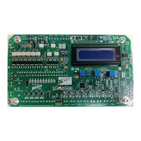
PTronik ECo Master Controller User manual

This quick start guide provides the user very basic information required to make the ECo
controller pulse solenoid valves and to make changes to the time and pressure settings. The
user is referred to the ECo manual for detailed connection and setup information and all
safety and warning instructions. The ECo should only be installed by a suitably qualified
person and all local electrical standards must be observed.
Top Board Layout
Bottom Board Layout
LCD Screen
Three utton
Interface
Input Sensors
Output Relays
Modbus RTU and/or
extension cards
Solenoid
Valve
Outputs
110/240
VAC
Input
24VDC Input
Or Output
Fuse (AC
version)
Cleanup
24VDC connections
for tube cleaning valves
DP sensor
Quick Start Guide
ECo Master Controller

Connecting Power and Solenoid Valves
If the ECo has been purchased as a complete unit then undo the 4 dome nuts and remove
the face plate. Remove the PC from the brass spacers to access the bottom of the board.
DO NOT double up solenoid valves, only connect one solenoid valve per position.
DO NOT mix commons between the main and extension cards if extension cards are connected.
Doing both these will cause the ECo to detect valve faults.
DC SOLENOID VERSION - AC input power and 24VDC
solenoid output
For this configuration the AC input voltage can be
between 100-240VAC, but the output voltage is fixed
at 24VDC
1. Connect the 100 to 240V AC incoming power
supply to terminal marked ENA (terminal J103).
This plug is removable to assist the installation
process.
2. Connect the 24VDC solenoid coils to terminal
marked SOLENOIDS (terminal J306). This plug is
removable to assist the installation process.
DC SOLENOID VERSION - DC input power and DC
solenoid output
For this configuration the DC input voltage can be
between 10-30VDC and the output voltage to the coils
is identical to the input voltage. So 10VDC in, 10VDC
out. 24VDC in, 24VDC out etc.
1. Connect the DC incoming power supply to
terminal marked DCVI (terminal J104)
2. Connect the 24VDC solenoid coils to terminal
marked SOLENOIDS (terminal J306). This plug is
removable to assist the installation process.
AC SOLENOID VERSION - AC power input and identical
AC solenoid output
For this configuration the AC input voltage can be
between 100-240VAC and the output voltage to the
coils is identical to the input voltage. So 240V in, 240V
out. 110V in, 110V out etc.
1. Connect the 100 to 240V AC incoming power
supply to terminal marked ENA (terminal J103).
This plug is removable to assist the installation
process.
2. Connect the 100 to 240V AC solenoid coils to
terminal marked SOLENOIDS (terminal J306). This
plug is removable to assist the installation process.
2
2
2

ifferential Pressure Measurement (Internal Sensor)
The ECo controller has an onboard pressure sensor used to measure the differential
pressure over the filter bags.
1. Connect the measurement tubes to the onboard
differential pressure sensor. PTronik recommend a
silicone based flexible hose that can be stretched over
the DP sensor input and output.
If the ECo has been purchased from PTronik pre-fitted inside an
enclosure, then bulkhead fittings will be provided on an external
point on the enclosure (see picture to the left).
1. For ECo-T only, the ECo-0 does not have tube cleaner
fitted. The high pressure (HP) air supply must not exceed
7 bar. This is the cleaning air used to clean the
measurements tubes.
2. The clean side measurement (C or L) must be connected
to the clean low-pressure side of the baffle plate.
3. The dirty side measurement (D or H) must be connected
to the dirty side of the baffle plate.
DO NOT connect high pressure air into the clean or
dirty side tube connections. This will damage the
differential pressure sensor and result in the board
not operating correctly.
Main Run Page
The main run page gives the user a snap shot of the current status of the dust collector.
There is a lot of information on this screen so please take a minute to read this section.
2
5
3
2
8
9
6
7
4
0
2
3

MODEL OF PTronik
CONTROLLER
Indicates the model of the PTronik controller. Visually the E10, Eco and ECo
look very similar.
2 COUNT DOWN TIME Indicates the time in seconds until the next valve pulses.
3 NEXT VALVE Indicates the next valve that will pulse. This will be a number between 1 and
240 depending on setup and how many extension cards are connected.
4 PERCENTAGE
SAVINGS
Indicates the number of pulses saved operating in differential pressure
mode when compared to a sequential timer with identical on and offtime
settings. The higher to valve the greater the savings achieved.
5 DIFFERENTIAL
PRESSURE SENSOR
Indicates what the ECo is using to control the dust collector
• DP = The ECo is using the internal differential pressure sensor
• XDP = The ECo is using an external differential pressure sensor
6 DIFFERENTIAL
PRESSURE VALUE
Indicates the current differential pressure over the filter bags. The units of
measurement can be
• mmH20 = mm of water column
• inH20 = inches of water column
• kPa = kilopascals
7 DIFFERENTIAL
PRESSURE ALARM
Indicates what alarm level the current differential pressure reading is at, this
is a user defined setting
• U Low = Ultra Low Differential Pressure
• Low = Low Differential Pressure
• High = High Differential Pressure, timer OFF time 1 active
• Fast = Higher Differential Pressure, timer OFF Time 2 active
• Alarm = Differential Pressure above selected alarm level
8 ALARM STATE Indicates the alarm status for alarms 1 to 8 (the screen will toggle between
A1IA2IA3-A4+ and A5IA6-A7-A8-).
• I = Interrupt
• - = alarm disabled
• + = alarm enabled
• * = alarm enabled and ON (activated)
9 SOLENOID STATE Indicates the last solenoid valve that fired and what the result of the valve as
(whether the coil of the last valve is faulty or not).
• OK = NO Fault
• OC = Open Circuit
• SC = Short Circuit
0
TUBE CLEANER Indicates the number of times the tube cleaning valves have fired
MANUALLY
STOPPING THE DUST
COLLECTOR
Indicates the current state of the controller. The dust collector can be
manually halted if required.
• Halt = The dust collector has been halted either manually or by the
differential pressure cleaning mode
• Pulse = The dust collector is pulsing
2
MODE OF
OPERATION
Changes the operation of the dust collector from between manual
(sequential) or auto (on demand) modes
• Auto= The dust collector is running in on demand mode, it is using
the differential pressure sensor to control the pulsing
• Man = The dust collector is running in manual mode and is
operating as a basic sequential timer

If any of the three buttons are pressed the following screen will appear. This allows the user
to change between auto or manual mode, pulsing or halting and allow the user to enter the
Menu section.
3
PULSE OR HALT Press on the left button to manually change the state between Halted and
Pulsing.
This option is only available in manual mode. If the unit is
in Auto mode it cannot be manually halted.
4
MENU Press on the middle button to check alarms, enter maintenance mode or to
alter the settings of the controller.
5
AUTO OR MANUAL Press on the right button to manually change the controller between
Manual and Auto mode.
Accessing the Settings Area
From the main screen, continue pressing the middle button unit the Enter CODE page
appears
To enter the code, select the left DOWN or right UP buttons. The
password code for all controllers is set to 4.
When this has been entered enter the middle SET button.
Timer Settings
This menu allows the user to change the settings of the controller such as number of valves,
sequencing, the pulse on and off times. Keep pressing NEXT until the TIMER Setup page is
displayed.
To modify the controller timer settings, enter the middle Select
button.
2
This page specifies the number of valves connected to the ECo.
3
4
5

To alter the number of valves connected to the system use the left
DOWN or right UP buttons. When the desired number of valves has
been entered enter the middle SET button.
3
Keep pressing the set button to skip the next few pages until the
user gets to OnTime page.
This page modifies the length of the pulse duration.
The pulse duration is user selectable in milli seconds (ms) and can be
between 1ms to 999ms in length.
To alter the on time OnTime select the left DOWN or right UP
buttons. When the desired on time has been entered enter the
middle SET button. In this example the on time is 150 milli seconds.
4
This page modifies the length of time between pulses. The interval
between pulses is user selectable in seconds (sec) and can be
between 1s to 999s in length.
OffTime - This is the off time used during normal
operation when the differential pressure is between Low
and Fast settings (see ODC section following)
OffTime2 - This is the off time used during normal
operation when the differential pressure is between Fast
and High settings (see ODC section following)
To alter the off times, select the left DOWN or right UP buttons.
When the desired off time has been selected enter the middle SET
button. In this example the off time 1 is 15 seconds and off time 2 is
7 seconds.
On emand Cleaning (O C) Settings
This menu allows the user to change the differential pressure settings that initiate and
terminate the cleaning cycle. Keep pressing NEXT until the ODC Setup page is displayed.
To modify the on demand cleaning settings, select the middle SELECT
button.
2
This page specifies the units for differential pressure measurement.
The user has three options
mmH2O – this unit of measurement is millimetres of water
gauge. The range of measurement for this unit is 0 to
250mm H2O
inH20 – this unit of measurement is inches of water gauge.
The range of measurement for this unit is 0 to 10” water
KPa – this unit of measurement is kilopascals. The range of
measurement for this unit is 0 to 2.5KPa.
To alter the units, select the left DOWN or right UP buttons. When
the desired units have been selected enter the middle SET button.

3
This page specifies the differential pressure levels to initiate and
terminate the pulsing sequence. The user needs to program four
differential pressure levels
Low = Low Differential Pressure. When the differential
pressure drops below this value the ECo will stop pulsing
the solenoid valves.
High = High Differential Pressure. When the differential
pressure is between the Low and High settings then the ECo
will use the OFF time 1 setting to pulse the solenoids valves.
Fast = Higher Differential Pressure. If the differential
pressure keeps increasing past the High setting, then the
dust collector is not pulsing frequently enough. When the
differential pressure exceeds the Fast setting then the ECo
will use the OFF time 2 setting to pulse the solenoids valves.
Alarm = Alarm level. If the differential pressure continues to
increase, then the dust load is either too high or there has
been multiple failures of the solenoid valves.
To alter the differential pressure values, select the left DOWN or
right UP buttons. When the desired units have been selected enter
the middle SET button.
Maintenance Mode
Maintenance mode allows the user to manually pulse and test the valves. Keep pressing
NEXT until the Maintenance page is displayed.
To enter maintenance mode, select the middle SELECT button
2
This page allows the user to select the valve to test.
To select the valve to pulse, select the left DOWN or right UP
buttons. When the valve to be tested has been selected hit the
middle PULSE button to test the valve
3
This page shows the test result of the valve just pulsed.
The test result of the coil will be shown to the right of the PULSED!
text and will be one of the following three possibilities
OK – The solenoid valve is functioning correctly
SC – The solenoid valve is showing a short circuit. This could
mean the
OC – The solenoid valve is showing an open circuit. This
could mean the valve is not connected or the coil has burnt
out.
Enter DONE to return to the main menu or NEXT to test and pulse
another valve

Further Assistance Required?
If a full manual or further assistance is required then please contact PTronik
Tel: +61 2 4578 9611
Website: https://www.ptronik.com/contact-us
Email: [email protected]
Table of contents
Other PTronik Controllers manuals
Popular Controllers manuals by other brands
Mitsubishi Electric
Mitsubishi Electric MELSEC Q Series Reference manual
Lamtec
Lamtec FA1 quick reference
Sundrax
Sundrax PixelGate Arma user manual

DUNIWAY Stockroom
DUNIWAY Stockroom Terranova 960 instruction manual

Emerson
Emerson Bettis RTS Installation, operation and maintenance manual
Panasonic
Panasonic CZ-64ESMC3 installation instructions
