DUNIWAY Stockroom Terranova 960 User manual

DUNIWAY STOCKROOM CORP.
1 of 30
Instruction Manual
TerranovaModel 960
Dual - Vacuum Gauge Controller
Cold Cathode - CCG-525
&
Convection - CVT-075
Copyright © 2008 by Duniway Stockroom Corp.
rev060409sr
TELEPHONE: 650-969-8811 TOLL-FREE (U.S. only): 800-446-8811 FAX: 650-965-0764 EMAIL: [email protected]
www.duniway.com

DUNIWAY STOCKROOM CORP.
2 of 30
Table of Contents
I Safety Information page 4
I Overview page 5
A. Front View, Back View and Dimensions
B. General Description
C. Specifications
D. Controls and Indicators
E. Gauge Tube (Sensor) and Cables
II Installation page 10
A. Unpack the Controller
B. Mount the Controller
C. Select the CCG
D. Select the CVT Tube
E. Mount the CCG and CVT Tubes on the Vacuum System
F. Attach the CVT Sensor Cable: Part Number CVT-275
G. Attach the CCG Sensor Cable: Part Number 05-410-SHV
H. Make Accessory Connections
I. Check Supply Voltage
J. Attach the Power Cord
III Operation page 14
A. Turn Power On
B. Fuses
C. Front Panel Controls
D. Set Pt 1 High Default Value: OFF
E. Set Pt 1 Low Default Value: OFF
F. Set Pt 2 High Default Value: OFF
G. Set Pt 2 Low Default Value: OFF
H. Autorange
I. CCG Calibrate
J. CVT ATM
K. CVT Zero
L. Units Default Values: Torr/mTorr
M. Reset of Stored (Default) Values
N. Set Point Activation/Deactivation Diagram
O. Display States and Ranges - Autorange and Manual
P. CVT Convection Gauge with Other Gases
Q: CCG Cold Cathode Gauge with Other Gases
R. Analog Output
S. Serial Interface
TELEPHONE: 650-969-8811 TOLL-FREE (U.S. only): 800-446-8811 FAX: 650-965-0764 EMAIL: [email protected]
www.duniway.com

DUNIWAY STOCKROOM CORP.
3 of 30
IV Trouble Shooting page 24
A. For the CCG
B. For the CVT/Convection Gauge
C. Error Codes
VI Application Note - Set Point Relays page 26
A. Rated Voltage vs. Current - Resistive Loads
B. Protective Circuits for Non-Resistive Loads
VI Return Procedure page 28
VIII Warranty/CE page 29-30
List of Figures
Figure 1: Model 960 Front View page 5
Figure 2: Model 960 Rear View page 5
Figure 3: Model 960 Dimensions page 5
Figure 4: CVT-275 and CCG-525 page 11
Figure 5: CVT Sensor Connector 15 Pin Female D page 11
Figure 6: 960 to CVT Cable Sensor Pin Connections page 12
Figure 7: Model 960 Accessory Connector - Pins page 13
Figure 8: Accessory Connector -- Signals & Pins page 13
Figure 9: Set Point Activation/Deactivation Diagram page 17
Figure 10: Display States and Ranges page 18
Figure 11: CVT Indicated vs. True Pressure; Other Gases page 19
Figure 12: CCG Correction Factor for Gases Other Than N2 page 20
Figure 13: Analog Output and Displayed Pressure page 21
Figure 14: Serial Output and Displayed Pressure page 22
Figure 15: Serial RS-232 Cable for PC Computer page 23
Figure 16: Model 960 Error Codes page 25
TELEPHONE: 650-969-8811 TOLL-FREE (U.S. only): 800-446-8811 FAX: 650-965-0764 EMAIL: [email protected]
www.duniway.com

DUNIWAY STOCKROOM CORP.
4 of 30
Safety Information
Explosive Gases and Solvents
WARNING!
Do not use the Model 960 Dual-Hybrid Gauge Controller to measure the pressure of combustible
gas or solvent mixtures. The Convection gauge normally operates at low temperatures, but it is
possible that momentary transients or controller malfunction may cause ignition of combustible
mixtures, which then might explode and cause damage to equipment and injury to personnel.
Limitation on use of Compression Mounts
WARNING!
Do not use a compression mount (quick-connect) for attaching the gauge tube to the vacuum sys-
tem in applications that may develop positive pressures. Positive pressures may cause the tube to
be blown out of a compression fitting and damage equipment and injure personnel.
Caution - High Voltage
The Terranova Model 960 and the 525 Cold Cathode Gauge (CCG) operate at
High Voltage. The High Voltage of -2,000 volts can be dangerous to equipment
and personnel if exposed and contacted. Connectors and cables protected and
normally safe, but care must be exercised. Always turn power OFF prior to con-
necting and disconnecting cables.
Please let us Know...
Terranova products are the most advanced instruments of their type available from any
manufacturer. We have made this Instruction Manual as complete and clear as possible.
Let us know if you have any comments that can make this manual or our products more
useful.
TELEPHONE: 650-969-8811 TOLL-FREE (U.S. only): 800-446-8811 FAX: 650-965-0764 EMAIL: [email protected]
www.duniway.com

DUNIWAY STOCKROOM CORP.
5 of 30
IOverview
A. Front View, Back View and Dimensions
Figure 1: Model 960 Front View
Figure 2: Model 960 Rear View
Figure 3: Model 960 Dimensions
TELEPHONE: 650-969-8811 TOLL-FREE (U.S. only): 800-446-8811 FAX: 650-965-0764 EMAIL: [email protected]
www.duniway.com

DUNIWAY STOCKROOM CORP.
6 of 30
B. General Description
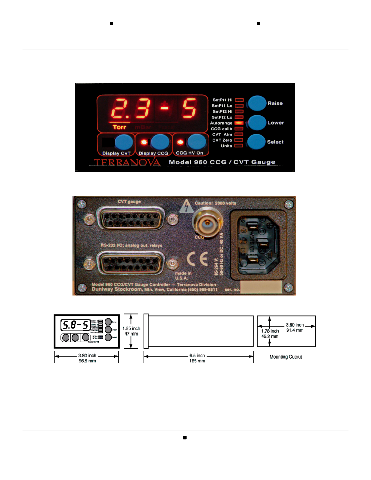
The Terranova Model 960 CVT-CCG Vacuum Controller displays vacuum pressure as measured
from both a Cold Cathode gauge (CCG) and a Convection Enhanced Pirani (CVT) gauge. The
960 is housed in a 1/8 DIN enclosure and is simple to operate.
For the CCG, the 960 supplies -2000 VDC and senses/displays the ion current, which is propor-
tional to the pressure.
For the CVT/Convection gauge, the 960 displays vacuum pressure as measured from a CVT-275
Convection Enhanced Pirani gauge tube. It displays vacuum measurements based on thermal con-
ductivity of a gas. The 960 controller covers the range from 0.1 mTorr to 995 Torr, 0.1 µBar to
995 mBar or 0.01 Pascal to 130 kPascal, user selectable.
C. Specifications
1. Useful Measuring Range
CCG:
6 decades; for Duniway CCG-525 and Varian 525 CCG tubes: 1 x 10⁻⁸ torr to 1 x 10⁻² torr
CVT:
7 decades for CVT-275: 0.1 x 10⁻³ torr to 1 x 10+3 Torr.
2. Display Range
CCG:
1.0 x 10 - 8 torr to 1.0 x 10 - 2 torr
CVT:
1.0 x 10- 4 torr to 1.0 x 10 + 3 torr; pressures lower than -19 mTorr (µBar) display LO; pressures
higher than 995 Torr (mBar) or no tube attached to cable, display HI; if cable is not connected to
the unit, display shows OFF
3. Input to the 960 Controller
CCG:
Ion current is measured in the HV supply
CVT
Pressure is calculated from the gauge output according to gauge supplier’s algorithm, confor-
mance to published data is typically within +/- 1%.
4. Units of Display
For both CCG and CVT:
Torr, mBar, Pascal, user selectable
TELEPHONE: 650-969-8811 TOLL-FREE (U.S. only): 800-446-8811 FAX: 650-965-0764 EMAIL: [email protected]
www.duniway.com

DUNIWAY STOCKROOM CORP.
7 of 30
5. Full Scale
CCG:
1.0 x 10⁻² torr
CVT
995 Torr (mBar)
6. Calibration Adjustments:
CCG:
CCG Calibrate
UNITS
CVT:
GAUGE ZERO adjust
UNITS
CONV. ATM adjust
7. Vacuum Gauge
CCG:
one Duniway CCG-525 or Varian 525 Cold Cathode gauge
CVT
one CVT-275 or G-P 275 CONVECTRON®.
8. Operating Temperature Range
+2 to +50 deg. Celsius
9. Process Control Set Points
two, with independent High and Low set points for each relay, for flexible control of hysteresis,
assignable to either sensor
10. Process Control Relays
two relays; contacts rated at 2 amp/240 VAC, 300 VDC
11. Nonvolatile Memory for all user specified parameters
12. Analog Output
logarithmic, 0.5 volts/decade; 0.1 mtorr = 4.00 volts
13. Output Voltage
CCG
-2 kv
TELEPHONE: 650-969-8811 TOLL-FREE (U.S. only): 800-446-8811 FAX: 650-965-0764 EMAIL: [email protected]
www.duniway.com

DUNIWAY STOCKROOM CORP.
8 of 30
14. Mounting
The 960 may be used as a bench-top instrument or it may be mounted in an instrument panel.
Clips are provided for panel mounting.
15. RS-232 Input/Output
allows user to read pressure, set points and other parameters; 9600 baud, 8-N-1; available through
the accessory connector
16. Operating Voltage
The Model 960 has a universal power supply, which operates on input voltages from 90 VAC to
240 VAC 47 to 65 Hz; input is through a power input receptacle on the rear panel.
17. Fuses
Input power is protected by internal, self-resetting, fuses in both lines of the input power. When
the input current exceeds 2 amps for 25 seconds, the fuses open. After 30 seconds open, the fuses
re-set to closed.
18. Weight, Model 960 only; does not include cable or CVT and CCG tubes
0.9 lb. /0.4 kg
D. Controls and Indicators
1. DISPLAY CVT button
allows the user to select CVT (Convection) to be shown on the digital display
2. DISPLAY CCG button
allows the user to select CCG (Cold Cathode Gauge) to be shown on the digital display
3. CCG HV On button allows the user to turn high voltage on/off to the CCG when the
960 is not in the Autorange mode.
4. SELECT button
Allows selection of parameters to be adjusted, e.g. Set Points
5. RAISE and LOWER buttons
used for adjustment of gauge and instrument parameters
6. Digital Display
2-digit pressure, sign (+/-) and 1-digit exponent, 7-segment bright red LED, 10 mm high
7. Display Indicators
bright red individual LED for miscellaneous indicators
TELEPHONE: 650-969-8811 TOLL-FREE (U.S. only): 800-446-8811 FAX: 650-965-0764 EMAIL: [email protected]
www.duniway.com

DUNIWAY STOCKROOM CORP.
9 of 30
E. Gauge Tube (Sensor) and Cables
Part Number Description
CVT-275-101 Sensor, Convection, 1/8 NPT port
CBL-275 Cable, Convection Sensor, 10 ft.
CCG-525-KF25 Sensor, Cold Cathode, KF25 flange
CCG-525-KF40 Sensor, Cold Cathode, KF40 flange
CCG-525-CFF Sensor, Cold Cathode, 2.75” CFF
CCG-525-1 Sensor, Cold Cathode, 1.0” Tube
05-410-SHV Cable, Cold Cathode Sensor, 10 ft, Bakeable/Radiation Res..
05-110-SHV Cable, Cold Cathode Sensor, 10 ft. RG-59
CCGs and CVTs may be ordered from:
Duniway Stockroom Corp.
48501 Milmont Drive
Fremont,CA 94538
Telephone: (800) 446-8811 or(650) 969-8811
Facsimile: (650) 965-0764
Internet: www.duniway.com
For other Sensor flanges or Cable lengths, please inquire.
TELEPHONE: 650-969-8811 TOLL-FREE (U.S. only): 800-446-8811 FAX: 650-965-0764 EMAIL: [email protected]
www.duniway.com

DUNIWAY STOCKROOM CORP.
10 of 30
II Installation
A. Unpack the Controller
Carefully unpack the Model 960 Dual - Hybrid Vacuum Gauge Controller. The shipment includes
these components:
• controller unit
• power cord
• mounting clips
• D-sub 15 accessory connector
• this instruction manual
If your controller does not have all of these items, call Duniway Stockroom. If anything appears
to have been damaged in shipment, contact the shipper.
B. Mount the Controller
You can rest the controller unit on a bench, table top, or shelf, or you can mount it in a rack or
cabinet. The controller unit is housed in a standard 1/8 DIN box. If you are mounting the unit in
a panel, the cutout dimensions are 1.78 inch by 3.60 inch (45.2 mm by 91.4 mm), see fig. 3, page
9. One mounting clip attaches to each of the sides of the controller unit. To attach the clip, slide
the beveled surfaces of the clip under the cutout on the side of the box and push the clip toward
the back of the unit.
Be sure to leave enough clearance at the back of the controller unit for easy access to cable con-
nections and enough space around the vents of the unit to allow heated air to escape.
C. Select the CCG
The Model 960 controller is designed to work with the Duniway CCG-525 and Varian Model 525
Cold Cathode gauges.
D. Select the CVT Tube
The Model 960 controller is designed to work with the CVT-275 or the
Brooks/Helix/Granville-Phillips type 275 Convectron®sensor tubes, both of which are supplied
by Duniway Stockroom Corp.
TELEPHONE: 650-969-8811 TOLL-FREE (U.S. only): 800-446-8811 FAX: 650-965-0764 EMAIL: [email protected]
www.duniway.com

DUNIWAY STOCKROOM CORP.
11 of 30
Figure 4: CVT-275 and CCG-525
E. Mount the CCG and CVT Tubes on the Vacuum System
Make sure that the sensor tubes are securely connected to the vacuum system, using good vacuum
practice.
F. Attach the CVT Sensor Cable: Part Number CVT-275
NOTE: Be sure that the Terranova 960 power is OFF before connecting/disconnecting sensors.
The sensor cable has a 9-pin D-sub connector on one end, which plugs into the 960, see Figure 5,
below. Connect the 9-pin D-sub plug of the gauge cable to the 9-pin connector on the back of the
960 controller unit. Push the plug onto the connector until it is firmly in place. Tighten the retain-
ing screws to make certain the connector remains in place. Loose connections can cause faulty
readings.
Figure 5: Model 960 CVT Sensor Connector -- 15 Pin Female D-Sub Connector
TELEPHONE: 650-969-8811 TOLL-FREE (U.S. only): 800-446-8811 FAX: 650-965-0764 EMAIL: [email protected]
www.duniway.com

DUNIWAY STOCKROOM CORP.
12 of 30
275
Terranova 960 CVT
D-15 pins gauge connector pin
8 1
7 1
6 5
5 2
4 3
3 3
2 shield
no connection 4
Figure 6: Figure Terranova 960 15-D Connector to 275 Connector
Current available for +15 volts from pins 4 and 5, and for -15 volts from pins 6 and 7 is internally
protected and limited to approximately 0.75 amp total for each supply. If excessive current is tak-
en through any of the power output pins, the internal protection will shut off the power for the
affected voltage. It will be necessary to disconnect power for the 960 for a few minutes to allow
the internal protection device to cool down and reset itself.
G. Attach the CCG Sensor Cable: Part Number: 05-410-SHV
NOTE: Be sure that the Terranova 960 power is OFF before connecting/disconnecting sensor ca-
bles.
The CCG Sensor Cable is a coaxial high voltage cable, with a type 05 BNC coaxial connector on
the 525 sensor end a type SHV coaxial connector on the 960 end. The operating voltage of the
525 sensor is -2,000 volts
TELEPHONE: 650-969-8811 TOLL-FREE (U.S. only): 800-446-8811 FAX: 650-965-0764 EMAIL: [email protected]
www.duniway.com

DUNIWAY STOCKROOM CORP.
13 of 30
H. Make Accessory Connections
The 15-pin D-sub Accessory Connector is on the rear panel of the 960, see Figure 8, below. The
connector has female pins; the mating connector must have male pins. Mating D-sub 15 connec-
tors are available from many of the normal electronic sources. If you need help identifying a
source, please contact us.
Figure 7: Model 960 Accessory Connector -- 15 Pin Female D-Sub Connector
Following are pin assignments for the Accessory Connector:
15-pin Accessory Connector
pin 1 set point #1 relay, normally closed
pin 2 set point #1 relay, common
pin 3 set point #1 relay, normally open
pin 4 set point #2 relay, normally closed
pin 5 set point #2 relay, common
pin 6 set point #2 relay, normally open
pin 7 Tx, RS-232 signal out of the 960; 9600-N-8-1
pin 8 Rx, RS-232 signal into the 960
pin 9 ground, RS-232 and analog common
pin 10 reserved
pin 11 reserved
pin 12 reserved
pin 13 log analog output, 1Kohm output, 0.5 volts/decade
pin 14 reserved
pin 15 reserved
Figure 8: 960 -- Accessory Connector Signals and Pins
NOTE: See also Section VI - Application Note - Protective Circuits for Set Point Relays
I. Check Supply Voltage
The Model 960 incorporates a universal power supply. This allows the 960 to operate on any input
voltage from 90 VAC to 240 VAC, 47 to 65 Hz.
J. Attach the Power Cord
Plug the power cord into the receptacle in the power module on the rear of the 960.
TELEPHONE: 650-969-8811 TOLL-FREE (U.S. only): 800-446-8811 FAX: 650-965-0764 EMAIL: [email protected]
www.duniway.com

DUNIWAY STOCKROOM CORP.
14 of 30
III Operation
A. Turn Power On
Plug the AC power end of the power cord into an electrical outlet. The loudspeaker will “beep”
and test all indicators while the controller executes its self test. After being turned on, the instru-
ment will go through the following sequence:
• “beeper”
• indicators for TORR, MTORR, MBAR, ΜBAR, KPASCAL, PASCAL
• 9 LED indicators for set points and other functions
• all four digits will light, including decimal points
• display shows the model number of the instrument, 960
• display shows software version, e.g. 1.10
The 960 will go into normal operation and begin measuring pressure. If the CCG or CVT is not
connected, the display will show OFF when that gauge/sensor is selected from the front panel
GAUGE SELECT button. If the system pressure is greater than 100 mTorr for the CCG or 999
Torr for the CVT the display will show HI.
B. Fuses
Input power is protected by internal, self-resetting fuses in both lines of the input power. When
the input current exceeds 2 amps for 25 seconds, the fuses open. After 30 seconds open, the fuses
re-set to closed.
C. Front Panel Controls
The Model 960 allows flexible configuration of operation using simple entry from the front
panel buttons labeled DISPLAY CVT, DISPLAY CCG, CCG HV ON, SELECT, RAISE and LOW-
ER. Parameters which you may adjust are selected by scrolling through a list (using the SELECT
button) which begins with SET PT 1 HIGH. Each time the SELECT button is pushed, the LED indi-
cator advances to the next parameter. The LED indicators will be lit to indicate which parameter
is being adjusted and the digital display will flash to indicate the value of the parameter being ad-
justed.
Each push of a button will give a short “beep” from the loudspeaker to confirm the button was
pushed. If you have reached the limit of adjustment or if the button push is not allowed, the loud-
speaker will give a long “beep” and error display E02.
Following is a detailed description of parameter selection and adjustment:
D. Set Pt 1 High Default Value: OFF
This sets the high limit of the set point. Above this pressure, the set point relay will be de-ener-
gized. Press the RAISE or LOWER buttons to enter the value desired. The minimum value is OFF;
this shuts the set point off.
For the CCG, the next increment is 0.1 in the Least Significant Digit in the range 1.0 x 10⁻⁷ torr
to 1.0 x 10⁻³ torr.
TELEPHONE: 650-969-8811 TOLL-FREE (U.S. only): 800-446-8811 FAX: 650-965-0764 EMAIL: [email protected]
www.duniway.com

DUNIWAY STOCKROOM CORP.
15 of 30
For the CVT, the next increment is 0.1 in the Least Significant Digit in the range 3.0 x 10⁻³ torr
to 5.0 x 10+2 torr.
When the RAISE or LOWER buttons are pressed, the display will change slowly at first. If you hold
the button down for a few seconds, the rate of change will increase to allow you to make large
changes more quickly.
SET PT 1 HIGH operates in conjunction with SET PT 1 LOW. While the 960 is in this mode, the set
point may be assigned to either CCG or CVT/275 by pressing either GAUGE DISPLAY button.
E. Set Pt 1 Low Default Value: OFF
This sets the low limit of the set point. This is the pressure at which the set point relay will be
energized. Operation is similar to that of SET PT1 HIGH above. The minimum value is OFF; this
shuts the set point off.
SET PT 1 LOW operates in conjunction with SET PT 1 HIGH.
NOTE: The High and Low set points allow the user to set the hysteresis of the set point
operation. As the system is pumped down, the set point relay will be energized (set point
turns on) as the pressure drops below SET PT 1 LOW. The relay will remain energized until
the pressure rises above SET PT 1 HIGH.
It is not possible to adjust the High set point to be lower than the Low set point. If you adjust the
High set point below the pressure previously selected for the Low set point, the 960 will automat-
ically reduce the value for the Low set point so that it is two increments lower than that of the
High set point.
F. Set Pt 2 High Default Value: OFF
This operates in the same manner as SET PT 1 HIGH, described above.
G. Set Pt 2 Low Default Value: OFF
This operates in the same manner as SET PT 1 LOW, described above.
Set Point Operation
When pressure values have been entered for a set point (1 or 2) and assigned to a gauge (CVT or
CCG), the set point relay operates as follows: As the pressure on the assigned gauge falls through
the chosen “Set Point N Low” pressure, the relay actuates, either opening (if the Normally Closed
pin has been used on the Auxiliary I/O connector) or closing (if the Normally Open pin has been
used on the Auxiliary I/O connector). Likewise, as the pressure on the assigned gauge rises
through the chosen “Set Point N High” pressure, the relay de-actuates, either closing (if the Nor-
mally Closed pin has been used on the Auxiliary I/O connector) or opening (if the Normally Open
pin has been used on the Auxiliary I/O connector).
NOTE: See also Section VI - Application Note - Protective Circuits for Set Point Relays
NOTE: See also Section IV-N - Set Point Activation/Deactivation Diagram
TELEPHONE: 650-969-8811 TOLL-FREE (U.S. only): 800-446-8811 FAX: 650-965-0764 EMAIL: [email protected]
www.duniway.com

DUNIWAY STOCKROOM CORP.
16 of 30
H. Autorange Default Value: Off
When AUTORANGE is selected during set up, the 960 automatically switches at appropriate
pressure points, from CVT to CCG as pressure falls and from CCG to CVT as the pressure rises.
As the pressure falls, the transition from CVT to CCG occurs at 3 x 10⁻³ torr, at which point, the
CCG HV is turned ON, and the display changes from showing CVT pressure to showing CCG
pressure.
As the pressure rises, the transition from CCG to CVT occurs at 6 x 10⁻³ torr, at which point, the
display changes from showing CCG pressure to showing CVT pressure. CCG HV is turned OFF
as the pressure continues to rise above 1 x 10⁻² torr. (This delay is set up to provide better opera-
tion during transient pressure spikes).
.
I. CCG Calibrate Default Value: 1.00 (Internal value)
This allows the user to modify the reading for the CCG gauge by multiplying by a value between
0.5 and 2.0. This is convenient for calibration of the CCG. The multiplier is internal, and is not
seen by the user. The digital display shows the result of the CCG pressure reading multiplied by
the internal multiplier.
J. CVT ATM
Convection ATM No Default Value - Display Shows CVT Output
Use the RAISE and LOWER buttons to set the displayed pressure to the desired pressure
reading. Initially, the display may read a value which is substantially higher than atmo-
spheric pressure, or it might even indicate “HI”. Just proceed to use the LOWER button
to bring the reading into the range. If you try to set CVT ATMOS when the pressure is
less than approximately 2.0+2 Torr (3.5+2 mBar) you will get a long ‘beep’ from the
unit’s annunciator.
You can use this function to set the atmospheric pressure reading for CVT 275 convection gauges
You should know the local barometric pressure before proceeding; your local airport or internet
weather web-site (www.weather.com) may have this information. Normal barometric pressure is
approximately 7.6+2 Torr (1.0+3 mBar) at sea level.
TELEPHONE: 650-969-8811 TOLL-FREE (U.S. only): 800-446-8811 FAX: 650-965-0764 EMAIL: [email protected]
www.duniway.com

DUNIWAY STOCKROOM CORP.
17 of 30
K. CVT Zero
This allows the user to adjust the zero for the CVT. Before making this adjustment, the CVT
should be connected to a vacuum system at a pressure lower than 0.1-3 torr. This adjustment may
also be used to set the display to a specific value if you know the pressure through other means.
For example, if the CVT to be adjusted is attached to a system that has another gauge which has
been independently calibrated, the CVT may be made to read the same as the calibrated
gauge.The ZERO function may be adjusted only when the CVT pressure is below 5.0-3 torr (6.5-
3 Bar). If you try to set the ZERO when the pressure is above 5.0-3 torr, you will get a long ‘beep’
from the unit’s annunciator.
L. Units Default Value: Torr/mTorr
On the next press of the SELECT button, you will be in the UNITS mode. This allows selection
of the units to be used in display of the pressure for both gauges.
The display will flash with the currently selected UNITS.
Press either the RAISE or LOWER buttons to sequence through the choices: Torr, mBar, Pascal.
The UNITS of measure apply to both gauges; it is not possible to select Torr for one gauge and
mBar for the other gauge.
M. Reset of Stored (Default) Values
This allows you to recover the factory (default) settings for all stored values and resets the SET
POINTS to off. For a system that is far out of calibration, the factory settings provide a good start-
ing point for re-calibrating or adjusting the gauge controller. To recover the factory settings, un-
plug the 960 from its power source. Press and hold RAISE and LOWER buttons at the same time;
while holding the RAISE and LOWER buttons depressed, plug the power cord in. You will hear a
few short ‘chirps’ from the loudspeaker confirming the factory settings have been entered. The
digital display will show RST to confirm the reset has been entered.
N. Set Point Activation/Deactivation Diagram
Figure 9: Set Point Activation/Deactivation Diagram
TELEPHONE: 650-969-8811 TOLL-FREE (U.S. only): 800-446-8811 FAX: 650-965-0764 EMAIL: [email protected]
www.duniway.com

DUNIWAY STOCKROOM CORP.
18 of 30
O. Summary of 960 Display States and Ranges: Manual and Autorange Settings
Figure 10: 960 Display States and Range
NOTES:
TELEPHONE: 650-969-8811 TOLL-FREE (U.S. only): 800-446-8811 FAX: 650-965-0764 EMAIL: [email protected]
www.duniway.com

DUNIWAY STOCKROOM CORP.
19 of 30
P. CVT/ Convection Gauge with Other Gases
If you need to measure the pressure of gases other than air/nitrogen, refer to the following table:
True Indicated Pressure on Model 960 Display, Torr
Pressure
Torr Argon* CO2 Deuterium Freon 12 Freon 22 Helium Krypton Methane Neon Oxygen
0 0000000000
0.0001 0.0001 0.0001 0.0001 0.0001 0.0001 0.0000 0.0000 0.0002 0.0001 0.0001
0.0002 0.0001 0.0002 0.0002 0.0003 0.0002 0.0002 0.0002 0.0003 0.0001 0.0002
0.0005 0.0003 0.0006 0.0006 0.0008 0.0007 0.0004 0.0003 0.0008 0.0003 0.0005
0.001 0.0007 0.0011 0.0019 0.0015 0.0014 0.0008 0.0005 0.0018 0.0007 0.0010
0.002 0.0013 0.0023 0.0024 0.0030 0.0029 0.0016 0.0010 0.0032 0.0014 0.0020
0.005 0.0033 0.0055 0.0060 0.0075 0.0068 0.0040 0.0023 0.0077 0.0035 0.0049
0.01 0.0065 0.0109 0.0120 0.0147 0.0135 0.0080 0.0046 0.0152 0.0070 0.0097
0.02 0.014 0.022 0.024 0.030 0.027 0.016 0.009 0.031 0.014 0.020
0.05 0.033 0.055 0.060 0.073 0.069 0.041 0.024 0.077 0.035 0.049
0.1 0.064 0.107 0.120 0.142 0.136 0.082 0.046 0.158 0.070 0.097
0.2 0.126 0.208 0.247 0.270 0.259 0.163 0.085 0.310 0.140 0.192
0.5 0.307 0.494 0.673 0.599 0.582 0.427 0.214 0.764 0.353 0.477
1 0.59 0.93 1.51 1.03 1.01 0.92 0.39 1.56 0.73 0.95
2 1.12 1.67 4.02 1.59 1.62 2.16 0.68 3.23 1.60 1.90
5 2.36 3.24 261 2.38 2.54 13.2 1.25 13.3 5.10 4.85
10 3.86 4.84 2.86 3.29 1.74 28.6 21.5 10.1
20 5.67 6.39 3.21 3.61 2.23 359 584 22.4
50 7.72 8.00 3.68 4.02 2.50 845 85.7
100 8.71 9.02 4.56 4.78 2.66 226
200 9.65 12.0 5.81 6.23 3.07 303
300 11.1 16.8 6.69 7.31 3.49 383
500 15.9 29.4 8.06 8.98 4.10 603
700 21.9 48.8 9.20 10.4 4.60 861
760 23.9 56.0 9.52 10.8 4.63 943
900 29.2 88.2 10.2 11.7
1000 33.8 129 10.8 12.4
Figure 11: CVT Indicated vs. True Pressure for Gases Other Than Nitrogen
For example, if you are measuring the pressure in a system that is backfilled with carbon dioxide
(CO2), and the Model 960 display shows an indicated pressure of 56 Torr, the true pressure is 760
Torr. If the indicated pressure is 22 mTorr (0.022 Torr), the true pressure is 20 mTorr (0.02 Torr).
These data were compiled from a variety of sources and are believed to be reliable, however Du-
niway Stockroom Corp. takes no responsibility for errors in the data. If your application is critical,
we suggest you use the services of an independent laboratory to calibrate the CVT-275 gauge and
Model 960 controller to your specific application.
TELEPHONE: 650-969-8811 TOLL-FREE (U.S. only): 800-446-8811 FAX: 650-965-0764 EMAIL: [email protected]
www.duniway.com

DUNIWAY STOCKROOM CORP.
20 of 30
Q. CCG-Cold Cathode Ionization Gauge with Other Gases
If you need to measure the pressure of gases other than air/nitrogen, refer to the following table:
Multiply the indicated pressure by the gas-species correction factor in the table to obtain the true
pressure.
Note: In a gauge calibrated for nitrogen,
where the dominant gas is other than nitrogen,
divide the gauge reading by the appropriate gas ionization factor
Figure 12: CCG Correction Factor for Gases Other Than Nitrogen
For example, if you are measuring the pressure in a system that is backfilled with carbon dioxide
(CO2), and the Model 960 display shows an indicated pressure of 1 x 10⁻⁵ Torr, the true pressure
is 7 x 10⁻⁶ Torr. (0.7 x 1 x 10-5)
These data were compiled from a variety of sources and are believed to be reliable, however Du-
niway Stockroom Corp. takes no responsibility for errors in the data. If your application is critical,
we suggest you use the services of an independent laboratory to calibrate the CVT-275 gauge and
Model 960 controller to your specific application.
TELEPHONE: 650-969-8811 TOLL-FREE (U.S. only): 800-446-8811 FAX: 650-965-0764 EMAIL: [email protected]
www.duniway.com
Table of contents
Other DUNIWAY Stockroom Controllers manuals