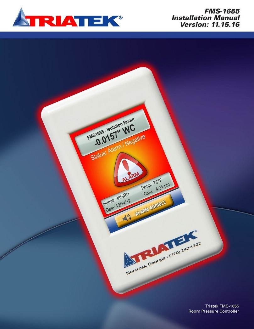
TRIATEK HMS-1655 User manual

HMS-1655
Installation Manual
Version: 03.15.17
Triatek HMS-1655
Fume Hood Controller

Due to continuous improvement, Triatek reserves the right to change product specifications without notice.
CONTROLLER SETTINGS
HMS-1655 Fume Hood Controller Settings
HMS-1655
- 2 -
Fume Hood Name / Number
Unit Model Number and Serial Number (ESN)
Sidewall Sensor Input
Normal Operating Face Velocity
Sensor Linearization (enabled or disabled)
Sensor Input Mode (normal or inverted)
Sensor Input Range (zero-based or offset)
Occupied Mode Setpoint
Unoccupied Mode Setpoint
Decommissioned Mode Setpoint
Face Velocity Deadband
Analog Output
Operating Mode (Direct or PID)
Analog Output Range (zero-based or offset)
Analog Output Upper Limit (0 – 100%)
Analog Output Lower Limit (0 – 100%)
Analog Output Input Channel (AI-1 thru AI-4, TI-1 or TI-2)
Analog Output Action (Direct or Reverse)
Analog Output Range (zero-based or offset)
Sash Switch
Operating Mode (normally-open or normally-closed)
Delay Setting (0 - 240 secs)
Relay Output
Trigger Mode (Setpoints or Operating Mode)
Input Channel (AI-1 thru AI-4, TI-1 or TI-2)
Occupied Mode High Setpoint
Occupied Mode Low Setpoint
Triatek reserves the right to change product specifications without notice. Triatek reserves the right to change product specifications without notice.

Due to continuous improvement, Triatek reserves the right to change product specifications without notice.
CONTROLLER SETTINGS
HMS-1655 Fume Hood Controller Settings
HMS-1655
- 3-
Unoccupied Mode High Setpoint
Unoccupied Mode Low Setpoint
Relay Acting Mode (Direct or Reverse)
Delay Setting (0 - 180 secs)
PID Constants
Proportional Constant (0.5 – 100.0 %)
Integral Constant (0.0 – 100.0 %)
Derivative Constant (0.0 – 100.0 %)
Alarm Limits
Occupied Mode High Alarm Setpoint
Occupied Mode High Warning Setpoint
Occupied Mode Low Warning Setpoint
Occupied Mode Low Alarm Setpoint
Unoccupied Mode High Alarm Setpoint
Unoccupied Mode High Warning Setpoint
Unoccupied Mode Low Warning Setpoint
Unoccupied Mode Low Alarm Setpoint
Audible Alert
Enabled Input Channels (AI-1 thru AI-4, TI-1, TI-2)
Operating Mode (audible or silent)
Delay Time Base (secs or mins)
Delay Setting (0 – 60)
Alarm Quiet Period Starting Hour (0 – 23)
Alarm Quiet Period Ending Hour (0 – 23)
Engineering Units
Feet per Minute or Meters per Second
Triatek reserves the right to change product specifications without notice. Triatek reserves the right to change product specifications without notice.

Due to continuous improvement, Triatek reserves the right to change product specifications without notice. Due to continuous improvement, Triatek reserves the right to change product specifications without notice.
HMS-1655
- 4 -
FAST ACTING
ELECTRONIC ACTUATOR
Controller Actuator
120/24VAC, 30Va Transformer
Supplied by Triatek
120/24VAC, 20Va Third Party
Transformer
CORRECT
CORRECT
Triatek reserves the right to change product specifications without notice. Triatek reserves the right to change product specifications without notice.
Warning
Failure to follow the wiring diagrams could result in damage to your equipment and could
void your warranty. Wiring diagrams can also be found at www.triatek.com.
Under no circumstances should a single transformer be split between actuator and controller. Doing so
will damage the actuator, the transformer, the controller or all units. A single 120/24V 30Va transformer is
required for the controller and a separate 120/24V 20Va transformer is required for the actuator.

Due to continuous improvement, Triatek reserves the right to change product specifications without notice.
SUBHEAD
Table of Contents
HMS-1655
Due to continuous improvement, Triatek reserves the right to change product specifications without notice.
- 5-
TABLE OF CONTENTS
Triatek reserves the right to change product specifications without notice. Triatek reserves the right to change product specifications without notice.
SPECIFICATIONS
……………………………………………………………………………………………………………………………6-7
GENERAL
Overview………………..……………………………………..............……………………………………………………………………8-9
Installation
…………………………………………………………….................……………………………………………………………………10
MOUNTING/WIRING
Case Dimensions………………………………………………............…………………………………………………………………………11
Display Mounting Hole Pattern…………………..........……….....…………………………………………………………………………………12
Controller Mounting Hole Pattern……………………………………….............…………………………………………………………………13
Sensor Mounting Hold Pattern/Placement………………………...........………………………………………………………………………14
Standard Sidewall Sensor (9-pin)…………………………........……………………………………………………………………………15
Analog Output to Pneumatic Actuator……………………………...….........…………………………………………………………………16
Analog Output to Electric Actuator………………….......…………......………………………………………………………………………17
Analog Input Single Flow Sensor……………………………….........…………………………………………………………………………18
Analog Input Dual Flow Sensors……………………….......……………………....……………………………………………………………19
Analog Input Sash Position Sensor………………………........…………….....………………………………………………………………20
Digital Input Occupancy Sensor………………………………….........……………………………………………………………………21
Power…………………………………………………………........……………………………………………………………………………22
Isolated Power Supply………………………………………...............……………………………………………………………………………23
COMMUNICATIONS
BACnet® MS/TP………………………………………………..........……………………………………………………………………………24
Metasys® N2 Open………………………………………………….............……………………………………………………………………25
BASIC PROGRAMMING
Introduction…………………………………………………………………………………………………………………………………26
Main Display Screen…………………………………………………………...……….....……........…………………………………………26
Configuring Fume Hood Monitor………………………........………………..........………………………………………………………………26
Calibrating Face Velocity Sensor………………………........………………..........………………………………………………………………27
Configuring Sash Position Sensor………………………........………………..........……………………………………………………………27
Calibrating Sash Position Sensor……………….......………………..........………………………………………………………………27
Configuring Sash Settings……………………......…........………………..........………………………………………………………………27
Selecting Sash Control Mode………………………........………………..........………………………………………………………………28
Calibrating the Sash Control Feature………………………........………………..........………………………………………………………28
Configuring Face Velocity Setpoints………………………........………………..........…………………………………………………………28
Configuring Face Velocity Alarm Setpoints………………………........………………..........…………………………………………………28
Changing Fume Hood Operating Mode………………………........………………..........……………………………………………………29
Configuring Analog Output for Exhaust Damper Control…………………….......………………………………………………………………29
Changing Network Settings………………………........………………..........………………………………………………………………29
Adding Password Security………………………........………………..........………………..........………………………………………………29
Changing Display Settings………………………................………………..........………………………………………………………………30
Built-in Diagnostics………………….............……........………………..........………………………………………………………………30
.
MODULE SETTINGS……………………………………………………………..............…………………………………………………………31-37
.
CLEANING THE HMS-1655 DISPLAY…………………………………….................……………………………………………………………38
COMPREHENSIVE WIRING DIAGRAM……………………………….................…....………………………………………………………39
FLOW DIAGRAMS
Unit Setup Tree…………………................................................………........……………………………………………………………………40
System Setup Tree………………………….....…..........................…..........……………………………………………………………………42
Display Setup Tree……………………………............................................……………………………………………………………………45
Diagnostics Menu Tree…………….............……………........................…………………………………………………………………………46

Due to continuous improvement, Triatek reserves the right to change product specifications without notice.
- 6 -
HMS-1655
Due to continuous improvement, Triatek reserves the right to change product specifications without notice.
Electrical
4 Analog Inputs………………………...…………………………………………………………………………………… 4-20mAdc, 0-5Vdc or 0-10Vdc
4 Analog Outputs…………………….....………………………………………………………………………………… 4-20mAdc, 0-5Vdc or 0-10Vdc
2 Thermistor Inputs…………………………………………………………………………………………………… NTC Type 2 or 3, 10kΩ @ 25˚C
4 Digital Inputs………………………………………………………………………………………… 0-5Vdc or 0-24Vdc, Active-High or Active Low
4 Relay Outputs ………………………………………………………………………………………………………………………………… 1A@24VDC
Control Signal Wire Size……………………………………………………………………………………………………………… 18-22 AWG minimum
Power Supply…………………Class 2, 24Vac ±10%, 30VA universal 120/240 to 24 Vac, 60/50 Hz, step-down isolation transformer provided
Communications
BACnet® MS/TP network…………………………………………………………………...………………… Two-wire Twisted Pair, RS-485 signaling
Metasys® N2 network………………………………………………………………………………………… Two-wire Twisted Pair, RS-485 signaling
Recommended Cable Type ………………………………………………………………………………………………………………… Belden 3107A
Touchscreen User Interface
LCD Size………………………………………………………………………………………...……………………………………………… 3.2” diagonal
LCD Type…………………………………………………………………………………….....……………………………………………… Transmissive
Resolution……………………………………………………………………………….....……………………………………………… 240 x 320 portrait
Viewing Area…………………………………………………………………………....…………………………………………… 50.60 mm x 66.80 mm
Color Depth……………………………………………………………………….....………………………………………………… 18-bit or 262K colors
Backlight Color…………………………………..………………………………………………………………………….....…………………………White
Luminous Intensity……………………....…………………………………………………………………………………..………………min 2500 cd/m2
GENERAL
Specications
Triatek reserves the right to change product specifications without notice. Triatek reserves the right to change product specifications without notice.

Due to continuous improvement, Triatek reserves the right to change product specifications without notice.
Mechanical
HMS-1655 Display Housing………………………………………………………………………………………………………… 3”W x 5”H x .1.13”D
HMS-1655 Controller Housing…………………………...………………………………………………………………………… 4.6”W x 6.6”H x 1.9”D
Environmental
Operating Temperature…………………………………………………………………………………………………………32° to 125° F Operating
Operating Humidity……………………………………………………………………………………………………10% - 95% RH, Non-condensing
HMS Air Flow Sensor
Type of Sensor ……………………………………………………………...…………………………………………………Thru-the-hood ultra sensitive
Face Velocity Accuracy…………………………………………………......…………………………………………………………0-200 FPM ± 2 FPM*
Dimensions……………………………………………………………………………………………......................……………… 2.5”H x 4.0”W x 2.0”D
NIST Traceable / Individual certification available as option
*@72°F ± 5°F
Venturi Valve (Order Separately)
Diameter……………………………………………………………………………………………………........………...………………8”, 10”, 12”, 14”O.D.
CFMRange………………………………………………………………………………………………………………………………………………35-2100
Materials …………………………………………………………………………………………………… Aluminum, Stainless Steel, Heresite Coating
Insulation…………………………………………………………………………………………………………………………………………Optional
Actuation………………………………………………...……………………………………………………………………………Electronic or Pneumatic
Part Number Guide
Due to continuous improvement, Triatek reserves the right to change product specifications without notice.Triatek reserves the right to change product specifications without notice.
- 7-
HMS-1655
Triatek reserves the right to change product specifications without notice.
GENERAL
Specications
*Accuracy is ± 5FPM when velocity drops below 60FPM or exceeds 140 FPM
HMS1655 -1-1
Sensor Type Sash Sensor
1 = single smart sidewall sensor blank = sash sensor not included
2 = dual smart sidewall sensor S = sash position sensor included

Due to continuous improvement, Triatek reserves the right to change product specifications without notice.
Triatek’s HMS-1655 Fume Hood Controller is an ultra-sensitive
instrument used to monitor and/or control the fume hood face velocit,
and is capable of measuring and displaying face velocities from zero to
200 ft/min (1.016 m/sec) with an accuracy of ±2 ft/min.
Key features of the HMS-1655 include:
• Three selectable control modes available: sidewall only, sash position
only, sash with sidewall for closed-loop performance
• Comprehensive closed-loop sash control with sidewall velocity sensing
• Full-color touchscreen display with programmable display options and
adjustable backlight
• Intuitive user interface simplifies setup and configuration of unit
• Safety Halo™ provides full 180ovisibility from anywhere in laboratory
• Audible and visual alarms
• Auxiliary universal analog inputs for use with optional sensors
• Four independent proportional-integral-derivative (PID) control loops
for controlling damper actuators, speed drives, hot water valves,
humidifiers, etc.
• Digital input used to monitor an optional fume hood sash switch, zone
presence sensor or emergency override switch.
• Relay outputs used for transmitting alarm condition to remote location
• Dedicated thermistor inputs for temperature monitoring and/or control
applications
• Multi-level password protection of touchscreen user interface
• Field calibration of both sidewall velocity sensor and optional sash
position sensor
• Multi-protocol native (BACnet®, Metasys® N2) for easy integration
with any building management system (BMS)
• Manual override of analog and relay outputs assist with test and
balance procedures
• Comprehensive real time view diagnostics tool displays built into each
unit
• Easy-to-install backplane/backplate assembly facilitates permanent
termination of all wiring
The HMS-1655 has bold, modern graphics and integrates Triatek’s
signature Safety Halo™ status indicator. This feature significantly
enhances the alarm status indication of the HMS-1655 by providing full
180° visibility of the color-coded hood statuses.
Not only can you see the status while standing directly in front of the
fume hood, you can now have full visibility from virtually anywhere in
the laboratory. The HMS-1655’s Safety Halo™ is shipped from the
factory enabled at full brightness, but may be dimmed or even disabled
completely.
The HMS-1655 is equipped with a 3.2” diagonal full-color touchscreen
display in portrait orientation (240 x 320). The password-protected menu
tree is very intuitive and simplifies the setup and configuration of the unit.
The menus incorporate touch-based interfaces such as sliders, radio
buttons, and dialog popups to facilitate the ease-of-use of the HMS-
1655.
The display implements bright graphical color changes to indicate the
three different alarm status indication of the monitored fume hood. These
graphical backgrounds indicate “Normal” when the face velocity is within
defined limits, “Warning” when the face velocity is approaching an out-of-
limits condition, and “Alarm” when the face velocity is outside the defined
acceptable and safe limits. The face velocity ranges for these conditions
are easily configured by the user for the specific installation, either
directly from the touchscreen display or over the network from the BMS.
Alarm conditions may be defined by the user, in terms of desired face
velocity settings for the fume hood being monitored. When an alarm
condition occurs, it may be annunciated in four user-definable ways: 1)
on the display, 2) with an audible alarm, and 3) transmitted via contacts
to a remote monitoring location and 4) over the BMS network. The alarm
will automatically reset when the unit has sensed that the fume hood
face velocity has returned to proper limits. The operator may easily mute
the audible alarm by tapping the Alarm Audible button at the bottom of
the touchscreen display.
The HMS-1655 provides four universal analog outputs, which may be
configured for either current loop operation or for voltage operation. Each
analog output may be configured for proportional operation to provide
a linear signal to the BMS, or for PID control operation for closed-loop
feedback control of damper actuators, variable frequency (speed) drives,
hot water valves, humidifiers, or other analog-controlled devices.
Each universal analog output may be field-configured for the required
application using onboard configuration dipswitches on the controller
module. Each analog output may also be temporarily overridden using
the built-in diagnostic tools for troubleshooting during the installation and
commissioning phase.
For those applications requiring monitoring and/or control based on
temperature variances, the HMS-1655 provide two dedicated thermistor
GENERAL
Overview
HMS-1655
Triatek reserves the right to change product specifications without notice.
- 8-
Triatek reserves the right to change product specifications without notice.

Due to continuous improvement, Triatek reserves the right to change product specifications without notice.
inputs in addition to the four universal analog inputs. Therefore, a total
of six analog inputs are available for control applications. The two
thermistor inputs may be used with negative temperature coefficient
(NTC) Type 2 or Type 3 sensors.
The HMS-1655 provides four relay outputs, which may be configured
for either direct-acting or reverse-acting operation, and may have a
programmable delay associated to meet the specific needs of the
required application.
A unique feature of the HMS-1655 is its ability to trigger a relay output
for the purpose of activating an optional automatic sash closer device,
thereby keeping an unattended fume hood with an open sash safe
for occupants of the lab. Each relay output may also be temporarily
overridden using the built-in diagnostic tools for troubleshooting during
the installation and commissioning phase.
The HMS-1655 provides four digital Iinputs that may be used for
monitoring sash switches, override switches, flow switches, occupancy
sensors or other devices with binary outputs. The configuration and
operation of each input may be configured by the user to define the
effect of a change in its state.
Each digital input may have a programmable delay duration associated
with it. Each digital input may be configured for either normally-closed
or normally-open operation, and may also be configured to be active-
high or active-low triggered. The global configuration of the digital inputs
is field selectable through the use of a configuration switch on the
controller unit.
The HMS-1655 provides four relay outputs that may be used for remote
alarm annunciation or pilot control functions. The operation of each
output may be configured by the user to define the exact fume hood face
velocity values above and below which the output will operate. Delay
times before activation may be specified to minimize nuisance alarms.
Each relay output may be configured for either direct action or reverse
action. The configuration of each relay output is field selectable through
the password-protected user menus.
The user may set up multiple multi-level passwords to prevent
unauthorized or casual access to the HMS-1655 configuration settings.
Up to ten passwords of up to eight digits may be programmed, with each
having one of four associated access levels. Administrators and Facility
Management personnel may have unrestricted access, while general
staff may be assigned restricted access passwords which limit the
functionality of the user menus.
Fume hood operating mode selection of occupied, unoccupied, or
decommissioned may be protected using limited access passwords,
thereby eliminating the need for keylock switches and keys. However, an
optional keylock switch may be used to further control access to change
in operating modes.
The HMS-1655 provides native support for multiple networking protocols,
including BACnet®MS/TP and Metasys®N2 Open. For applications
requiring LonWorks networking capability, contact the factory about
Triatek’s HMS-1655L series. With multi-protocol native support, the
HMS-1655 is able to communicate fume hood status information to the
building automation system, regardless of which protocol is used. The
configuration of the desired protocol is field selectable through the use of
miniature dipswitches on the controller unit.
The HMS-1655 provides a unique set of built-in diagnostics tools for
the troubleshooting process during the installation and commissioning
phase. The built-in diagnostics tools include manual override capabilities
for both analog outputs and relay outputs, and a comprehensive real-
time view capability that allows the real-time values and states of
each analog and digital input and output to be displayed conveniently.
These are extremely useful tools used to facilitate the verification and
certification processes conducted by typical test and balance personnel
during the commissioning of the system. There are also options for
storing configuration settings and for restoring those settings, as well
as performing a complete restoration of the factory default configuration
settings.
The HMS-1655 incorporates an innovative backplane/backplate
assembly which greatly facilitates the installation process and permits all
wiring terminations to be permanent. The HMS-1655 serves as a direct
drop-in functional replacement for all previous models of HMS-1600
series of BACnet®/N2® fume hood controllers.
SUBHEAD
Overview
HMS-1655
Due to continuous improvement, Triatek reserves the right to change product specifications without notice.
- 9 -
Triatek reserves the right to change product specifications without notice.
GENERAL
Triatek reserves the right to change product specifications without notice.

Due to continuous improvement, Triatek reserves the right to change product specifications without notice.
This section will illustrate a typical method of installing the HMS-1655
to a fume hood. Tools required include: drill, 3/8 drill bit, 1/8 drill bit,
Phillips #2 screwdriver, standard medium blade screwdriver, silicone
sealant.
1. Proper location of the sensor is very important for obtaining
the best possible operation of the HMS-1655. The system
uses through-the-wall sensing to measure the internal negative
pressure of the fume hood to accurately determine the face
velocity. The sensor must be located in a position that is least
affected by turbulent air within the hood. See illustration on page
14. There are two types of fume hood arrangements which need
to be considered: By-Pass and Non-By-Pass.
• Front-to-Back Position – With either type of fume hood
arrangement, the sensor is best located approximately six
inches back from the vertical sash track.
• Vertical Position (By-Pass) – Locate the sensor vertically
in the center of the region between the bottom of the sash in
the fully open position and the bottom edge of the by-pass
opening.
• Vertical Position (Non-By-Pass) – Locate the sensor
vertically six inches above the bottom of the sash in the fully
open position.
2. See page 14 for dimensions and suggested mounting
arrangements of the Triatek flow sensor on the hood wall.
NOTE: Be certain that sensor reference port is in laboratory
room air. If necessary to obtain this, use Triatek HMS-1600-
PLATE mounted on exterior panel of the fume hood.
3. Apply silicone sealant around the sensor immediately prior to
mounting the assembly to its mounting surface. Be careful to
avoid getting sealant in the sensor port.
4. See page 12 for mounting details for the HMS-1655 display unit.
The preferred location is eye level, usually on one of the side
bezel panels. Please note that the display unit is cable connected
to the control unit, and provision must be made to route the cable
without interference with the fume hood sash or sash cable. The
control unit is typically secured in a convenient location on top of
the fume hood.
5. At the HMS-1655 backplane, assuming the colors of the
3-conductor signal cable being red, black, and green, connect the
leads to the terminals as follows:
Red: Digital SNS_PWR
Black: AGND
Green: AI_1
Modules with the 9-pin terminal block, connect the 3-conductor
signal cable as follows:
Red: +Vin
Black: GND
Green: Vo
6. Power supply connections - input voltage must be Class 2, 24
VAC or 24 VDC. A step-down isolation transformer is supplied
with the HMS-1655. Triatek recommends that the HMS unit be
powered using the supplied transformer, and that only one unit be
powered with each transformer. Do not power any other device
with the same transformer. See pages 22 and 23 for connection
details.
7. All wiring should conform to the local regulations and the National
Electrical Code. Take precautions to prevent routing the sidewall
sensor wiring in the same conduit as line voltage or other
conductors that supply highly inductive loads such as generators,
motors, solenoids or contacts, etc. For all wiring connections, use
22 AWG or larger.
8. After the installation is complete, apply power to the unit, open the
sash to a normal operating position and observe the flow reading
on the touchscreen display.
GENERAL
Installation
HMS-1655
- 10 -
Triatek reserves the right to change product specifications without notice. Triatek reserves the right to change product specifications without notice.

Due to continuous improvement, Triatek reserves the right to change product specifications without notice.Triatek reserves the right to change product specifications without notice.
3"
5"
3/4
"
3/4
"
®
MOUNTING/WIRING
HMS-1655
- 11 -
Right Side
View
Left Angle
Side View
Case Dimensions
Triatek reserves the right to change product specifications without notice.
1.13”
Cable provided terminated at
control unit
Control Unit

Due to continuous improvement, Triatek reserves the right to change product specifications without notice.
MOUNTING/WIRING
Display Mounting Hole Pattern
HMS-1655
Triatek reserves the right to change product specifications without notice.
- 12 -
Triatek reserves the right to change product specifications without notice.
The HMS-1655 display backplate may be mounted directly to a standard single-gang wall
box using the two slots along the centerline. Use the backplate as a template to mark the
mounting holes and the cable access hole at the center of the backplate.
3.04”
5.05”
ø 0.143”
ø 0.143”
ø 0.750”

Due to continuous improvement, Triatek reserves the right to change product specifications without notice.Triatek reserves the right to change product specifications without notice.
MOUNTING/WIRING
Controller Mounting Hole Pattern
HMS-1655
Triatek reserves the right to change product specifications without notice.
- 13 -

Due to continuous improvement, Triatek reserves the right to change product specifications without notice.
MOUNTING/WIRING
Sensor Mounting Hole Pattern and Placement
HMS-1655
Triatek reserves the right to change product specifications without notice.
- 14 -
Triatek reserves the right to change product specifications without notice.
Sensor Placement - Non By-Pass Type
6.00"
6.00"
Ø 0.50"
The P1 Port must be
referenced to the laboratory
air for proper operation and
should be a located away from
air turbulence
(such as supply or exhaust
diffusers).
Bottom edge
of sash in
uppermost
position (not
operating
height).
Sensor
If the hood is bypassed
or in close proximity to items
like baffles, deflectors, etc.,
contact the factory.
3
1
/8”
43/
8
”
1/8DIA (typ 4 places)
3/8DIA
11/2”

Due to continuous improvement, Triatek reserves the right to change product specifications without notice.Triatek reserves the right to change product specifications without notice.
MOUNTING/WIRING
Standard Sidewall Sensor (9-pin)
HMS-1655
Triatek reserves the right to change product specifications without notice.
- 15 -
NC
NC
GND
NC
NC
NC
Vo
GND
+Vin
NC
NC
GND
NC
NC
NC
Vo
GND
+Vin
FIGURE 2
Alternate Sensor
Mounting
Interior of
Fume Hood Flexible Tubing (3 ft.
Supplied)
This port must be referenced
to laboratory air for proper
orientation and should be located
away from turbulence.
Exterior of
Fume Hood
FIGURE 1
Preferred Sensor
Mounting
Interior of
Fume Hood Flexible Tubing (3 ft.
Supplied)
This port must be referenced
to laboratory air for proper
orientation and should be located
away from turbulence.
Exterior of
Fume Hood
To HMS 1655
To HMS 1655

Due to continuous improvement, Triatek reserves the right to change product specifications without notice.
MOUNTING/WIRING
Analog Output to Pneumatic Actuator
HMS-1655
Triatek reserves the right to change product specifications without notice.
- 16 -
Triatek reserves the right to change product specifications without notice.
110 24
Controller Configuration Dipswitch Settings
S1 - 1 = OFF, S1 - 5 = OFF (AI - 1 set as 0-5V Input)

Due to continuous improvement, Triatek reserves the right to change product specifications without notice.Triatek reserves the right to change product specifications without notice.
MOUNTING/WIRING
Analog Output to Electric Actuator
HMS-1655
Triatek reserves the right to change product specifications without notice.
- 17 -
Controller Configuration Dipswitch Settings
S1 - 1 = OFF, S1 - 5 = OFF (AI - 1 set as 0-5V Input)

Due to continuous improvement, Triatek reserves the right to change product specifications without notice.
SUBHEAD
HMS-1655
Due to continuous improvement, Triatek reserves the right to change product specifications without notice.
- 18 -
MOUNTING/WIRING
Analog Input Single Flow Sensor
Triatek reserves the right to change product specifications without notice.
Controller Configuration Dipswitch Settings
S1 - 1 = OFF, S1 - 5 = OFF (AI - 1 set as 0-5V Input)

Due to continuous improvement, Triatek reserves the right to change product specifications without notice.Due to continuous improvement, Triatek reserves the right to change product specifications without notice.
MOUNTING/WIRING
HMS-1655
- 19 -
Analog Input Dual Flow Sensors
NOTE: If using legacy sidewall sensor module,
the three terminals are +, IN, and G. The + terminal
should be connected to +10V; IN should be
connected to AI_1, and G should be connected to
AGND at the HMS-1655 backplane.
Triatek reserves the right to change product specifications without notice. Triatek reserves the right to change product specifications without notice.
Controller Configuration Dipswitch Settings
S1 - 1 = OFF, S1 - 5 = OFF (AI - 1 set as 0 - 5V Input)
S1 - 2 = OFF, S1 - 6 = OFF (AI - 2 set as 0 - 5V Input)

Due to continuous improvement, Triatek reserves the right to change product specifications without notice.
SUBHEAD
HMS-1655
Due to continuous improvement, Triatek reserves the right to change product specifications without notice.
- 20 -
MOUNTING/WIRING
Analog Input Sash Position Sensor
Triatek reserves the right to change product specifications without notice. Triatek reserves the right to change product specifications without notice.
Default input for sash
sensor is AI-2, but may
also be terminated at AI-3
or AI-4.
Controller Configuration Dipswitch Settings
S1 - 2 = OFF, S1 - 6 = ON (AI - 3 set as 0-10V Input)
Table of contents
Other TRIATEK Controllers manuals
