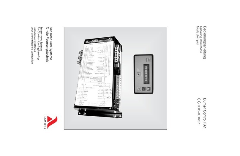
Lamtec FA1 User manual

www.lamtec.de
Sensors and Systems for Combustion Engineering
Quick Reference for Endusers
Burner Control FA1


2
Table of Contents
Table of Contents
1 General Information . . . . . . . . . . . . . . . . . . . . . . . . . . . . . . . . . . . . . . . . . . . . . . . . . . . . . . . . . 3
1.1 Validity of these Instructions . . . . . . . . . . . . . . . . . . . . . . . . . . . . . . . . . . . . . . . . . . . . . . 3
2 Safety . . . . . . . . . . . . . . . . . . . . . . . . . . . . . . . . . . . . . . . . . . . . . . . . . . . . . . . . . . . . . . . . . . . . 4
2.1 For Your Safety . . . . . . . . . . . . . . . . . . . . . . . . . . . . . . . . . . . . . . . . . . . . . . . . . . . . . . . . 4
3 Brief Description . . . . . . . . . . . . . . . . . . . . . . . . . . . . . . . . . . . . . . . . . . . . . . . . . . . . . . . . . . . 5
3.1 Life Cycle . . . . . . . . . . . . . . . . . . . . . . . . . . . . . . . . . . . . . . . . . . . . . . . . . . . . . . . . . . . . . 6
4 Customer Interface . . . . . . . . . . . . . . . . . . . . . . . . . . . . . . . . . . . . . . . . . . . . . . . . . . . . . . . . . 7
4.1 Display and Operational Controls . . . . . . . . . . . . . . . . . . . . . . . . . . . . . . . . . . . . . . . . . . 7
4.2 Contrast Settings . . . . . . . . . . . . . . . . . . . . . . . . . . . . . . . . . . . . . . . . . . . . . . . . . . . . . . . 7
4.3 Key Functions . . . . . . . . . . . . . . . . . . . . . . . . . . . . . . . . . . . . . . . . . . . . . . . . . . . . . . . . . 8
4.3.1 Initial State. . . . . . . . . . . . . . . . . . . . . . . . . . . . . . . . . . . . . . . . . . . . . . . . . . . . . . 8
4.3.2 Display Level 1 . . . . . . . . . . . . . . . . . . . . . . . . . . . . . . . . . . . . . . . . . . . . . . . . . . 8
4.3.3 Display Level 2 . . . . . . . . . . . . . . . . . . . . . . . . . . . . . . . . . . . . . . . . . . . . . . . . . . 9
4.3.4 Manual. . . . . . . . . . . . . . . . . . . . . . . . . . . . . . . . . . . . . . . . . . . . . . . . . . . . . . . . . 9
4.3.5 RESET. . . . . . . . . . . . . . . . . . . . . . . . . . . . . . . . . . . . . . . . . . . . . . . . . . . . . . . . . 9
5 Operating Unit . . . . . . . . . . . . . . . . . . . . . . . . . . . . . . . . . . . . . . . . . . . . . . . . . . . . . . . . . . . . 10
5.1 Use of the Operating Unit . . . . . . . . . . . . . . . . . . . . . . . . . . . . . . . . . . . . . . . . . . . . . . . 10
5.2 Connecting the Burner Control FA1 . . . . . . . . . . . . . . . . . . . . . . . . . . . . . . . . . . . . . . . . 10
6 Fault. . . . . . . . . . . . . . . . . . . . . . . . . . . . . . . . . . . . . . . . . . . . . . . . . . . . . . . . . . . . . . . . . . . . . 11
6.1 Reading Faults. . . . . . . . . . . . . . . . . . . . . . . . . . . . . . . . . . . . . . . . . . . . . . . . . . . . . . . . 11
6.2 Recalling Fault History . . . . . . . . . . . . . . . . . . . . . . . . . . . . . . . . . . . . . . . . . . . . . . . . . . 11
6.3 Resetting Faults . . . . . . . . . . . . . . . . . . . . . . . . . . . . . . . . . . . . . . . . . . . . . . . . . . . . . . . 11
7 Internal Burner Firing Rate Controller . . . . . . . . . . . . . . . . . . . . . . . . . . . . . . . . . . . . . . . . . 12
7.1 Purpose . . . . . . . . . . . . . . . . . . . . . . . . . . . . . . . . . . . . . . . . . . . . . . . . . . . . . . . . . . . . . 12
7.2 Moving Screen "Actual Temperature is too high". . . . . . . . . . . . . . . . . . . . . . . . . . . . . . 12
7.3 Changing Setpoint of Burner-Firing-Rate Controller . . . . . . . . . . . . . . . . . . . . . . . . . . . 12
7.4 Burner-Firing-Rate specified by hand . . . . . . . . . . . . . . . . . . . . . . . . . . . . . . . . . . . . . . 12
7.5 How to Change the Burner-Firing-Rate Controller with the Customer Interface . . . . . . 12
7.6 Displaying the Running Time Meter . . . . . . . . . . . . . . . . . . . . . . . . . . . . . . . . . . . . . . . . 13
7.7 Calling the Checksums . . . . . . . . . . . . . . . . . . . . . . . . . . . . . . . . . . . . . . . . . . . . . . . . . 14
8 Appendix. . . . . . . . . . . . . . . . . . . . . . . . . . . . . . . . . . . . . . . . . . . . . . . . . . . . . . . . . . . . . . . . . 15
8.1 Mode Abbreviations Used . . . . . . . . . . . . . . . . . . . . . . . . . . . . . . . . . . . . . . . . . . . . . . . 15
8.2 Fuses . . . . . . . . . . . . . . . . . . . . . . . . . . . . . . . . . . . . . . . . . . . . . . . . . . . . . . . . . . . . . . . 16
8.3 EU Declaration of Conformity . . . . . . . . . . . . . . . . . . . . . . . . . . . . . . . . . . . . . . . . . . . . 17

3
1 General Information
1.1 Validity of these Instructions
These instructions apply to the following device(s): FA1 in any configuration.
These devices conform to the following standards and regulations:
• DIN EN 298: 2012-11
• DIN EN 1643: 2014-09
• DIN EN 13611:2011-12
• DIN EN 60730-2-5: 2015-10
• DIN EN 60730-1:2012-10
• 2014/35/EU Low Voltage Directive
• 2014/30/EU EMC-Directive
• 2014/68/EU Pressure Equipment Directive
• (EU) 2016/426 Gas Appliance Directive
• 2011/65/EU RoHS
Test symbols: CE-0085 AU 0207
The FA1 is a control unit for combustion systems.
NOTICE
Respect the national safety regulations and standards.

4
2 Safety
2 Safety
2.1 For Your Safety
The following symbols are used in this document to draw the user's attention to important safe-
ty information. They are located at points where the information is required. It is essential that
the safety information is observed and followed, and that applies particularly to the warnings.
DANGER!
This draws the user's attention to imminent danger. If it is not avoided, it will result in death or
very serious injury. The plant including its surroundings could be damaged.
WARNING!
This draws the user's attention to the possibility of imminent danger. If it is not avoided, it may
result in death or very serious injury. The plant including its surroundings could be damaged.
CAUTION!
This draws the user's attention to the possibility of imminent danger. If it is not avoided, it may
result in minor injuries. The plant including its surroundings could be damaged.
NOTICE
This draws the user's attention to important additional information about the system or system
components and offers further tips.
The safety information described above is incorporated into the instructions.
Thus, the operator is requested to:
1 Comply with the accident prevention regulations whenever work is being carried out.
2 Do everything possible within his control to prevent personal injury and damage to prop-
erty.

5
3 Brief Description
3 Brief Description
The Burner Control FA1 is suitable for control of burners and combustion systems for gase-
ous, liquid and solid fuels, with permanent operation, also in hot air generators.
Connections for Interbus-S, PROFIBUS DP, CANopen, TCP/IP (Modbus TCP) and Modbus
RTU are available as optional equipment. The connection of other plant components e.g. O2
trim is by the LAMTEC SYSTEM BUS interface to a 9-pole Sub-D connector.
The operation is via optional PC software or programming unit. As display for end user, a cus-
tomer interface is connectable by LAMTEC SYSTEM BUS. The operation by PC software is
described in a separate manual
The FA1 continuously monitors its own functions and those of the connected control elements.
230 V outputs:
– actuation of the gas valves
– actuation of the oil valves
– actuation of the oil pump/rotary atomiser
– actuation of the ignition valve and the ignition transformer
– fan release
– fault message
– OPEN/CLOSE control signals (three-point-step or 4 ... 20 mA) for the mechanical fuel/air
ratio control
External signals to the FA1 are transmitted via floating contacts or chains of contacts.
The following signals can be pre-set:
– 3 separate safety interlock chains
– gas < max
– air pressure monitor
– pre-purge suppression
– minimum gas pressure monitor (for valve leakage test) gas >min
– flame signal
– burner on
– fuel selection
– oil pressure min / atomiser air pressure
– oil pressure max
– ignition position acknowledgement
– internal burner firing rate controller in combination with the control output

6
3 Brief Description
3.1 Life Cycle
FA1 Burner Control has a designed lifetime of 250,000 burner start-up cycles, which, under
normal operating conditions in heating mode, correspond to approx.
10 years of usage (starting from the production date given on the type plate).
This lifetime is based on the endurance tests specified in standard EN230/EN298 and the
table containing the relevant test documentation as published by the European Association of
Component Manufacturers (Afecor) (www.afecor.org).
The designed lifetime is based on use of BT300 according to the manufacturer’s basic docu-
mentation.After reaching designed lifetime in terms of number of burner start-up cycles, or the
respective time of usage, the BT300 must be replaced by authorized personnel.

7
4 Customer Interface
4.1 Display and Operational Controls
4.2 Contrast Settings
To adjust contrast values of the customer interface display use the arrow keys:
Fig. 4-1 Customer interface
Description of key functions:
→ RESET
→ Firing-rate/fault history up
→ Firing-rate/fault history down
→ MANUAL mode EIN/AUS
→ Umschaltung der Anzeige
– Fuel/air ratio control
– O2
– Flame intensity
– Operating hours
Fig. 4-2 Display with external burner-
firing-rate-controller
Fig. 4-3 Display in automatic mode Fig. 4-4 Display in manual mode
70 = setpoint of firing-rate controller
65 = actual value of internal firing-rate controller
600 = external firing-rate input
500 = internal firing-rate (current status of fuel/air ratio control)
These are sample values, which may differ from real situation.
Keep RESET key pressed and arrow key up = contrast value +2
Keep RESET key pressed and arrow key down = contrast value –2

8
4 Customer Interface
4.3 Key Functions
4.3.1 Initial State
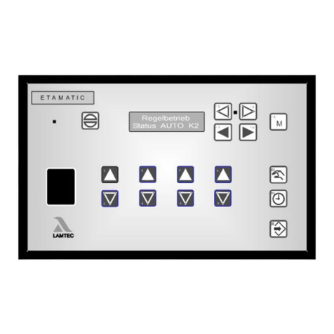
In the initial state (e.g. after power on) the display shows the condition of the ETAMATIC OEM
in the upper line (burner off, control operation, etc..) At the same time, queuing codes are cor-
rectly displayed ("Actuator runs")..
In the lower line of the display, it shows external and internal firing rate. If the parameter set-
tings of the burner firing rate controller is active, it shows setpoints and actual values of the
firing rate controller additionally.
In the initial state of the display (not on manual mode) while no fault of FA1 is pending, the
upper indicator line switches to:
First of all, the display shows an entry from the fault history including the error code and the
firing rate values.
The history display changes back to its prior display after 5 s.
Fault of the O2 controller, which lasts longer than 30 s would be saved.
After an idle time of 3 seconds, provided that there is no operation of the keys within this time,
the display shows a describing text of the selected entry. The describing text is copied behind
the error code. Both, error code and describing text are scrolling through the display.
Beispiel:
„ 1->H004 527 527 *** Flame fault during operation (Op.hours 000172)“
4.3.2 Display Level 1
Effect of the display level key
In the initial state of customer interface, this key indicates different operating values (even in
the event of an error).
The indications are called sequentially whenever you press the key:
press the RESET key, to change the primary status.
• Status display (operating mode) FA1
• Fault history entry 1
• ...
• ...
• ...
• Fault history entry 9
• Fault history entry 10
• O2-Fault history entry 20
• O2-Fault history entry 19
• ...
• ...
• ...
• O2-Fault history entry 2
• O2-Fault history entry 1
1 147 1 00 487
regular fault internal firing
rate
curve set operating hours

9
4 Customer Interface
NOTICE
If the mode „Setting firing rate controller“ is active (LED manual flashes) this key has no effect.
4.3.3 Display Level 2
4.3.4 Manual
Function of the manual key
In the HAND mode, the regular firing rate input of FA1 can be manually adjusted.
4.3.5 RESET
If the O2 trim is in fault condition and the lower display line shows the O2 value, the RESET-
key also resets the O2 trim.
In the customer interface the RESET–key effects as follows:
• Leaving the 2nd display level in the lower display line.
• Status report in the upper display line
• Disable manual-mode
• Deactivate mode „set burner firing rate controller“
• Display of operating mode (e.g. Burner OFF)
• Display of O2 value* (if activated)
• Flame intensity
• Operating hours
Press the key for more than 5 sec., the lower display line switches to the 2nd level. (see
chapter 7.7 Calling the Checksums).
Press the RESET Key to leave display level 2.
Press HAND key → LED in HAND key lights up
With these arrow keys the firing rate value can be adjusted.
Press HAND key to finish.
Faults can be reset through the RESET key.

10
5 Operating Unit
5 Operating Unit
5.1 Use of the Operating Unit
With the operating unit you may operate and the program the burner control system.
5.2 Connecting the Burner Control FA1
1. Connect the operating unit to the FA1 by using a 9-pin Cannon connector. To do so, use
the supplied connecting cable, type 663R0430.
Data transmission takes place by the LAMTEC SYSTEM BUS.
2. Alternatively:
Connect the operating unit with the cable of the customer interface. An adapter cable,
type 663R0426, is supplied for this purpose.
Disconnect the 6-pin connector from the customer interface and connect the adapter cable
to the 6-pin connector.
Fig. 5-1 Connection of the operating unit

11
6 Fault
6 Fault
6.1 Reading Faults
In initial state of customer interface (not MANUAL mode) while no fault state of FA1 occured
the upper line is switching over.
In case of a fault a current fault code and corresponding firing-rate values are shown. In the
next stage a marquee with the pending fault is displayed (see chapter 4.3.1 Initial State).
6.2 Recalling Fault History
The FA1 records the last 10 faults including the corresponding operating hours counter
value.
In initial state (not MANUAL mode), provided that no fault message of the FA1 is pending, the
upper display line is switching over:
6.3 Resetting Faults
NOTICE
This may result in a RESET of the O2 trim when a fault of O2 trim is pending (see chapter 4.3.5
RESET).
Contact your service provider in an event of a fault.
You may read off the display values using the SHIFT key (e.g. of operating hours, time)
in the event of a fault. All display values are frozen.
You may scroll through the fault history using the arrow keys.
See also chapter 4.3.1 Initial State.
Press the RESET key to reset a fault of FA1.

12
7 Internal Burner Firing Rate Controller
7.1 Purpose
The internal firing rate controller calculates the burner firing rate against a pre-defined setpoint
value (e.g. as a function of temperature or pressure) by comparison with the actual value. This
position will be transferred to the electronic fuel/air ratio control as a default value.
7.2 Moving Screen "Actual Temperature is too high"
7.3 Changing Setpoint of Burner-Firing-Rate Controller
see chapter 7.5 How to Change the Burner-Firing-Rate Controller with the Customer Interface
7.4 Burner-Firing-Rate specified by hand
It is also possible to switch the FA1 to "Manual Control" with the terminals. By short-circuiting
the Pt100 signal (e.g. bridge terminal 19 and 20) the burner firing rate controller is switched
off. The fuel/air ratio controller then directly follows the input at the default firing rate input. The
display shows LE instead of HA.
NOTICE
Only use manual control while monitoring the system.
7.5 How to Change the Burner-Firing-Rate Controller with the Customer Interface
Keep pressing the HAND key for more than 5sec., to switch the customer interface to the
mode „set setpoints of burner firing rate controller“. This is only possible when burner firing
rate controller is activated. At the same time, the HAND mode for manual firing rate input ends.
In the mode „setting firing rate controller“ the LED in the manual-key flashes. The lower display
line shows the output regulator adjustment, the setpoint value and the actual value.
Active constant controller:
The Gerät can be started nevertheless by pressing the manual mode key provided that
the maximum temperature is not exceeded.
By pressing the manual mode key once more you switch to AUTO mode.
Press key MANUAL to move the regular firing rate input of the firing rate controller.
Press the keys 2 and 3 to variegate the burner firing rate.
Press key MANUAL again to cancel firing rate controller.
Press the key for 5 s long. Display = actual setpoint 1 or 2.
This depends on the choice of setpoint values of terminal 50:
Terminal 50 = 0 V = setpoint value 1
Terminal 50 = 24 V = setpoint value 2

13
7 Internal Burner Firing Rate Controller
Active control by atmospheric condition:
7.6 Displaying the Running Time Meter
NOTICE
The sum of operating hours curve set 1 and curve set 2 do not result automatically in the value
of operating hours which are displayed in total.
The counter refers to the total sum of operating hours of FA1. It is started as soon as voltage
is applied to the device (this counter also provides basic data to fault history).
The operation hours counter refers to the operating hours of the burner. It starts to run as soon
as the burner is in operation with the corresponding curve set (Flame signal is applied).
The required setpoint values can be set through the arrow keys.
Press HAND or RESET key to leave the SET BURNER FIRING RATE CON-
TROLLER mode.
Press the key for 5 s long. Display = actual setpoint 1 or 2 and actual value.
This depends on the choice of setpoint values of terminal 50:
Terminal 50 = 0 V = setpoint value 1
Terminal 50 = 24 V = setpoint value 2
Re-press the key. Display = "LowVal" and actual lower setpoint value.
The lower setpoint value can be set through the arrow keys.
Re-press the key. Display = "HighVal" and actual upper setpoint value.
The upper setpoint value can be set through the arrow keys.
Press HAND or RESET key to leave the SET BURNER FIRING RATE CON-
TROLLER mode.
Press SHIFT key to call operating hours on display.
The display shows alternately:
– The operating hours would be scrolled automatically after 3 s.
– Op.hours: 000000 (Total)
– Burner.1: 000000 (burner 1 Op.hours)
Plant 1: 000000 (burner 1 no. of starts)
– Burner 2: 000000 (burner 2 Op.hours)
Plant 2: 000000 (burner 2 no. of starts)
– At 2 oil curves, burner 1 + burner 3 instead of burner.2
– At 2 gas curves, burner 2 + burner 4 instead of burner 2

14
7 Internal Burner Firing Rate Controller
7.7 Calling the Checksums
When parameters are changed, the check sums can only be refreshed after the restart of the
device.
If two customer interfaces were installed at the LSB the check sums may only be called when:
• simultaneously pressing at both customer interfaces the shift key for a long time
or
• one customer interfaces is disconnected temporarily.
Keep pressed the SHIFT key for a long time.
→One after the other is shown:
CRC 16 of level 0, 1 and 2→ changeable by authorised personnel only
CRC 16 der Ebene 4 → changeable by LAMTEC only
1. safety time oil in s
2. safety time oil in s
1. safety time gas in s
2. safety time gas in s
Pre-purge period in s
Press the SHIFT key at the customer interface to abort the process.

15
8 Appendix
8 Appendix
8.1 Mode Abbreviations Used
Fig. 8-1 Status display at customer interface Fig. 8-2 Display at programming unit
Short text Description
BE → READY (signal on terminal 58)
ZÜ → IGNITION POSITION or IGNITION
EZ → SETTING/IGNITION position (same as IGNITION, but FA1 on SET-
TING)
GL → BASE FIRING RATE
EG → SETTING/BASE FIRING RATE” (as BASIC FIRING RATE, but FA1 on
SETTING)
NA → POST-PURGE
AU → BURNER OFF (no signal present)
EL → SETTING
SL → CLEAR MEMORY
EV → SETTING/PRE-PURGE" (as "PRE-PURGE", but FA1 on SETTING)
ES → SETTING/CONTROL (as AUTOMATIC but FA1 on SET)
ST → FAULT
VO → PRE-PURGE
HA
or Hand
→ MANUAL MODE (burner efficiency may be adjusted manually)
no display → Burner set to AUTOMATIC during OPERATION
LE → EXTERNAL FIRING RATE (firing rate controller disabled by digital
input)

16
8 Appendix
8.2 Fuses
NOTICE
PC connection possible only via LAMTEC interface adapter!
NOTICE
For exchange of the fuses F3, F4, F5 these specifications are to be complied:
- 2A slow blow
- high breaking capacity according to IEC 60127-2, Sheet 5: 1500A @ 250VAC
- melting integral I²t < 40 A²s
- e.g. Littelfuse 0215002.(M)XP
Fuses which fulfills these requirements are ceramic tube fuses with the label T2AH 250V.
Fig. 8-3 Rear view FA1
F1 Gerät
F2 Control elements
F3 Main gas 1, oil, oil pump
F4 Main gas 2, pilot valve, ignition
transformer
F5 Fan, fault indication
F6 24 VDC
S1 9-pole Sub-D connector for
LAMTEC SYSTEM BUS
S2 Communications interface

17
8 Appendix
8.3 EU Declaration of Conformity

18
8 Appendix

19
8 Appendix
Other manuals for FA1
2
Table of contents
Other Lamtec Controllers manuals
Popular Controllers manuals by other brands

RLE Technologies
RLE Technologies SeaHawk LD5200 user guide

SpaGuts
SpaGuts VS500SZ-Series Operation guide

Osram
Osram EASY Fitting instructions

Jandy
Jandy AquaLink Touch Installation and operation manual

Buderus
Buderus Logamatic SC40 Installation and servicing instructions

EMKO
EMKO Trans-midiAUTO.MPU.232... manual