PTZOptics Move 4K User manual


2
v1_1 rev. 10-22
Preface .......................................................... 3
Precautions . . . . . . . . . . . . . . . . . . . . . . . . . . . . . . . . . . . . . . . . . . . . . . . . . . . . . . . 3
Warning .......................................................... 3
Warranty ......................................................... 4
Supplied Accessories . . . . . . . . . . . . . . . . . . . . . . . . . . . . . . . . . . . . . . . . . . 4
FCC Statement .............................................. 4
Copyright Notice ............................................. 4
NDI®|HX with NDI® 3 Connection ..................................... 5
Features ......................................................... 7
Technical Specications ............................................. 8
Dimensions ....................................................... 11
IR Remote Controller Guide .......................................... 12
Serial Communication Control......................................... 14
On Screen Display. . . . . . . . . . . . . . . . . . . . . . . . . . . . . . . . . . . . . . . . . . . . . . . . . . 25
Network Connection ................................................ 29
Web UI........................................................... 32
Maintenance and Troubleshooting ..................................... 47
Unqualied Applications . . . . . . . . . . . . . . . . . . . . . . . . . . . . . . . . . . . . . . . . 47
Troubleshooting .............................................. 4

3v1_1 rev. 10-22
Preface
Congratulations on receiving your new PTZOptics Move 4K Camera. This manual introduces the
function, installation, and operation of the HD camera. Prior to installation and usage, please read the
manual thoroughly. If you have any questions or issues with this process, please contact our Support
Team.
Precautions
This product can only be used in the specied conditions in order to avoid any damage to the unit
itself.
• Don’t subject the camera to rain or moisture.
• Don’t remove the cover. Removal of the cover may result in an electric shock. In addition to
• Never operate outside of the specied operating temperature range, humidity, or with any other
power supply than the one originally provided with the unit.
• Please use a soft dry cloth to clean the unit. If the unit is very dirty, clean it with diluted neutral
detergent; do not use any type of solvents which may damage the surface.
Warning
• Electrical Safety
Installation must be in accordance with national and local electric safety standards. Do
not use any power supply other than the one originally supplied with this camera.
• Polarity of Power Supply
The power supply output for this product is 12V DC with a maximum current supply of
2A. Polarity of the power supply plug is critical and is as follows:
• Handling
ŜAvoid any stress, vibration, or moisture during transportation, storage, installation,
and operation.
ŜDo not lift or move the camera by grasping the camera head. Do not turn the camera
head by hand. Doing so may result in mechanical damage.
ŜDo not expose the camera to any corrosive solid, liquid, or gas to avoid damage to
the cover which is made of a plastic material.
ŜEnsure that there are no obstacles in the pan or tilt ranges of the camera lens.
ŜNever power down the camera on before installation is complete.
• Do not dismantle the camera – PTZOptics is not responsible for any unauthorized
modication or dismantling.

4
v1_1 rev. 10-22
Supplied Accessories
When you unpack your camera, check that all the supplied
accessories are included:
▪Camera 1
▪AC Power Supply 1
▪USB A-A Cable 1
▪RS232 Cable 1
▪IR Remote 1
▪AAA Batteries 2
▪Quick Start Guide 1
FCC Statement
This equipment has been tested and found to comply with the limits for a Class A digital device,
pursuant to part 15 of the FCC Rules. These limits are designed to provide reasonable protection
against harmful interference when the equipment is operated in a commercial environment. This
equipment generates, uses, and can radiate radiofrequency energy and, if not installed and used in
accordance with the instruction manual, may cause harmful interference to radio communications.
FCC Caution: Any changes or modications not expressly approved by the party responsible for
compliance could void the user’s authority to operate this equipment. Operation is subject to the
following two conditions: This device may not cause harmful interference, and (2) this device must
accept any interference received, including interference that may cause undesired operation.
• Warning - This is a class A product. In a domestic environment, this product may cause
radio interference in which case the user may be required to take adequate measures.
• Remote Control Battery Safety Information - Store batteries in a cool and dry place.
Do not throw away used batteries in the trash. Properly dispose of used batteries through
specially approved disposal methods. Remove the batteries if they are not in use for long
periods of time. Battery leakage and corrosion can damage the remote control. Do not use
old batteries with new batteries. Do not mix and use dierent types of batteries: alkaline,
standard (carbon-zinc) or rechargeable (nickel-cadmium). Do not dispose of batteries in a
re. Do not attempt to short-circuit the battery terminals.
Copyright Notice
The entire contents of this manual / guide, whose copyright belongs to PTZOptics, may not be cloned, copied, or translated in any way
without the explicit permission of the company. The product specications referred to in this document are for reference only and as
such are subject to updating at any time without prior notice.
©2022 | PTZOptics | All Rights Reserved
Warranty
PTZOptics includes a limited parts & labor warranty for all PTZOptics manufactured
cameras. The warranty is valid only if PTZOptics receives proper notice of such defects during the
warranty period. PTZOptics, at its option, will repair or replace products that prove to be
defective. PTZOptics manufacturers its hardware products from parts and components that are new
or equivalent to new in accordance with industry standard practices.

5v1_1 rev. 10-22
NDI®|HX Connection
The NDI®|HX connection allows you to connect and control your camera through any NDI
compatible hardware or software on your Local Area Network. Once your camera is setup on a LAN,
you can utilize the NDI®|HX connection.
NDI®|HX Setup:
1. Download and install the latest NDI®|HX Tools from https://www.ndi.tv/tools.
2. Congure your camera settings from the NDI Cong tab in the camera’s web
interface.
3. Select your camera within the NDI®|HX compatible device.
4. Select your camera. The NDI feed will utilize the camera’s device friendly name.
NewTek® NDI®, NDI® 4 & NDI®|HX are all registered trademarks by NewTek®.
Please note that your NDI License key is non-transferrable.
6
v1_1 rev. 10-22
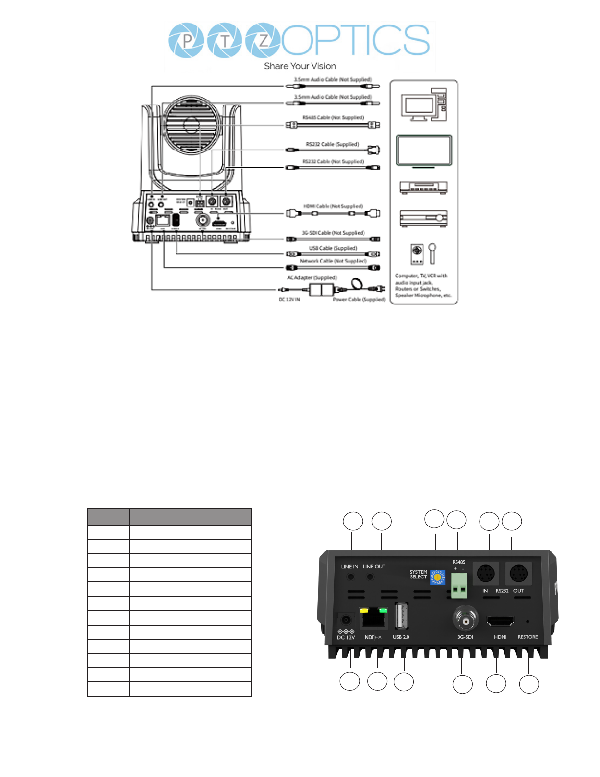
Item Number
1 Line In
2 Line Out
3 Resolution Dial
4 RS485 Interface
5 RS232 IN Interface
6 RS232 OUT Interface
7 DC 12V
8 LAN (PoE)
9 USB 2.0
10 3G-SDI
11 HDMI
12 Restore
Connection Guide
Please check connections are correct before starting.
Connect the power adapter to the power connector on the rear panel of the camera. The power
indicator on the front panel of the camera will be on.
After the camera is powered on, it starts to initialize. It will rotate to the left and right limit positions,
and then both horizontal and vertical limit positions. It will then stop at the center position. When the
motor stops running, and the initialization is complete.
(Note: If preset 0 is saved, PTZ will be move to preset 0)
123456
78910 11 12

7v1_1 rev. 10-22
Features
• Built-In Auto-Tracking
Advanced AI algorthms to enable auto tracking in various scenarios such as education,
conerences and live broadcasts.
• 4K 60 fps
UltraHD 4K (3840x2160p) video resolutions up to 60 FPS.
• Tally Light
Features a built-in tally light he light shines GREEN to indicate when the camera is in preview
mode. The light shines RED when the camera is on-air. The tally light illuminates when it’s being
used with NDI-compatible video mixing software.
• HDMI 2.0
Supports HDMI 2.0, can directly output 4K uncompressed digital video.
• Photobooth Functionality
Save short videos and photos directly to the camera.
• Low Light
CMOS image sensor with ultra-high SNR can reduce image noise in low light.
• 3D Noise reduction
Produces a clean, clear image even in low light and the signal-to-noise ratio is as high as 55dB.
• Built-in Gravity Sensor
Supports automatic image ip function, convenient installation and use of engineering.
• Audio Embedding
Line-level audio can be embedded over every video output.
• Multiple Interfaces
Supports HDMI 2.0 or 3G-SDI, LAN, & USB 2.0.
(HDMI & SDI are not simultaneous.)
• Remote Control
Can be controlled through the IR remote, network connection, as well as the RS232, RS485,
and the USB port.

8
v1_1 rev. 10-22
Model PT20X-4K-WH-G3 / PT20X-4K-GY-G3
Type PTZOptics Move 4K
Description 4K60 PTZ camera with auto tracking & HDMI, SDI, USB, & IP video
outputs
Resolution & Frame Rate HDMI: 2160p-60/59.94/50/30/29.97/25, 1080p-60/59.94/50/30/29.97/25, 1080i-
60/59.94/50, 720p-60/59.94
SDI: 1920x1080p-60/59.94/50/30/29.97/25, 1920x1080i-60/59.94/50,
1280x720p-60/59.94
Sensor 1/1.8 inch, CMOS, Eective pixels: 8.42M
Scanning Mode Progressive
Lens f = 6.25mm ~ 125mm, F1.58 ~ F3.95
Digital Zoom O (3840x2160), 2X (1920x1080), 3X (1280x720), 4X, (960x540), 8X
(480x270), 16X (256x144)
Video Based Auto Tracking Supported
Audio Based Auto Tracking Not Supported
Minimum Illumination 0.5 Lux @ (F1.8, AGC ON)
Shutter 1/30s ~ 1/10000s
White Balance Auto, Indoor, Outdoor, One Push, Manual, VAR
Backlight Compensation Supports
Digital Noise Reduction 3D Digital Noise Reduction
Video Signal Noise Reduction ≥55dB
Horizontal Angle of View 3.5° ~ 60.7°
Vertical Field of View 1.89° ~ 34.1°
Horizontal Rotation Range ±170°
Vertical Rotation Range -30° ~ +90°
Pan Speed Range 1.7° ~ 100°/s
Tilt Speed Range 1.7° ~ 69.9°/s
Image Flip Supported (built-in gravity sensor)
Image Mirror Supported
Image Freeze Supported
PoE Supported
Preset Accuracy 0.1⁰
Technical Specications

9v1_1 rev. 10-22
USB Features
Operating System Windows 7 / 8.1 / 10 / 11 / Mac OS, Linux, Android
Color System/Compression YUY2 / MJPEG / H.264 / H.265
Video Format YUY2: Max resolution: 3840x2160@5
H264: Max resolution: 3840x2160@30
H265: Max resolution: 3840x2160p@30
MJPEG: Max resolution: 3840x2160p@30
USB Audio Supported
UVC Version UVC 1.1 ~ 1.5
UVC Control Supported
IP Video Features
Video Compression H.264, H.265, MJPEG
Video Stream First Stream, Second Stream
First Stream Resolutions 3840x2160, 1920x1080, 1280x720, 1024x576, 720x480, 720x408,
640x480, 640x360
Second Stream Resolutions 720x480, 720x408, 640x480, 640x360, 480x320, 320x240
Video Bitrate First Stream: 32kbps ~ 102400kbps
Second Stream: 32kbps ~ 20480
Bit Rate Type Constant Bit Rate (CBR), Variable Bit Rate (VBR)
Frame Rate 50Hz: 1 ~ 50 fps
60Hz: 1 ~ 60 fps
Audio Compression AAC
Audio Bit Rate 96kbps, 128kbps
Supported Protocols TCP/IP, UDP, HTTP, RTSP, RTMP/RTMPS, ONVIF, NDI®|HX, SRT,
Multicast, etc.
Input / Output Interface
HD Output 1x RJ45: 10/100/1000M Adaptive Ethernet Port
1x HDMI: version 2.0
1x USB 2.0: type A
1x 3G-SDI: BNC type, 800mVP-p, 75Ω, Along to SMPTE 424M
standard
Audio Interface 1x 3.5mm Line level Input
1x 3.5mm Line level Output
Communication Interface 1x 8-pin Mini DIN RS232 Input, Max distance: 98.5ft / 30m, Protocol: VISCA
/ Pelco-D / Pelco-P
1x 8-pin Mini DIN RS232 Output, Max distance: 98.5ft / 30m,
Protocol: VISCA / Pelco-D / Pelco-P
1x 2-pin Phoenix port RS485 Input / Output, Max distance: 3,937ft / 1200m,
Protocol: VISCA / Pelco-D / Pelco-P
IR 4x IR Addresses, Max distance 30ft / 9m
Power Jack JEITA type (DC IN 12V)

10
v1_1 rev. 10-22
Physical Parameter
Input Voltage DC 12V / PoE(802.3af)
Current Consumption Max 2A
Operating Temperature 14°F ~ 104°F (-10°C ~ 40°C)
Storage Temperature -40°F ~ 140°F (-40°C ~ 60°C)
Humidity Range 10% - 80%
Power Consumption Max 18W
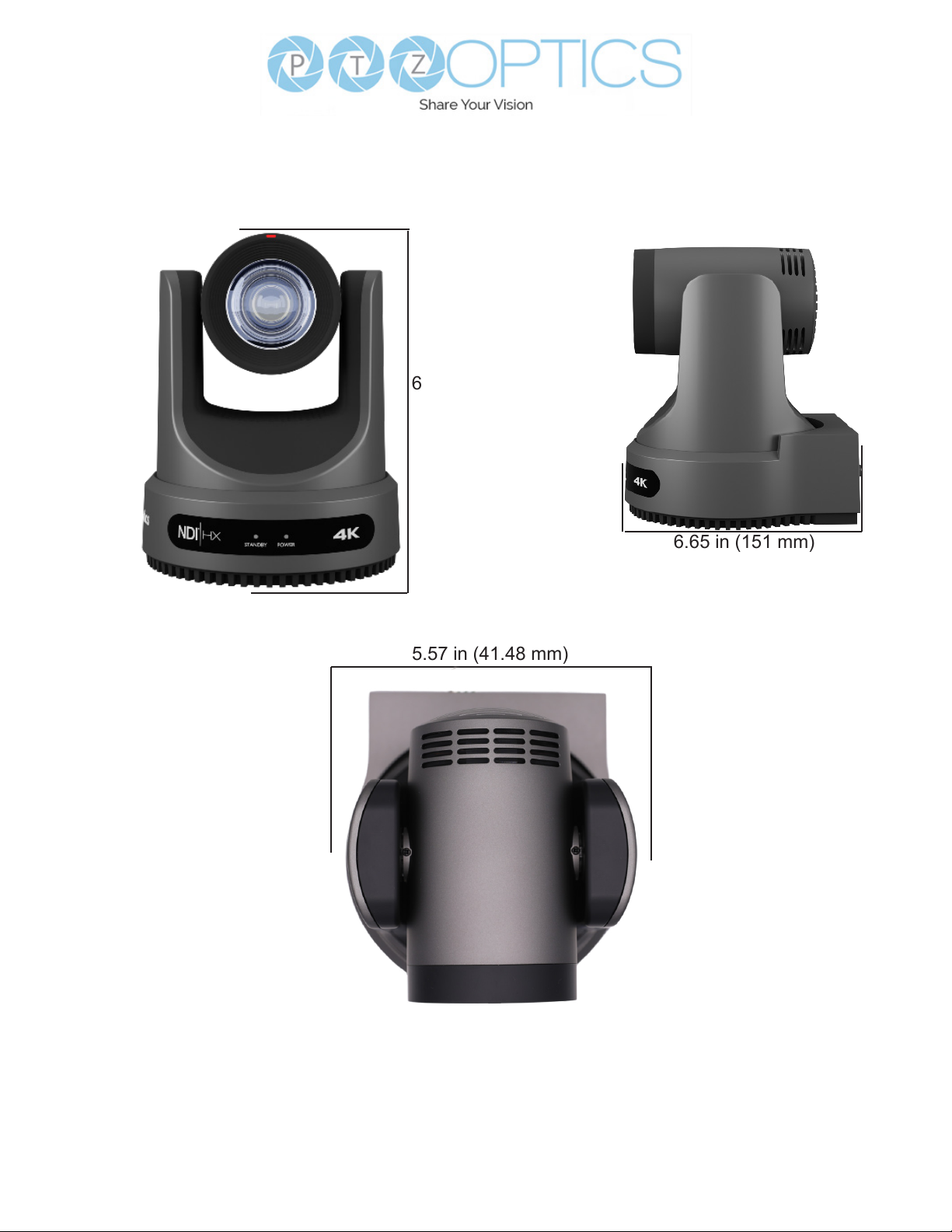
Size in. (W x D x H) 5.57” W x 5.94” (6.65” including SDI) D x 6.93” (7.91” with tilt up) H
Size mm. (W x D x H) 141.48mm W X169mm (including SDI) D x 176mm (201mm with
tilt up) H
Camera Weight 3.25 lbs | 1.47kg
11 v1_1 rev. 10-22
Dimensions
6.65 in (151 mm)
6.93 in, (176 mm)
5.57 in (41.48 mm)
12
v1_1 rev. 10-22
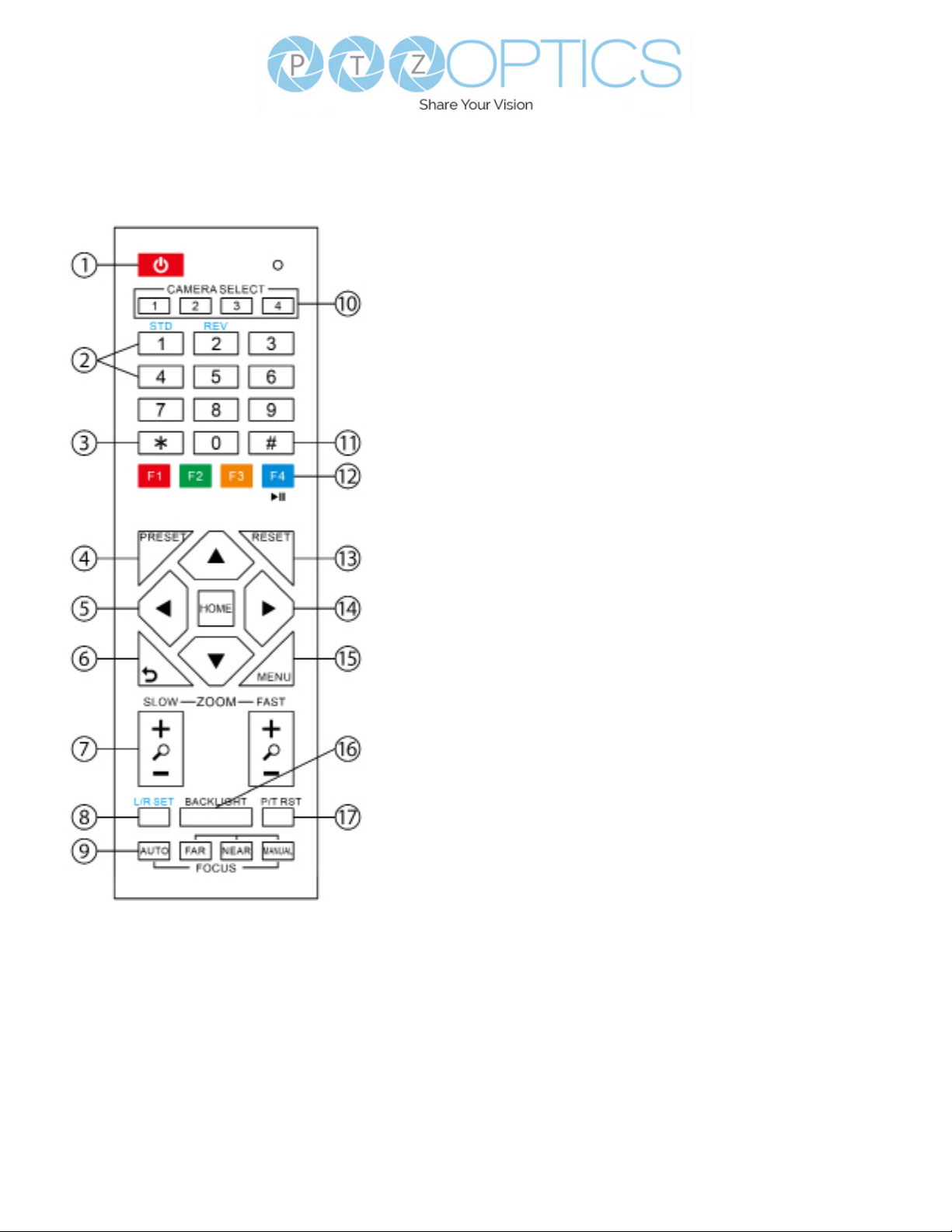
IR Remote Controller
Guide
1. Standby Button
Press this button to enter standby mode.
Press it again to enter normal mode.
Note: Power consumption in standby
mode is approximately half of the normal
mode.
2. Position Buttons
To set or call preset position.
3. * Button
For multiple functions. Typically used when
calling shortcuts.
4 & 13. Set / Clear Preset Buttons
Set Preset: Store a preset position
[PRESET] + Numeric button (0-9):
Setting a corresponding numeric key
preset position.
Clear Preset: Erase a preset position.
[RESET] + Numeric button (0-9) or; [*] +
[#] + [RESET]: Erase all presets
5 & 14. Pan / Tilt Control Buttons
Press the arrow buttons to perform
panning and tilting. Press the [HOME]
button to face the camera back to the
front. (PTZ Cameras Only)
6. Return Button
Press the [RETURN] button to go back
a previous menu within the OSD menu.
7. Zoom Buttons
Zoom+: Zoom In (Slow and fast speed).
Zoom-: Zoom Out (Slow and fast
speed).
8. L / R Set Buttons
Set the Left & Right direction of the
remote control.
[L/R SET] + [1]: Normal direction
[L/R SET] + [2]: Left and right directions
will be reversed.
Press buttons simultaneously.
9. Focus Buttons
Used for focus adjustment.
[AUTO]: Automatically focus image on
the center object.
[MANUAL]: Allow for manual control
of focus. Make adjustments using [FAR]
(focus on far object) and [NEAR] (focus
on near object).
10. Camera Address Select Buttons
Press the camera select button
corresponding to the camera in which
you want to operate.

13 v1_1 rev. 10-22
11. # Button
For multiple functions. Typically used
when calling shortcuts
12. Multiple Function Buttons
Function 1. For setting camera IR
address.
Press 3 keys at the same time to set the
camera IR address as follows:
[*] > [#] > [F1]: Address 1
[*] > [#] > [F2]: Address 2
[*] > [#] > [F3]: Address 3
[*] > [#] > [F4]: Address 4
Function 2. Image Freeze function
Press [F4] to enable Image Freeze. After
enabled, “Freeze” will be displayed in
the upper left corner for 5 seconds.
To disable Image Freeze, press [F4] again.
15. Menu Settings
For adjusting the camera On Screen
Display (OSD) Menu settings
[MENU]: Open or close the On Screen
Display menu
16. Backlight Button
Use to enable or disable backlight
compensation.
Note: Only eective in auto exposure
mode.
Note: If there is light behind the subject,
they may appear darker. In this case, use
Backlight Compensation to enhance
image.
17. P / T RST Button
Perform camera self-calibrate pan and tilt
movement. (PTZ Cameras Only)
18. Shortcut Functions
[*] > [#] > [1]: Display OSD menu in
English
[*] > [#] > [3]: Display OSD menu in
Chinese
[*] > [#] > [4]: Show IP address
[*] > [#] > [6]: Quickly restore the
default settings
[*] > [#] > [8]: Show the camera version
[*] > [#] > [9]: Quickly set mount mode
(ip / normal)
[*] > [#] > [MANUAL]: Resets IP
information to default
[#] > [*] > [4]: Enable Dynamic IP address
[#] > [*] > [#] > [1]: Sets IP address to
192.168.100.81
[#] > [*] > [#] > [2]: Sets IP address to
192.168.100.82
[#] > [*] > [#] > [3]: Sets IP address to
192.168.100.83
[#] > [*] > [#] > [4]: Sets IP address to
192.168.100.84
[#] > [*] > [#] > [5]: Sets IP address to
192.168.100.85
[#] > [*] > [#] > [6]: Sets IP address to
192.168.100.86
[#] > [*] > [#] > [7]: Sets IP address to
192.168.100.87
[#] > [*] > [#] > [8]: Sets IP address to
192.168.100.88
[#] > [*] > [#] > [9]: Sets IP address to
192.168.100.89
[#] > [*] > [#] > [0]: Sets IP address to
192.168.100.80

14
v1_1 rev. 10-22
No. Function
1 DTR
2 DSR
3 TXD
4 GND
5 RXD
6 GND
7 IR OUT
8 NC
Camera Windows DB-9
1.DTR 1.CD
2.DSR 2.RXD
3.TXD 3.TXD
4.GND 4.DTR
5.RXD 5.GND
6. Unused 6. DSR
7. Unused 7. Unused
8. Unused 8.Unused
9. Unused 9. Unused
Camera Mini DIN
1. DTR 1. DTR
2 DSR 2. DSR
3. TXD 3. TXD
4. GND 4. GND
5. RXD 5. RXD
6. Unused 6. Unused
7. Unused 7. Unused
8.Unused 8. Unused
RS-232 Interface
For Initial Connection For Daisy Chain Control
RS232 Communication Control
This camera can be controlled vis RS-232. The Parameters for RS-232C are as follows:
Baud Rate: 2400, 4800, 9600 or 38400 bps
Start Bit: 1 bit
Data Bit: 8 bits
Stop Bit: 1 bit
Parity Bit: None
Serial Communication Control

15 v1_1 rev. 10-22
To utilize an RS-485 connection, you will need an unterminated two conductor cable.
1. Connect the positive (red) wire to the camera’s positive phoenix connector port (left).
2. Connect the negative (black) wire to the camera’s negative phoenix connector port (right).
3. Connect the positive and negative wires to the positive and negative ports on your joystick
controller.
ŜTo connect multiple cameras, you have the option to connect via daisy-chain or home run.
4. In either method, multiple wires will be connected to a single phoenix connector port.
RS-485 Daisy-Chain connection RS-485 Home Run connection
RS-485 Interface
The left phoenix connector port is Positive (+)
The right phoenix connector port is Negative (-)
The camera can be controlled via RS-485, Half-
duplex mode, with support for VISCA, Pelco-D, or
Pelco-P protocol. The parameters of RS485 are
as follows:
RS-485 Communication Control
Baud rate: 2400/4800/9600/38400;
Starting position: 1 bit
Data bit: 8 bits
Stop bit: 1 bit
Check digit: None

16
v1_1 rev. 10-22
Part 1: Camera Issued Commands
ACK / Completion Messages
Command Function Command Packet Comments
ACK / Completion Messages
ACK
z0 4y FF
(y: Socket No.)
Returned when the command is accepted.
Completion z0 5y FF
(y: Socket No.)
Returned when the command has been
executed.
Error Messages
Command Function Command Packet Comments
Error Messages
Syntax Error
z0 60 02 FF Returned when the command format is dierent or
when a command with illegal command parameters is
accepted.
Command Buer Full
z0 60 03 FF Indicates that two sockets are already being used
(executing two commands) and the command could not
be accepted when received
Command Canceled
z0 6y 04 FF
(y: Socket No.)
Returned when a command which is being executed in
a socket specied by the cancel command is canceled.
The completion message for the command is not
returned.
No Socket
z0 6y 05 FF
(y: Socket No.)
Returned when no command is executed in a socket
specied nu the cancel command, or when an invalid
Socket No. is specied
Command Not Executable
z0 6y 41 FF
(y: Execution command
Socket No. Inquiry
command: 0)
Returned when a command cannot be executed due
to current conditions. For example: when commands
controlling the focus manually are received during auto
focus mode.
VISCA over IP control: z = 9
Serial VISCA control: z = Camera Address + 8
Part 2:PTZOptics Command List
Command Function Command Packet Comments
IF Clear Broadcast 8x 01 00 01 FF I/F Clear
CAM_Power
On 8x 01 04 00 02 FF Power On/O
O 8x 01 04 00 03 FF
CAM_Zoom
Stop 8x 01 04 07 00 FF
Tele (Standard) 8x 01 04 07 02 FF
Wide (Standard) 8x 01 04 07 03 FF
Tele (Variable) 8x 01 04 07 2p FF p = 0 (low) – 7 (high)
Wide (Variable) 8x 01 04 07 3p FF
Direct 8x 01 04 47 p q r s FF
PTZOptics Serial VISCA & VISCA over IP Command List

17 v1_1 rev. 10-22
CAM_Focus
Stop 8x 01 04 08 00 FF
Far (Standard) 8x 01 04 08 02 FF
Near (Standard) 8x 01 04 08 03 FF
Far (Variable) 8x 01 04 08 2p FF p = 0 (low) – 7 (high)
Near (Variable) 8x 01 04 08 3p FF
Direct 8x 01 04 48 0p 0q 0r 0s FF
pqrs: Zoom Position
(0x04 0x00 0x00 0x00 = Full Zoom in.
0x00 0x00 0x00 0x00 = Full Zoom out.)
Auto Focus 8x 01 04 38 02 FF
Auto Focus On / OManual Focus 8x 01 04 38 03 FF
Auto / Manual 8x 01 04 38 10 FF
Snap Focus 8x 01 04 38 04 FF Focus image while maintaining manual
focus mode.
Focus Lock 8x 0a 04 68 02 FF Prevents any other operation or
command from adjusting the current
focus state.
Focus Unlock 8x 0a 04 68 03 FF
CAM_AFSensitivity
High 8x 01 04 58 01 FF
AF Sensitivity High / Normal / LowNormal 8x 01 04 58 02 FF
Low 8x 01 04 58 03 FF
CAM_WB
Auto 8x 01 04 35 00 FF Normal Auto mode
Indoor 8x 01 04 35 01 FF Indoor mode
Outdoor 8x 01 04 35 02 FF Outdoor mode
OnePush 8x 01 04 35 03 FF One Push White Balance mode
Manual 8x 01 04 35 05 FF Manual control mode
ColorTemperature (VAR) 8x 01 04 35 20 FF Color Temperature mode
OnePush Trigger 8x 01 04 10 05 FF One Push White Balance Trigger
CAM_RGain
Reset 8x 01 04 03 00 FF Default Bright position
Up 8x 01 04 03 02 FF
Down 8x 01 04 03 03 FF
Direct 8x 01 04 43 00 00 0p 0q FF pq: Red Gain
CAM_BGain
Reset 8x 01 04 04 00 FF Manual control of blue gain
Up 8x 01 04 04 02 FF
Down 8x 01 04 04 03 FF
Direct 8x 01 04 44 00 00 0p 0q FF pq: Blue Gain
CAM_ColorTemp
Reset 8x 01 04 20 00 FF Default ColorTemperature settings
Up 8x 01 04 20 02 FF
Down 8x 01 04 20 03 FF
Direct 8x 01 04 20 0p 0q FF pq: ColorTemperature position: 0x00:
2500K ~ 0x37: 8000K
CAM_RTuning Direct 8x 0A 01 12 pq FF pq: Red / Blue Tuning position 0x00
(-10) ~ 0x14 (+10)
CAM_BTuning Direct 8x 0A 01 13 pq FF
CAM_AE
Full Auto 8x 01 04 39 00 FF Automatic Exposure mode
Manual 8x 01 04 39 03 FF Manual exposure mode
Shutter Priority 8x 01 04 39 0A FF Shutter priority auto exposure mode
Iris Priority 8x 01 04 39 0B FF Iris priority auto exposure mode
Bright 8x 01 04 39 0D FF Bright manual exposure mode

18
v1_1 rev. 10-22
CAM_Iris
Reset 8x 01 04 0B 00 FF Default Iris position
Up 8x 01 04 0B 02 FF
Iris setting
Down 8x 01 04 0B 03 FF
Direct 8x 01 04 4B 00 00 0p 0q FF pq: Iris position
CAM_DRC Direct 8x 01 06 01 0E 0E 03 02 FF p: 0(low) - 8(high)
CAM_Shutter
Reset 8x 01 04 0A 00 FF Default shutter position
Up 8x 01 04 0A 02 FF
Shutter setting
Down 8x 01 04 0A 03 FF
Direct 8x 01 04 4A 00 00 0p 0q FF pq: Shutter position
CAM_Gain
Reset 8x 01 04 0C 00 FF Gain Setting
Up 8x 01 04 0C 02 FF
Down 8x 01 04 0C 03 FF
Direct 8x 01 04 0C 00 00 0p 0q FF pq: Gain Position
Gain Limit 8x 01 04 2C 0p FF p: Gain Position
CAM_Bright
Reset 8x 01 04 0D 00 FF Default Bright position
Up 8x 01 04 0D 02 FF Bright setting
Down 8x 01 04 0D 03 FF
Direct 8x 01 04 0D 00 00 0p 0q FF pq: Bright position
CAM_ExpComp
On 8x 01 04 3E 02 FF Exposure Compensation On / O
O 8x 01 04 3E 03 FF
Reset 8x 01 04 0E 00 FF Default ExpComp position
Up 8x 01 04 0E 02 FF ExpComp setting
Down 8x 01 04 0E 03 FF
DIrect 8x 01 04 4E 00 00 0p 0q FF pq: ExpComp position
CAM_NR(2D)Mode Auto 8x 01 04 50 02 FF ND2D Auto/Manual
Manual 8x 01 04 50 03 FF
CAM_NR(2D)Level Direct 8x 01 04 53 0p FF p: NR Setting (0: O, level 1 to 5)
CAM_NR(3D)Level Direct 8x 01 04 54 0p FF p: NR Setting (0: O, level 1 to 8)
CAM_WDRStrength
Reset 8x 01 04 21 00 FF
Up 8x 01 04 21 02 FF
Down 8x 01 04 21 03 FF
Direct 8x 01 04 51 00 00 0p 0q FF pq: WDR Level Positon
CAM_Backlight On 8x 01 04 33 02 FF Backlight Compensation On / O
O 8x 01 04 33 03 FF
CAM_Flicker -8x 01 04 23 0p FF p: Flicker settings - (0: O, 1: 50Hz, 2:
60Hz)
CAM_ApertureMode
(Sharpness)
Auto 8x 01 04 05 02 FF
Manual 8x 01 04 05 03 FF
CAM_Aperture
(sharpness)
Reset 8x 01 04 02 00 FF Aperture Control
Up 8x 01 04 02 02 FF
Down 8x 01 04 02 03 FF
Direct 8x 01 04 42 00 00 0p 0q FF pq: Aperture Gain
x = Camera Address + 8

19 v1_1 rev. 10-22
CAM_Picture Eect O 8x 01 04 63 00 FF
Picture Eect setting
B&W 8x 01 04 63 04 FF
CAM_Memory
Reset 8x 01 04 3F 00 pp FF
pp: Memory number (=0 to 127)Set 8x 01 04 3F 01 pp FF
Recall 8x 01 04 3F 02 pp FF
Preset_Recall_ Speed Preset Speed 8x 01 06 01 p FF P: Speed grade (0x01 ~ 0x18)
CAM_ImageFreeze Freeze Image 8x 01 04 62 0p FF p: 2 ON; p: 3 OFF
CAM_LR_ Reverse
On 8x 01 04 61 02 FF
Image Flip Horizontal On / O
O 8x 01 04 61 03 FF
CAM_PictureFlip On 8x 01 04 66 02 FF Image Flip Vertical On / O
O 8x 01 04 66 03 FF
CAM_ColorGain Direct 8x 01 04 49 00 00 00 0p FF P: Color Gain setting 0h (60%) to
Eh(200%)
Pan_TiltDrive
Up 8x 01 06 01 VV WW 03 01 FF
VV: Pan Speed 0x01 (low) to 0x18 (high)
WW: Tilt Speed 0x01 (low) to 0x14 (high)
Down 8x 01 06 01 VV WW 03 02 FF
Left 8x 01 06 01 VV WW 01 03 FF
RIght 8x 01 06 01 VV WW 02 03 FF
UpLeft 8x 01 06 01 VV WW 01 01 FF
UpRight 8x 01 06 01 VV WW 02 01 FF
DownLeft 8x 01 06 01 VV WW 01 02 FF
DownRight 8x 01 06 01 VV WW 02 02 FF
Stop 8x 01 06 01 VV WW 03 03 FF
AbsolutePosition 8x 01 06 02 VV WW 0Y 0Y 0Y
0Y 0Z 0Z 0Z 0Z FF YYYY: Pan position, ZZZZ: Tilt position
RelativePosition 8x 01 06 03 VV WW 0Y 0Y 0Y
0Y 0Z 0Z 0Z 0Z FF
Home 8x 01 06 04 FF
Reset 8x 01 06 05 FF
Pan_TiltLimitSet
LimitSet 8x 01 06 07 00 0W 0Y 0Y 0Y
0Y 0Z 0Z 0Z 0Z FF
W: 1 (UpRight), 0: DownLeft
YYYY: Pan position, ZZZZ: Tilt position
LimitClear 8x 01 06 07 01 0W 07 0F 0F
0F 07 0F 0F 0F FF
CAM_Brightness Direct 8x 01 04 A1 00 00 0p 0q FF pq: Brightness position
CAM_Contrast Direct 8x 01 04 A2 00 00 0p 0q FF pq: Contrast position
CAM_Flip
O 8x 01 04 A4 00 FF
Single Command for video ip
Flip-H 8x 01 04 A4 01 FF
Flip-V 8x 01 04 A4 02 FF
Flip-HV 8x 01 04 A4 03 FF
CAM_SettingSave Save 8x 01 04 A5 10 FF Save Current Setting
CAM_AWB Sensitivity
High 8x 01 04 A9 00 FF
Normal 8x 01 04 A9 01 FF
Low 8x 01 04 A9 02 FF
CAM_AFZone
Top 8x 01 04 AA 00 FF
AF Zone weight selectCenter 8x 01 04 AA 01 FF
Bottom 8x 01 04 AA 02 FF

20
v1_1 rev. 10-22
CAM_AFZone
Top 8x 01 04 AA 00 FF
AF Zone weight selectCenter 8x 01 04 AA 01 FF
Bottom 8x 01 04 AA 02 FF
CAM_ColorHue Direct 8x 01 04 4F 00 00 00 0p FF P: Color Hue setting 0h (-14°) to Eh (+14°)
OSD_Control
Open / Close 8x 01 04 3F 02 5F FF
Close 8x 01 06 06 03 FF
Navigate Up 8x 01 06 01 0E 0E 03 01 FF
Navigate Down 8x 01 06 01 0E 0E 03 02 FF
Navigate Left 8x 01 06 01 0E 0E 01 03 FF
Navigate Right 8x 01 06 01 0E 0E 02 03 FF
Enter 8x 01 06 06 05 FF
Return 8x 01 06 06 04 FF
CAM_LensType
Type1 8x 0A 01 04 1B 00 FF
Type 2 8x 0A 01 04 1B 01 FF
CAM_AFCalibration Re-Calibrates Focus 8x 0A 01 03 12 FF Corrects camera focus capabilities
CAM_TallyLight Tally Light Control 8x 0A 02 02 0p FF p=1: Flashing, p=2: Light always on, p=3:
normal
CAM_NDIMode
High 8x 0B 01 01 FF
Medium 8x 0B 01 02 FF
Low 8x 0B 01 03 FF
O 8x 0B 01 04 FF
CAM_Multicast Mode Multicast Mode 8x 0B 01 23 0p FF p=1: On, p=2: O
CAM_PTZMotion Sync
PTZ Motion Sync On 8x 0A 11 13 02 FF
PTZ Motion Sync O 8x 0A 11 13 03 FF
PTZ MS Upper Speed Limit 8x 0A 11 14 pq FF
pq: Speed stage
PTZ MS Lower Speed Limit 8x 0A 11 14 pq FF
CAM_UACStatus Toggle USB Audio 8x 2a 02 a0 04 0p FF p=2: On, p=3: O
CAM_RTMPSet Toggle RTMP 8x 0A 11 A8 pq FF p: 1 Stream 1; p: 2 stream 2; q: 2 ON, q: 3
OFF
CAM_FocusRange Focus Range 8x 0A 11 42 0p rs tv FF p=0: O p=1: On, rs: furthest position(0x00
~ 0x0B), tv: nearest position(0x00 ~ 0x0B)
CAM_SettingSave Save 8x 01 04 A5 10 FF Save Current Setting
CAM_SettingReset Reset 8x 01 04 A0 10 FF Reset to Factory Settings
CAM_NetworkReset Reset Network Parameters 8x 0A 01 AA FF
VISCA over IP control: x = 1
Serial VISCA control: x = Camera Address + 8
Other manuals for Move 4K
2
This manual suits for next models
2
Table of contents
Other PTZOptics Digital Camera manuals

PTZOptics
PTZOptics PTEPTZ-ZCAM-G2 User manual

PTZOptics
PTZOptics VL NDI HX ZCAM User manual

PTZOptics
PTZOptics Studio Pro User manual

PTZOptics
PTZOptics 20X-ZCAM User manual

PTZOptics
PTZOptics PT20X-NDI-ZCAM User manual

PTZOptics
PTZOptics VL-ZCAM User manual

PTZOptics
PTZOptics NDI HX PT20X-NDI-ZCAM User manual

PTZOptics
PTZOptics 12X NDI|HX ZCAM User manual

PTZOptics
PTZOptics PT20X-NDI-GY User manual

PTZOptics
PTZOptics PT30X-4K-WH-G3 User manual


