Puch Mini maxi User manual
OWNER'S
MANUAL
Dear
Puch Owner,
This
is
your riding, maintenance and warranty guide. By following
the
in-
structions described in this booklet, we
at
Puch know
you
will enjoymany
miles
of
pleasurable Moped Riding.
Should
a need ever exist
for
parts
or
service, simply
contact
your
Puch
dealer. He also
has
available for
your
purchase a Service Manual.
Thank
you
for
joining
the
Puch family, please ride safely and have fun.

Vehicle
Identification
Numbers
Carburetor
Choke,
Primer
Brakes
Brake
lever
Adjustment
Engine
stop
Switch
Fuel
Valve
Gas
Tank
Gas
Oil
Mixture
Head
light
Helmet
holder
Light
and
horn
switch
Starter
lever,
adjustment
Steering
lock
Transmission
fluid
Tire
pressure
Riding
Instructions
INDEX
General
Maintenance
and
Lubrication
Consumer
Information
Warranty
see
page
3
5
5
7
8
6
5
4
12
14
4
6
11
4
13
11
17
19
24
25
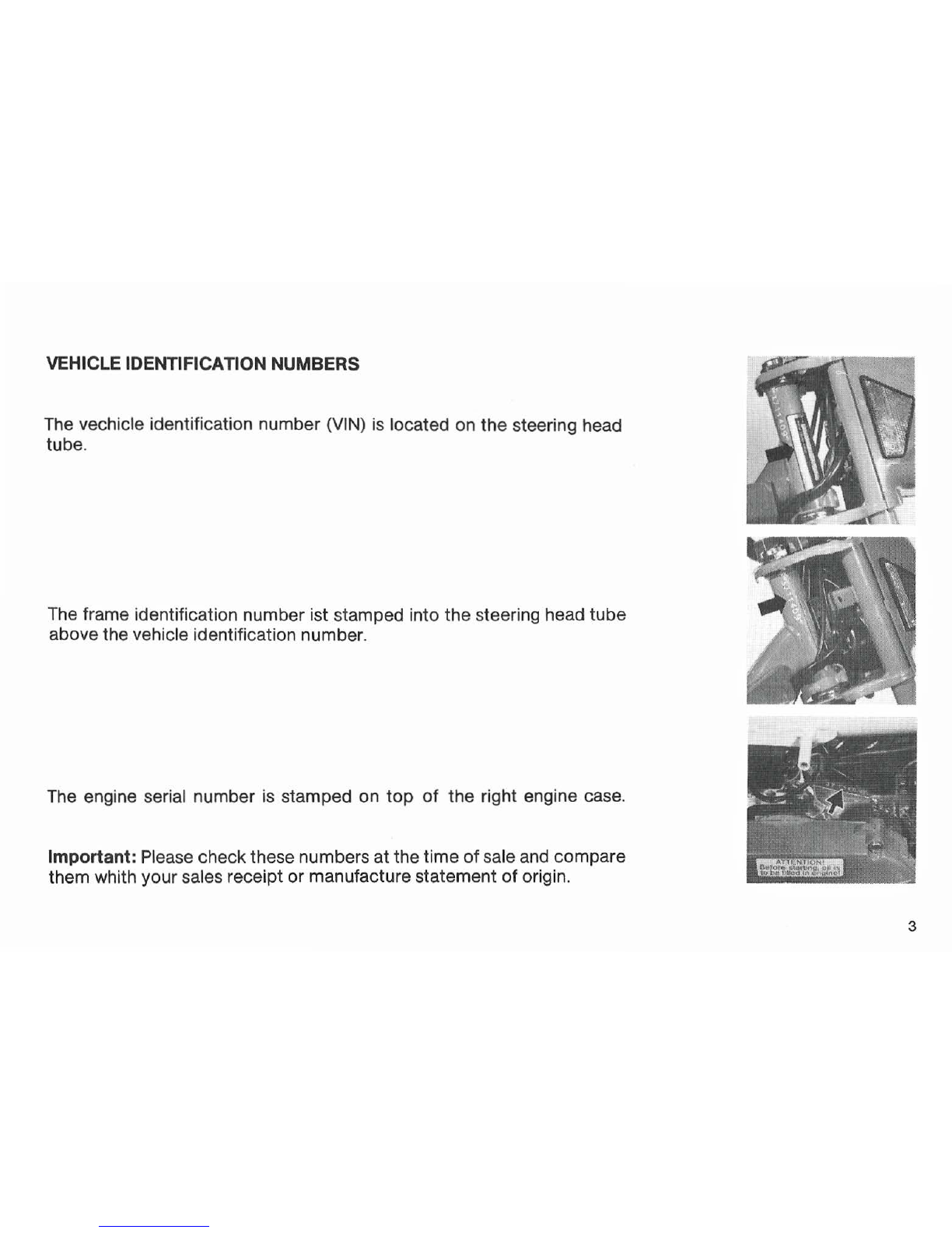
VEHICLE IDENTIFICATION NUMBERS
The vechicle identification number
(VIN)
is
located on the steering head
tube.
The frame identification number ist stamped into
the
steering head tube
above the vehicle identification number.
The
engine serial number
is
stamped on
top
of
the right engine case.
Important: Please checkthese numbers
at
the time
of
sale and compare
them whith your sales receipt
or
manufacture statement
of
origin.
3
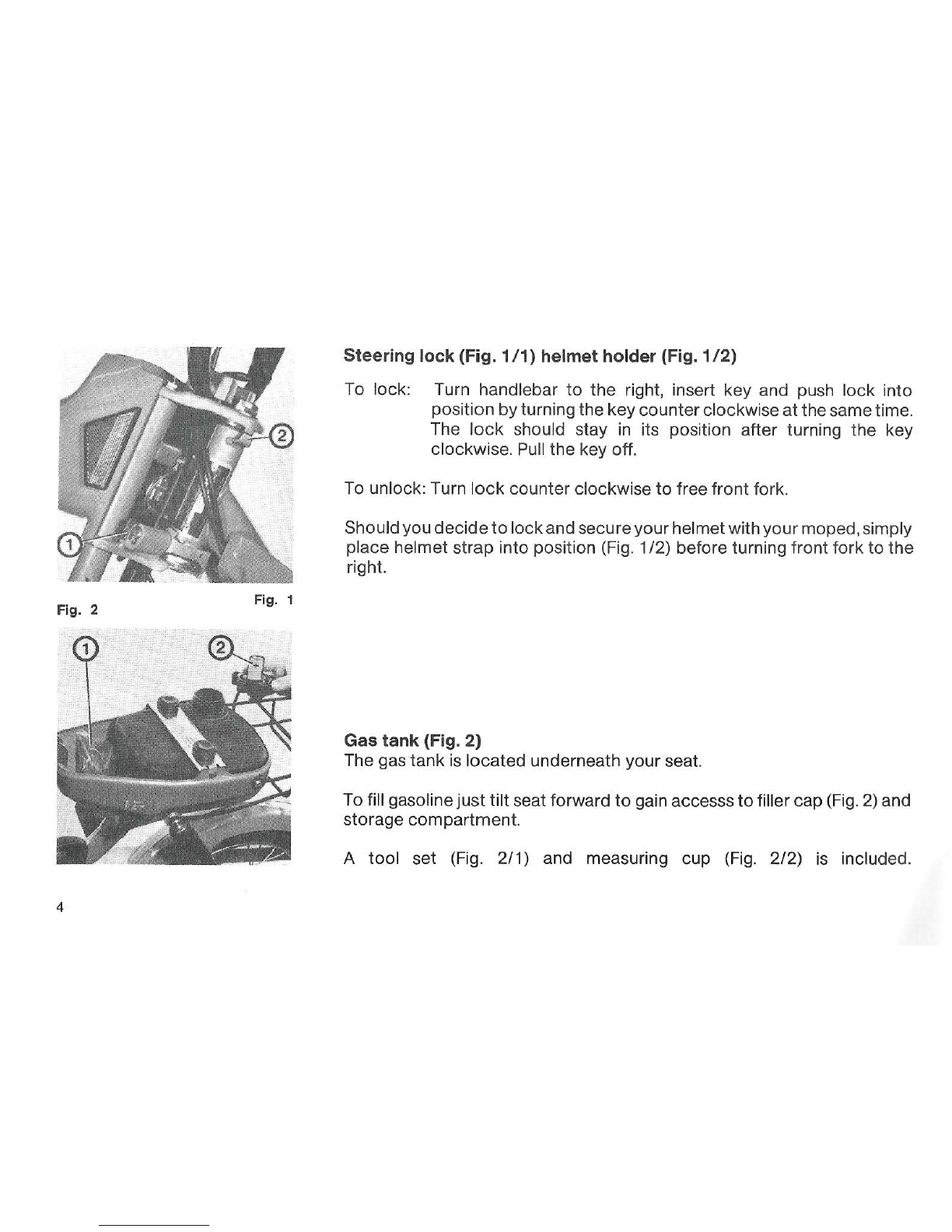
Fig. 2 Fig. 1
4
Steering lock (Fig. 1
/1)
helmet holder (Fig. 1
/2)
To lock: Turn handlebar
to
the
right, insert key and push lock into
position
by
turning the keycounterclockwiseatthesametime.
The
lock
should stay in its position after turning
the
key
clockwise.
Pull
the
key off.
To unlock: Turn
lock
counter clockwise
to
free
front
fork.
Shouldyou decide
to
lockandsecureyourhelmetwithyourmoped,simply
place helmet strap into position (Fig. 1/2) before turning front
fork
to
the
right.
Gas tank (Fig. 2)
The gas tank
is
located underneath your seat.
To fill gasolinejust
tilt
seat forward
to
gain accesss
to
filler cap (Fig.
2)
and
storage compartment.
A
tool
set (Fig. 2/1) and measuring
cup
(Fig. 2/2) is included.

Fuel Valve (Fig. 3)
The fuel valve
is
positioned onthe
I.
h.
side
of
your seat bench.
Position 1 = closed
Position 2 = open
Po
sition 3 = reserve
Carburetor
(fig
.
4)
Ch
oke
(Fig. 4/1). Push down
to
ac
tuate it. The
choke
will be released au-
tomatically (see riding instructions).
Primer (Fig.4/2).The primer button has
to
beheld down in order
to
flood
the carburetor.
St
op
priming
as
soon
as
gas drips from carburetor.
Fig. 3 Fig. 4
5
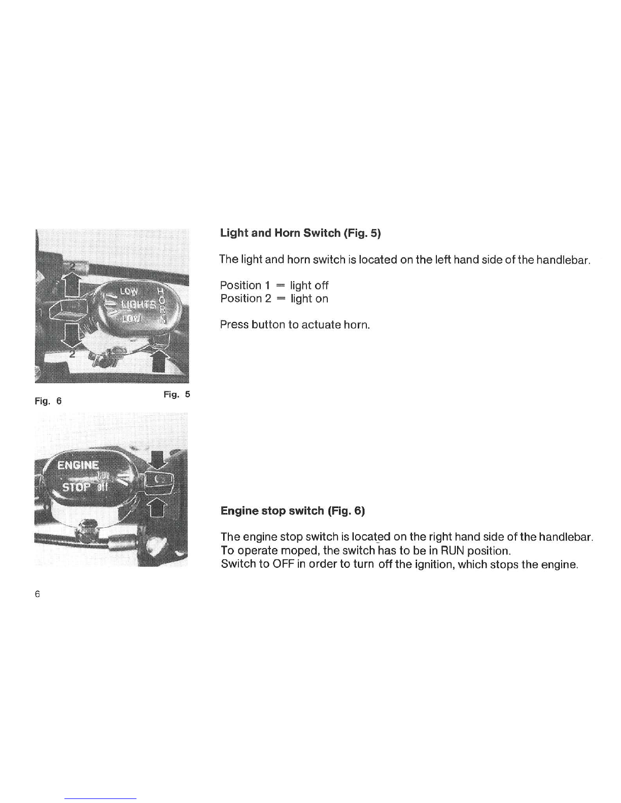
Fig. 6 Fig. 5
6
Light and Horn Switch (Fig.
5)
The light and horn switch is located on
the
left hand side
of
the handlebar.
Position 1 = light
off
Position 2 = light on
Press button
to
actuate horn.
Engine stop switch (Fig.
6)
The engine stopswitch is
locat_ed
on the right hand side
of
thehandlebar.
To operate moped, the switch has
to
be
in
RUN
position.
Switch
to
OFF
in
order
to
turn
off
the
ignition, which stops the engine.
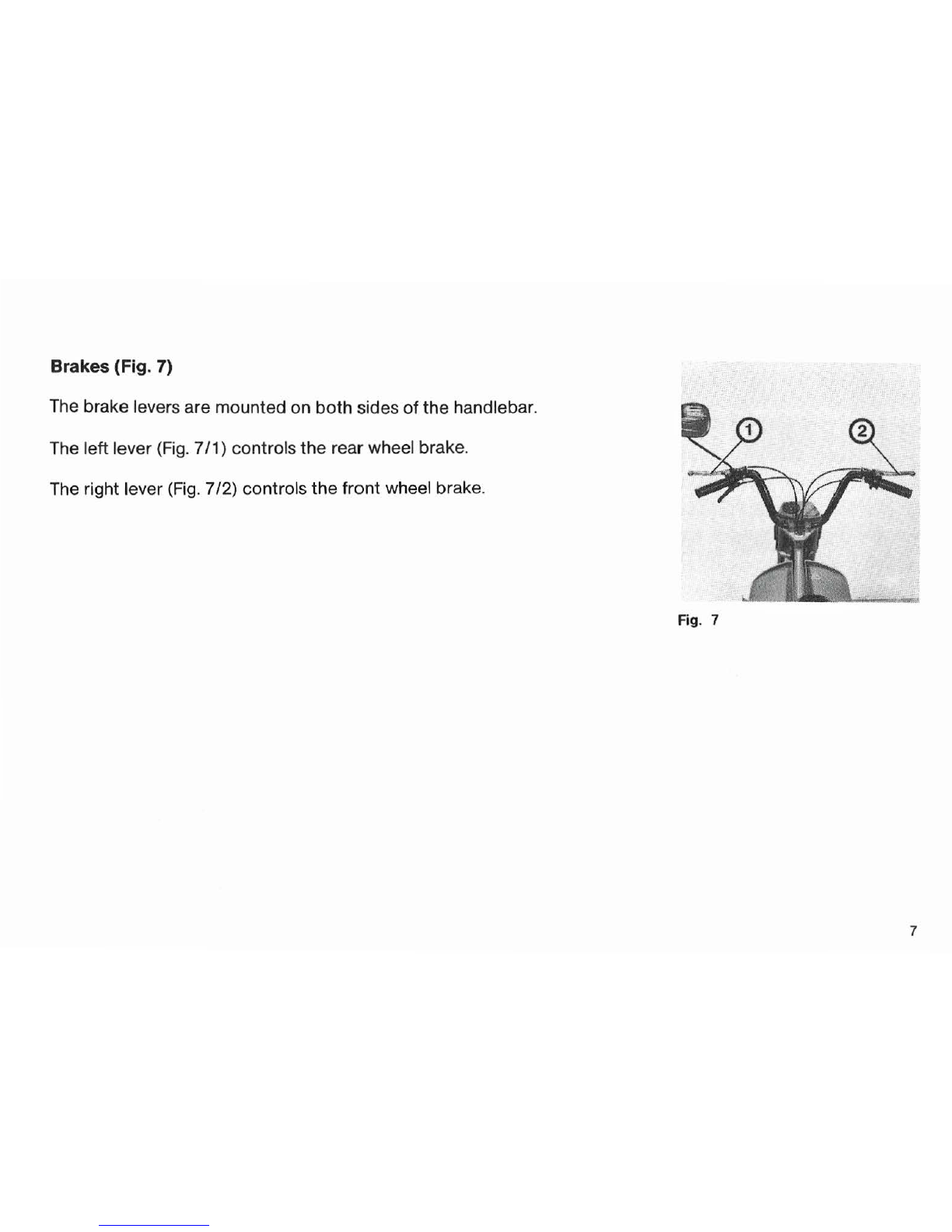
Brakes (Fig.
7)
The brake levers are mounted on both sides
of
the
handlebar.
The leftlever (Fig. 7/1) controls
the
rear wheel brake.
The right lever (Fig. 7/2) controls
the
front wheel brake.
Fig. 7
7
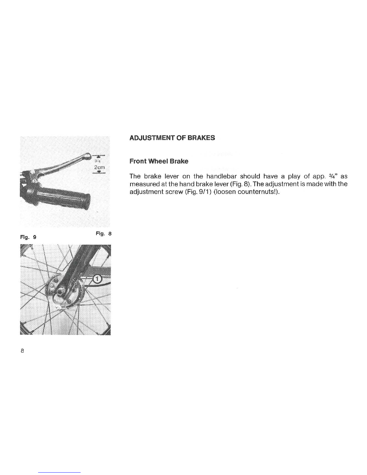
Fig. 9 Fig. 8
8
ADJUSTMENT
OF
BRAKES
Front Wheel Brake
The brake lever on
the
handlebar should have a play
of
app. 3/4" as
measured at
the
hand brake lever(Fig. 8). Theadjustmentis madewith
the
adjustment screw (Fig.
9/1)
(loosen counternuts!).

Rear Wheel Brake
The brake lever on
the
handlebar should have a play
of
app. 3
/4"
(see
Fig. 1
0).
Th
e adjustment is ra
de
with the ad
ju
stme
nt
screw (Fig. 11/1)
Fig.
10
Fig. 11
9
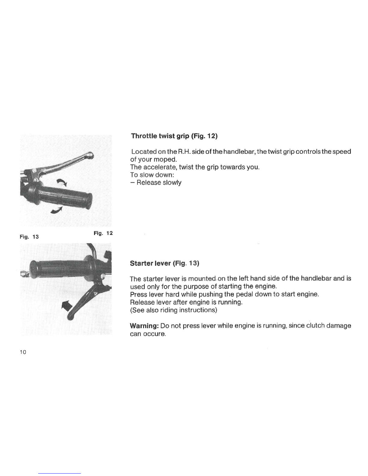
Fig.
13
Fig.
12
10
Throttle twist grip (Fig.
12)
Locatedon
the
R
.H.
side
of
the
handlebar,
the
twistgrip
co
ntrols
the
speed
of
your
moped.
The accelerate,
twist
the
grip
towards
you.
To
slow
down:
-Release slowly
Starterlever (Fig. 13)
The starter lever is
mounte
-d-on
the
lefthand side
of
the
handlebar and is
used only
for
the
purpose
of
starting
the
engine.
Press lever hard while pushing
the
pedal down
to
start engine.
Release leverafter engine is running.
(See also riding instructions)
Warning: Do
not
press leverwhile engine is running, since clutch damage
can occure.
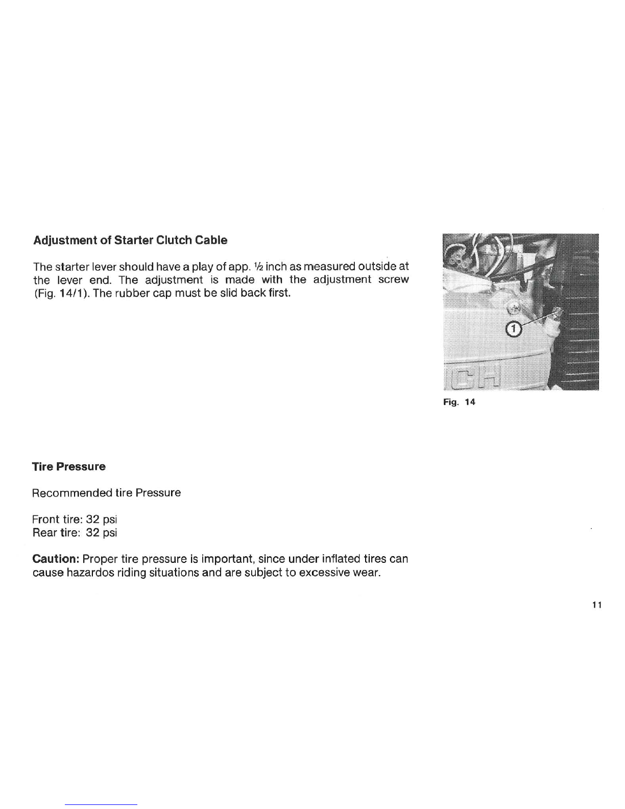
Adjustment
of
Starter
Clutch
Cable
The starter lever should have a play
of
app. 1
12
inch as measured outside at
the lever end. The adjustment is made with the adjustment screw
(Fig.
14/1
).
The rubber cap must
be
slid backfirst.
Tire Pressure
Recommended tire Pressure
Front tire:
32
psi
Rear tire:
32
psi
Caution: Proper
tire
pressure
is
important, since under inflated tires can
cause hazardos riding situations and are subject to excessive wear.
Fig.
14
11

!".......
~~::-·~-
~
~::---~,~
•.
·
'IEID
Gasoline/Oil Mixture
Fig.
16
Fig.
15
12
Filling up with
two
stroke mixture
All MAXI engines
must
be
run with a gas/oil mixture (regular gas).
There-
commended
mixing ratio is 50:1 when using s
pe
cial Maxi Mix
two
s
troke
mop
ed oiL
NOTE: DO
NOT
USE UNLEADED GASOLINE
PUCH MAXI MIX
50:
1 OIL MIXING TABLE
To 5 gallons gasoline add
12
fl.
oz.
(379
cc) oil
To 1 gallon gasoline add 2.4
fl.
oz.
(76
cc)
oil
To 1 quart gasoline add. 6 fl. oz.
(19
cc) oil
Use measuring
cup
for
pruperamounts
of
oil.
Ask
your
PUCH dealer
for
ma
xi
mix
oil.
NOTE: When using
other
brands
of
2
str
oke
oil,
do
not
exceed
the
50:1
mixing ratio.
WARNING
NEVER REFUEL WI
TH
THE ENGINE RUNNING!
DO NOTSMOKE OR ALLOW OPEN FLAMES OR SPARKS
IN
THE AREA
WHERE YOUR MOPED
IS
REFUELED AND/OR WHERE GASOLINE IS
STORED! CHECKWITH LOCALAUTHORITIES ABOUTTHESTORAGE OF
GASOLINE. ,
Transmission
fluid
The oil level screw(Fig.
17
I1)serves alsoasthefillerplug and is l
ocated
on
the clutch cover.
The drain plug (Fig.
17
/2) is located on
the
lower engine case.
To
fill oil: The
moped
must
be
in a level position when oil is filled
(off
kick
-
stand).
Use automatictransmission fluid
type
,F,
only.
The quantity
of
oil is 6
s;4
fl.
oz
.(200
cc)
or
fill untiloillevels
off
at
the
bottom
of
the
thread
of
filler plug. Fig.
17
13
c
Fig.
18a
Fig.
18
14
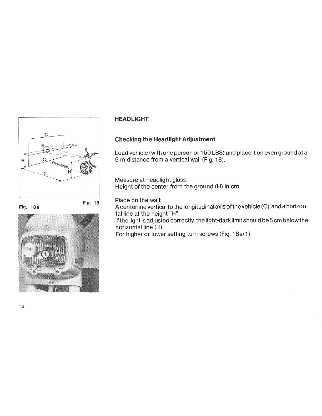
HEADLIGHT
Checking
the
Headlight Adjustment
Loadvehicle (with
one
person
or
150
LBS) andplaceit
on
even ground
at
a
5 m distancefrom a vertical wall (Fig. 18).
Measure
at
headlight glass:
Hei
ght
of
the
center
from
the
ground (H) in em.
Place on
the
wall:
Acenterlinevertical
to
the
longitudinalaxis
of
the
vehicle(C),andahorizon-
ta
l line
at
the
height "H".
If
the
li
ghtisadjustedcorrectly,
the
light-darklimitshouldbe5 em
below
the
horizontal line (H).
For higher
or
lower setting turn screws (Fig. 18a/1
).
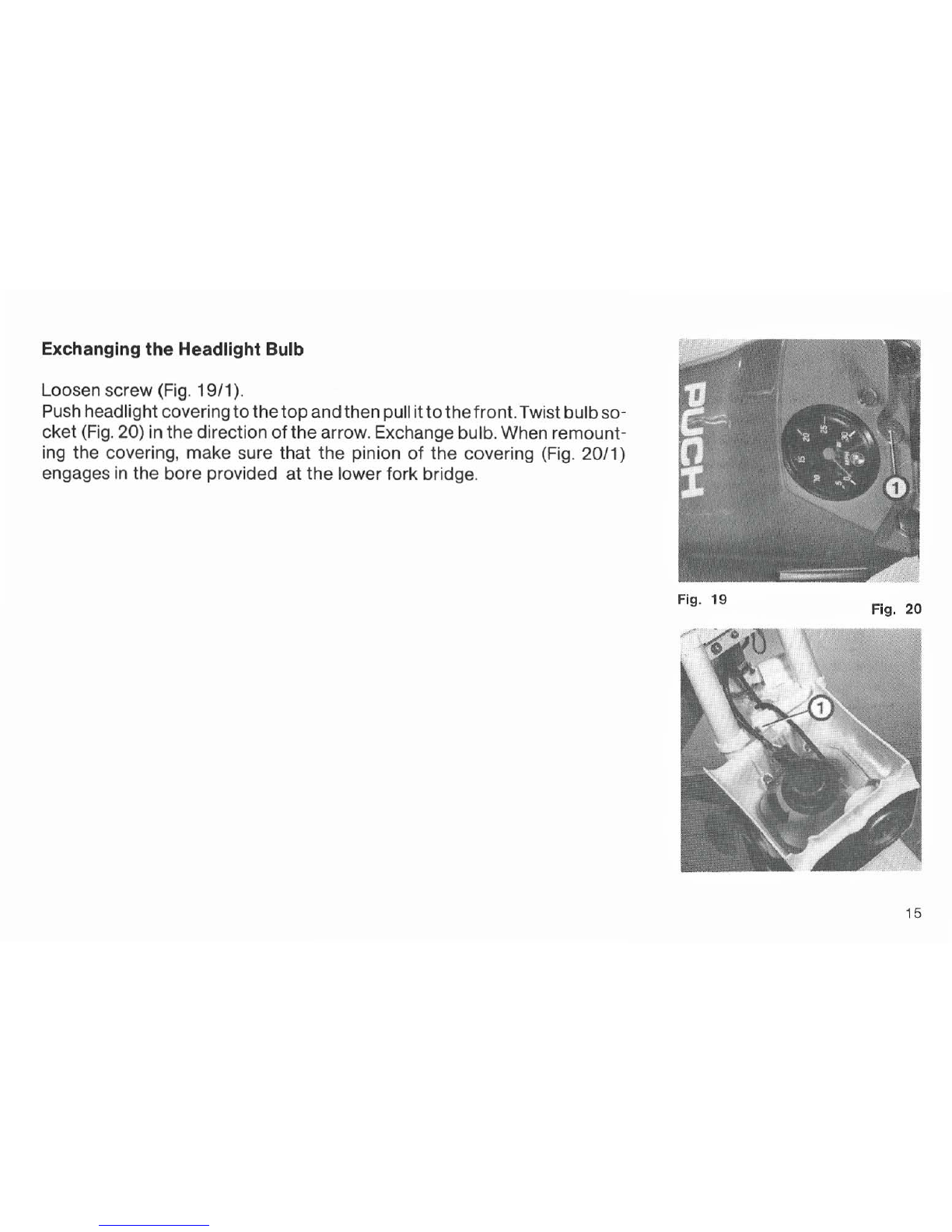
Exchanging
the
Headlight Bulb
Loosen screw (Fig. 19/1
).
Push headlightcovering
to
the
top
andthenpull it
to
thefront.Twistbulbso-
cket
(Fig. 20) inthedirection
of
the
arrow. Exchangebulb. When remount-
ing the covering, make sure that
the
pinion
of
the covering (Fig. 20/1)
engages
in
the bore provided
at
the
lowerfork bridge.
Fig.
19
Fig.
20
15
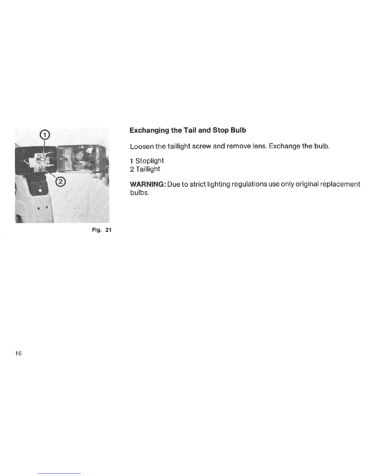
Fig. 21
16
Exchanging
the
Tail
and
Stop
Bulb
Loosen
the
taillight screw and remove lens. Exchange
the
bulb.
1 Stoplight
2 Taillight
WARNING: Due
to
strictlighting regulations use onlyoriginal replacement
bulbs.

RIDING INSTRUCTIONS
Starting
the
Moped
1. Prop the moped
on
its stand.
2.
Unlock fork.
3. Turn fuel valve
to
the ON position.
4. Be sure that the engine stop is in the
RUN
position.
5.
If
engineiscold,depressthe
choke
anddepresstheprimerbuttononthe
carburetor until fuel drips from carburetor.
6. Keep both hands on the handlebar with the weight
of
the moped cen-
teredonthefrontwheel.Applythefrontbrakeandfullydepressthestart-
ing
Lever
located on the left side
of
the
handlebar. Position
the
pedal
approx. parallel
to
the chain guard.
While holding
the
starter lever, push the pedal
to
start engine.
CAUTION: Aftercompleting step 5 and 6 donot open thethrottlecontrol,
asthis will deactivatethe choke.Afterthe engine has startedand warmed
up, open throttle gently
to
the full position briefly. This will disengage
choke. Avoid racing engine.
7. Alternate starting method:
Themoped mayalsobestarted
by
pedallingasabicycle.When momen-
tum
has been gained, pull the start lever and gently open the throttle.
Release the start leverafter
the
engine starts.
17

Fig.
23
Fig.
22
18
RIDING
1.
It
issuggested
to
wearbright clothing,utilizeeye protection,and proper
shoes
or
boots when riding your moped.
2.
Wearing ahelmetisrecommendedeventhoughoptional
in
manystates.
See your local
PUCH
DEALER
or
check with local law enforcement
agencies forstate law requirements.
3.
Be sure
to
switch on headlight at lowvisibility and/orwhere required
by
law.
4.
Themopedisdesigned
to
carryONEperson. Do
not
carryapassenger
or
very heavy cargo. Approved
PUCH
saddle bags and baskets are
availaple through your dealer.
5.
Obey all traffic regulations. Use hand signals when turning
or
changing
lanes. Please respect property
of
others and ride carefully. Keep your
feeton
the
pedalsatall times. Keepthepedals level, especiallyonturns.
6.
After reaching maximum speed, reduce the throttle opening
to
3/4.
While a reduction in speed will hardly be noticeable, fuel consumption
however will
be
considerably reduced.
7.
Closed throttle wi
ll
slow down moped when riding downhill.
8.
To ensure engine lubrication on long downhill rid
es,
open throttle
occasionally.

General Maintenance
Shouldyou feel able
to
perform small maintenance
work
on your moped,
makesurethatall nutsand boltsare tight andall other
co
mponentsarein
good working condition.
A service manual is available through
your
PUCH
dealer.
Any maintenance
or
service work requiring special
tools
and mechanical
skills should
be
performed
by
your
local PUCH dealer.
NOTE: The use
of
non
PUCH
authorizedsparepartscancausemalfunction
and hazardous riding situations
for
you.
Removal
of
front wheel
Unscrew speedometer cable (Fig. 24/1
).
Remove brake cable assembly
(Fig. 25/1), ifnecessary,loosensetscrew(Fig. 25/3).Loosenaxlenuts(Figs.
24/2
and 25/2). Remove wheel.
Fig.
24
Fig.
25
19
Other manuals for Mini maxi
1
Table of contents
Other Puch Scooter manuals


