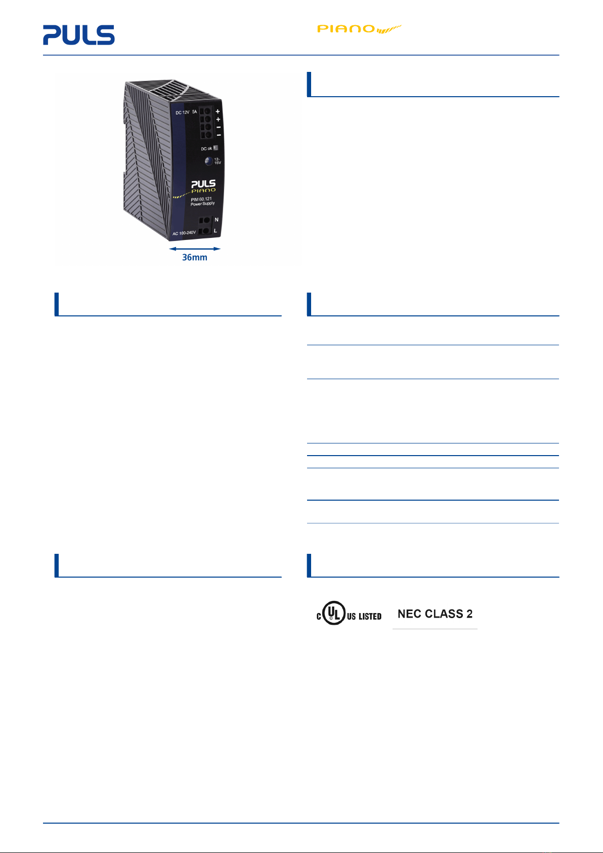
Puls PIM60.121 User manual

PIM60.121
Feb. 2022 / Rev. 2.0 DS-PIM60.121-EN www.pulsp wer.c m 1 / 17
All parameters are specified at 24V, 5A, 230Vac, 25°C ambient and after a 5 minutes run-in time unless therwise n ted.
POWER SUPPLY 1AC 12V 60W
•AC 100-240V Wide-range input
•NEC CLASS 2 c mpliant
•C st ptimized with ut c mpr mising quality r
reliability
•N PE c nnecti n required
•Width nly 36mm
•Efficiency up t 90.7%
•L w n -l ad p wer l sses
•Full p wer between -10°C and +60°C
•Push-in terminals
•3 Year warranty
PRODUCT DESCRIPTION SHORT-FORM DATA
The PIM60.121 is a DIN rail m untable single-phase-
input p wer supply, which pr vides a fl ating,
stabilized and galvanically separated SELV/PELV/ES1
utput v ltage. The utput fulfils the requirements
f r a limited p wer s urce acc rding t NEC CLASS 2.
The device is equipped with push-in terminals, which
are ptimized f r aut mated wiring.
The mechanically r bust h using is made f a high-
grade, reinf rced m lded material, which permits
surr unding temperatures up t +70°C.
The unit is designed as “Class f Pr tecti n” II unit and
fulfills the safety and EMC requirements with ut an
input PE c nnecti n. This saves wiring c sts.
The PIANO family is a c mpact industrial grade DIN rail
p wer supply series that f cuses n the essential
features needed in t day’s industrial applicati ns. The
excellent c st/perf rmance rati d es n t c mpr mise
quality r reliability.
Output v ltage DC 12V N minal
Adjustment range 12-15V Fact ry setting 12V
Output current 5-4A Bel w +60°C ambient
3.8-3A At +70°C ambient
Derate between +60°C and +70°C
Input v ltage AC AC 100-240V ± 10%
Mains frequency 50-60Hz ±6%
Input current AC 1 / 0.6A At 120 / 230Vac
P wer fact r 0.55 / 0.47 At 120 / 230Vac
Input inrush
current
15 / 36Apeak At 120 / 230Vac, +40°C,
c ld start
Efficiency 90.2 / 90.7% At 120 / 230Vac
P wer l sses 6.5 / 6.2W At 120 / 230Vac
H ld-up time 23 / 107ms At 120 / 230Vac
Temperature
range
-10°C t +70°C
Size (w x h x d) 36x90x91mm With ut DIN rail
Weight 225g / 0.5lb
ORDER NUMBERS MAIN APPROVALS
Description: P wer supply PIM60.121-xx
Order Number:
PIM60.121
F r details and the c mplete appr val list, see chapter 18.
Ind. C nt. Eq.

PIM60.121
Feb. 2022 / Rev. 2.0 DS-PIM60.121-EN www.pulsp wer.c m 2 / 17
All parameters are specified at 24V, 5A, 230Vac, 25°C ambient and after a 5 minutes run-in time unless therwise n ted.
Index
1 Intended Use....................................................... 3
2 Installati n Instructi ns...................................... 3
3 AC-Input.............................................................. 4
4 DC-Input.............................................................. 5
5 Input Inrush Current.......................................... 5
6 Output................................................................. 6
7 H ld-up Time...................................................... 7
8 Efficiency and P wer L sses.............................. 8
9 Lifetime Expectancy........................................... 9
10 MTBF.................................................................... 9
11 Functi nal Diagram............................................ 10
12 Terminals And Wiring........................................ 10
13 Fr nt Side And User Elements........................... 11
14 EMC..................................................................... 12
15 Envir nment....................................................... 13
16 Safety and Pr tecti n Features......................... 14
17 Dielectric Strength.............................................. 14
18 Appr ved, Fulfilled r Tested Standards........... 15
19 Regulat ry Pr duct C mpliance........................ 15
20 Physical Dimensi ns And Weight...................... 16
21 Applicati n N tes............................................... 17
21.1 Charging f Batteries.............................. 17
21.2 Series Operati n...................................... 17
21.3 Parallel Use t Increase Output P wer... 17
21.4 Parallel Use f r 1+1 Redundancy........... 17
21.5 Tw Phase Operati n............................. 17
21.6 Use in a Tightly Sealed Encl sure........... 17
The inf rmati n given in this d cument is c rrect t the best f ur kn wledge and experience at the time f publicati n.
If n t expressly agreed therwise, this inf rmati n d es n t represent a warranty in the legal sense f the w rd. As the
state f ur kn wledge and experience is c nstantly changing, the inf rmati n in this data sheet is subject t revisi n. We
theref re kindly ask y u t always use the latest issue f this d cument (available under www.pulsp wer.c m).
N part f this d cument may be repr duced r utilized in any f rm with ut ur pri r permissi n in writing.
Packaging and packaging aids can and sh uld always be recycled. The pr duct itself may n t be disp sed f as d mestic
refuse.
TERMINOLOGY AND ABBREVIATIONS
PE and Symbo PE is the abbreviati n f r Pr tective Earth and has the same meaning as the symb l .
Earth, Ground This d cument uses the term “earth” which is the same as the U.S. term “gr und”.
t.b.d. T be defined, value r descripti n will f ll w later.
AC 230V A figure displayed with the AC r DC bef re the value represents a n minal v ltage with
standard t lerances (usually ±15%) included.
E.g.: DC 12V describes a 12V battery disregarding whether it is full (13.7V) r flat (10V)
230Vac A figure with the unit (Vac) at the end is a m mentary figure with ut any additi nal
t lerances included.
50Hz vs. 60Hz As l ng as n t therwise stated, AC 100V and AC 230V parameters are valid at 50Hz mains
frequency. AC 120V parameters are valid f r 60Hz mains frequency.
may A key w rd indicating flexibility f ch ice with n implied preference.
sha A key w rd indicating a mandat ry requirement.
shou d A key w rd indicating flexibility f ch ice with a str ngly preferred implementati n.

PIM60.121
Feb. 2022 / Rev. 2.0 DS-PIM60.121-EN www.pulsp wer.c m 3 / 17
All parameters are specified at 24V, 5A, 230Vac, 25°C ambient and after a 5 minutes run-in time unless therwise n ted.
1. Intended Use
This device is designed f r installati n in an encl sure and is intended f r c mmercial use, such as in industrial c ntr l,
pr cess c ntr l, m nit ring, measurement, Audi /Vide , inf rmati n r c mmunicati n equipment r the like.
D n t use this device in equipment, where malfuncti ning may cause severe pers nal injury r threaten human life with ut
additi nal appr priate safety devices, that are suited f r the end-applicati n. If this device is used in a manner utside f
its specificati n, the pr tecti n pr vided by the device may be impaired.
D n t use this device n AC 100V mains with m re than 3.6A l ad when the applicati n is sensitive t sh rt utput v ltage
dips during mains interrupti ns even with a length sh rter than 20ms.
2. Installati n Instructi ns
DANGER Risk of e ectrica shock, fire, persona injury or death.
– Turn p wer ff bef re w rking n the device. Pr tect against inadvertent re-p wering.
– D n t pen, m dify r repair the device.
– Use cauti n t prevent any f reign bjects fr m entering the h using.
– D n t use in wet l cati ns r in areas where m isture r c ndensati n can be expected.
– D n t t uch during p wer- n, and immediately after p wer- ff. H t surfaces may cause burns.
Obey the fo owing insta ation instructions:
This device may nly be installed and put int perati n by qualified pers nnel. This device d es n t c ntain serviceable
parts. The tripping f an internal fuse is caused by an internal defect. If damage r malfuncti n sh uld ccur during
installati n r perati n, immediately turn p wer ff and send unit t the fact ry f r inspecti n.
Install device in an encl sure pr viding pr tecti n against electrical, mechanical and fire hazards. Install the device nt a
DIN rail acc rding t EN 60715 with the input terminals n the b tt m f the device.
Make sure that the wiring is c rrect by f ll wing all l cal and nati nal c des. Use appr priate c pper cables that are
designed f r a minimum perating temperature f +60°C f r ambient temperatures up t +45°C, +75°C f r ambient
temperatures up t +60°C and +90°C f r ambient temperatures up t +70°C. Ensure that all strands f a stranded wire
enter the terminal c nnecti n.
The device is designed f r p lluti n degree 2 areas in c ntr lled envir nments. N c ndensati n r fr st is all wed. The
encl sure f the device pr vides a degree f pr tecti n f IP20. The encl sure d es n t pr vide pr tecti n against spilled
liquids.
The device is designed f r verv ltage categ ry II z nes. Bel w 2000m altitude the device is tested f r impulse withstand
v ltages up t 4kV, which c rresp nds t OVC III acc rding t IEC 60664-1.
The device is designed as “Class f Pr tecti n” II equipment acc rding t IEC 61140.
The device is suitable t be supplied fr m TN, TT r IT mains netw rks. The c ntinu us v ltage between the input terminal
and the PE p tential must n t exceed 300Vac. A disc nnecting means shall be pr vided f r the input f the device.
The device is designed f r c nvecti n c ling and d es n t require an external fan. D n t bstruct airfl w and d n t
c ver ventilati n grid!
The device is designed f r altitudes up t 5000m (16 400ft). Ab ve 2000m (6560ft) a reducti n in utput current is required.
Keep the f ll wing minimum installati n clearances: 40mm n t p, 20mm n the b tt m, 0mm left and right side. Increase
the 0mm t 15mm in case the adjacent device is a heat s urce.
The device is designed, tested and appr ved f r branch circuits up t 20A with ut additi nal pr tecti n device. If an
external fuse is utilized, d n t use circuit breakers smaller than 6A B- r 4A C-Characteristic t av id a nuisance tripping
f the circuit breaker.
The maximum surr unding air temperature is +70°C (158°F). The perati nal temperature is the same as the ambient r
surr unding air temperature and is defined 2cm bel w the device. The device is designed t perate in areas between 5%
and 95% relative humidity.

PIM60.121
Feb. 2022 / Rev. 2.0 DS-PIM60.121-EN www.pulsp wer.c m 4 / 17
All parameters are specified at 24V, 5A, 230Vac, 25°C ambient and after a 5 minutes run-in time unless therwise n ted.
3. AC-Input
The device is suitable t be supplied fr m TN, TT r IT mains netw rks.
AC input n m. AC 100-240V
AC input range 90-264Vac C ntinu us perati n
264-300Vac F r maximum 500ms
All wed v ltage L r N t
earth
max. 300Vac C ntinu us, acc rding t IEC 60664-1
Input frequency n m. 50-60Hz ±6%
Turn- n v ltage typ. 75Vac Steady-state value, see Fig. 3-1
Shut-d wn v ltage typ. 54Vac Steady-state value, see Fig. 3-1
External input pr tecti n See rec mmendati ns in chapter 2.
AC 100V AC 120V AC 230V
Input current typ. 1.15A 1A 0.6A At 12V, 5A, see Fig. 3-1
P wer fact r typ. 0.58 0.55 0.47 At 12V, 5A, see Fig. 3-4
Start-up delay typ. 50ms 50ms 60ms See Fig. 3-2
typ. 18ms 18ms 18ms At 12V, 5A c nstant current l ad,
0mF l ad capacitance, see Fig. 3-2
Rise time
typ. 30ms 30ms 30ms At 12V, 5A c nstant current l ad,
2mF l ad capacitance, see Fig. 3-2
Turn- n versh t max. 100mV 100mV 100mV See Fig. 3-2
Fig. 3-1: Input v ltage range Fig. 3-2: Turn- n behavi r, definiti ns
Fig. 3-3: Input current vs. utput
l ad at 12V utput v ltage
Fig. 3-4: P wer fact r vs. utput
l ad at 12V utput v ltage

PIM60.121
Feb. 2022 / Rev. 2.0 DS-PIM60.121-EN www.pulsp wer.c m 5 / 17
All parameters are specified at 24V, 5A, 230Vac, 25°C ambient and after a 5 minutes run-in time unless therwise n ted.
4. DC-Input
D n t perate this device with DC-input v ltage.
5. Input Inrush Current
A NTC limits the input inrush current after turn- n f the input v ltage. The inrush current is input v ltage and ambient
temperature dependent. The utput l ad has n impact n the inrush current value.
The charging current int EMI suppressi n capacit rs is disregarded in the first micr sec nds after switch- n.
AC 100V AC 120V AC 230V
typ. 12A 15A 36A At 40°C, ambient, c ld startInrush current Ipeak
typ. 10A 12A 30A At 25°C, ambient, c ld start
max. 15A 18A 44A At 40°C, ambient, c ld start
max. 12A 15A 36A At 25°C, ambient, c ld start
Inrush energy I2t max. 0.2A2s 0.3A2s 1.4A2s At 40°C, ambient, c ld start
Fig. 5-1: Typical turn- n behavi r
at 120Vac and 25°C ambient
Fig. 5-2: Z m int the first inrush peak
Fig. 5-3: Typical turn- n behavi r
at 230Vac and 25°C ambient
Fig. 5-4: Z m int the first inrush peak

PIM60.121
Feb. 2022 / Rev. 2.0 DS-PIM60.121-EN www.pulsp wer.c m 6 / 17
All parameters are specified at 24V, 5A, 230Vac, 25°C ambient and after a 5 minutes run-in time unless therwise n ted.
6. Output
The utput pr vides a SELV/PELV/ES1 rated v ltage, which is galvanically is lated fr m the input v ltage. The utput is
electr nically pr tected against n -l ad, verl ad and sh rt circuit. In case f a pr tecti n event, audible n ise may ccur.
The utput is designed t supply any kind f l ads, including inductive and capacitive l ads. Capacitive l ads sh uld n t
be larger than 2 200μF with 5A r 8 000μF with 2.5A additi nal current l ad.
At heavy verl ads (when utput v ltage falls bel w 8V), the device delivers c ntinu us utput current f r 20ms. After this,
the utput is switched ff f r appr x. 170ms bef re a new start attempt is aut matically perf rmed. This cycle is repeated
as l ng as the verl ad exists.
If the verl ad has been cleared, the device will perate n rmally.
Output v ltage n m. DC 12V
Adjustment range 12-15V Guaranteed value
max. 15.5V This is the maximum utput v ltage which can ccur at
the cl ckwise end p siti n f the p tenti meter due
t t lerances. It is n t a guaranteed value which can be
achieved.
Fact ry settings typ. 12V ±0,2%, at full l ad, c ld unit
Line regulati n max. 10mV Between 90 and 300Vac
L ad regulati n max. 100mV Between 0 and 5A, static value, see Fig. 6-1
Ripple and n ise v ltage max. 100mVpp Bandwidth 20Hz t 20MHz, 50Ohm
Output current n m. 5A At 12V and an ambient temperature bel w 60°C
n m. 3.8A At 12V and 70°C ambient temperature
n m. 4A At 15V and an ambient temperature bel w 60°C
n m. 3A At 15V and 70°C ambient temperature
Overl ad behavi ur C ntinu us current F r utput v ltage ab ve 8Vdc, see Fig. 6-1
Intermittent current F r utput v ltage bel w 8Vdc, see Fig. 6-2
max. 7A C ntinu us current, see Fig. 6-1Overl ad/
sh rt-circuit current typ. 9A Intermitted current peak value f r typ. 20ms
L ad impedance 150mOhm, see Fig. 6-2
Discharge current f utput capacit rs is n t included.
max. 3.2A Intermitted current average value (R.M.S.)
L ad impedance 150mOhm, see Fig. 6-2
Output capacitance typ. 2 200μF Included inside the device
Back-feeding l ads max. 16V The unit is resistant and d es n t sh w malfuncti ning
when a l ad feeds back v ltage t the device. It d es n t
matter whether the device is n r ff. The abs rbing
energy can be calculated acc rding t the built-in large
sized utput capacit r.
Fig. 6-1: Output v ltage vs. utput current, typ. Fig. 6-2: Intermittend current at sh rt circuit, typ.*)
*) with c ld devices the times are ab ut 15% l nger.

PIM60.121
Feb. 2022 / Rev. 2.0 DS-PIM60.121-EN www.pulsp wer.c m 7 / 17
All parameters are specified at 24V, 5A, 230Vac, 25°C ambient and after a 5 minutes run-in time unless therwise n ted.
7. H ld-up Time
The h ld-up time is the time during which a device’s utput v ltage remains within specificati n f ll wing the l ss f input
p wer. The h ld-up time is utput l ad dependent. At n l ad, the h ld-up time can be up t several sec nds. The green
DC-OK LED is als n during this time.
AC 100V AC 120V AC 230V
H ld-up time typ. 13ms 23ms 107ms At 12V, 5A
typ. 36ms 55ms 219ms At 12V, 2.5A
min. 10.5ms 18ms 85ms At 12V, 5A
min. 28.5ms 43ms 175ms At 12V, 2.5A
Fig. 7-1: H ld-up time vs. input v ltage Fig. 7-2: Shut-d wn behavi ur, definiti ns

PIM60.121
Feb. 2022 / Rev. 2.0 DS-PIM60.121-EN www.pulsp wer.c m 8 / 17
All parameters are specified at 24V, 5A, 230Vac, 25°C ambient and after a 5 minutes run-in time unless therwise n ted.
8. Efficiency and P wer L sses
AC 100V AC 120V AC 230V
Efficiency typ. 88.9% 90.2% 90.7% At 12V, 5A (full l ad)
Average efficiency typ. 88.9% 89.7% 89.6% 25% at 1.25A, 25% at 2.5A,
25% at 3.75A, 25% at 5A
P wer l sses typ. 0.2W 0.2W 0.3W At n l ad
typ. 3.6W 3.4W 3.4W At 12V, 2.5A (half l ad)
typ. 7.5W 6.5W 6.2W At 12V, 5A (full l ad)
The average efficiency is an assumpti n f r a typical applicati n where the device is l aded with 25% f the n minal
l ad f r 25% f the time, 50% f the n minal l ad f r an ther 25% f the time, 75% f the n minal l ad f r an ther
25% f the time and with 100% f the n minal l ad f r the rest f the time.
Fig. 8-1: Efficiency vs. utput current at 12V, typ. Fig. 8-2: L sses vs. utput current at 12V, typ.
Fig. 8-3: Efficiency vs. input v ltage at 12V, 5A, typ. Fig. 8-4: L sses vs. input v ltage at 12V, 5A, typ.

PIM60.121
Feb. 2022 / Rev. 2.0 DS-PIM60.121-EN www.pulsp wer.c m 9 / 17
All parameters are specified at 24V, 5A, 230Vac, 25°C ambient and after a 5 minutes run-in time unless therwise n ted.
9. Lifetime Expectancy
The Lifetime expectancy sh wn in the table indicates the minimum perating h urs (service life) and is determined by
the lifetime expectancy f the built-in electr lytic capacit rs. Lifetime expectancy is specified in perati nal h urs and is
calculated acc rding t the capacit r’s manufacturer specificati n.
P ease note: The manufacturer f the electr lytic capacit rs nly guarantees a maximum life f up t 15 years (131 400h).
Any number exceeding this value is a calculated the retical lifetime which can be used t c mpare devices.
AC 100V AC 120V AC 230V
Lifetime expectancy 89 000h 103 000h 119 000h At 12V, 5A and 40°C
241 000h 249 000h 256 000h At 12V, 2.5A and 40°C
252 000h 292 000h 335 000h At 12V, 5A and 25°C
680 000h 704 000h 724 000h At 12V, 2.5A and 25°C
10. MTBF
MTBF stands f r Mean Time Between Failure, which is calculated acc rding t statistical device failures, and indicates
reliability f a device. It is the statistical representati n f the likelih d f a unit t fail and d es n t necessarily represent
the life f a pr duct.
The MTBF figure is a statistical representati n f the likelih d f a device t fail. A MTBF figure f e.g. 1 000 000h means
that statistically ne unit will fail every 100 h urs if 10 000 units are installed in the field. H wever, it cann t be determined
if the failed unit has been running f r 50 000h r nly f r 100h.
F r these types f units the MTTF (Mean Time T Failure) value is the same value as the MTBF value.
AC 100V AC 120V AC 230V
MTBF SN 29500, IEC 61709 1 542 000h 1 649 000h 1 673 000h At 12V, 5A and 40°C
2 768 000h 2 911 000h 2 925 000h At 12V, 5A and 25°C
MTBF MIL HDBK 217F 695 000h 707 000h 685 000h At 12V, 5A and 40°C; Gr und Benign GB40
993 000h 1 008 000h 982 000h At 12V, 5A and 25°C; Gr und Benign GB25
189 000h 192 000h 197 000h At 12V, 5A and 40°C; Gr und Fixed GF40
246 000h 250 000h 258 000h At 12V, 5A and 25°C; Gr und Fixed GF25

PIM60.121
Feb. 2022 / Rev. 2.0 DS-PIM60.121-EN www.pulsp wer.c m 10 / 17
All parameters are specified at 24V, 5A, 230Vac, 25°C ambient and after a 5 minutes run-in time unless therwise n ted.
11. Functi nal Diagram
Fig. 11-1: Functi nal diagram
12. Terminals And Wiring
The terminals are IP20 Finger safe c nstructed and suitable f r field- and fact ry wiring.
A Termina s
Type Push-in terminals
S lid wire max. 2.5mm2
Stranded wire max. 2.5mm2
Stranded wire with ferrules max. 1.5mm2
American Wire Gauge AWG 24-12
Max. wire diameter (including ferrules) 2.3mm
Wire stripping length 10mm / 0.4inch
Screwdriver 3mm sl tted t pen the spring

PIM60.121
Feb. 2022 / Rev. 2.0 DS-PIM60.121-EN www.pulsp wer.c m 11 / 17
All parameters are specified at 24V, 5A, 230Vac, 25°C ambient and after a 5 minutes run-in time unless therwise n ted.
13. Fr nt Side And User Elements
A Input Termina s
NNeutral c nduct r input
LPhase (Line) input
B OutputTermina s
Dual terminals f r the negative and p sitive p le.
B th p les are internally c nnected.
+P sitive utput
- Negative (return) utput
C DC OK LED (green)
The LED is n, when the utput v ltage is ab ve 9V.
Fig. 13-1: Fr nt side
D Output vo tage adustment potentiometer

PIM60.121
Feb. 2022 / Rev. 2.0 DS-PIM60.121-EN www.pulsp wer.c m 12 / 17
All parameters are specified at 24V, 5A, 230Vac, 25°C ambient and after a 5 minutes run-in time unless therwise n ted.
14. EMC
The EMC behavi r f the device is designed f r applicati ns in industrial envir nment as well as in residential, c mmercial
and light industry envir nments.
The device c mplies with EN 61000-6-1, EN 61000-6-2, EN 61000-6-3, EN 61000-6-4, EN 61000-3-2 and EN 61000-3-3. The
device c mplies with FCC Part 15 rules. Operati n is subjected t f ll wing tw c nditi ns: (1) this device may n t cause
harmful interference, and (2) this device must accept any interference received, including interference that may cause
undesired perati n.
D n t use this device n AC 100V mains with m re than 3.6A l ad when the applicati n is sensitive t sh rt utput v ltage
dips during mains interrupti ns even with a length sh rter than 20ms.
EMC Immunity
Electr static discharge EN 61000-4-2 C ntact discharge 8kV Criteri n A
Air discharge 8kV Criteri n A
Electr magnetic RF field EN 61000-4-3 80MHz - 6GHz 10V/m Criteri n A
Fast transients (Burst) EN 61000-4-4 Input lines 4kV Criteri n A
Output lines 2kV Criteri n A
Surge v ltage n input EN 61000-4-5 L → N 2kV Criteri n A
N / L → Earthed utput 4kV Criteri n A
Surge v ltage n utput EN 61000-4-5 (+) → (−) 1kV Criteri n A
(+) → (−) Earthed 1kV Criteri n A
(−) → (+) Earthed 1kV Criteri n A
C nducted disturbance EN 61000-4-6 0.15 - 80MHz 10V Criteri n A
V ltage dips EN 61000-4-11 0% f 100Vac 0Vac, 20ms Criteri n A/C
40% f 100Vac 40Vac, 200ms Criteri n C
70% f 100Vac 70Vac, 500ms Criteri n A
0% f 120Vac 0Vac, 20ms Criteri n A
40% f 120Vac 48Vac, 200ms Criteri n C
70% f 120Vac 84Vac, 500ms Criteri n A
0% f 200Vac 0Vac, 20ms Criteri n A
40% f 200Vac 80Vac, 200ms Criteri n A
70% f 200Vac 140Vac, 500ms Criteri n A
V ltage interrupti ns EN 61000-4-11 0V 5000ms Criteri n C
P werful transients VDE 0160 Over entire l ad range 750V, 1.3ms Criteri n A
Performance criterions:
A: The device sh ws n rmal perati n behavi r within the defined limits.
B: The device perates c ntinu usly during and after the test. During the test min r temp rary impairments may
ccur, which will be c rrected by the device itself.
C: Temp rary l ss f functi n is p ssible. The device may shut-d wn and restarts by itself. N damage r hazards
f r the device will ccur.
A/C: Criteri n A f r utput current bel w 3.6A and criteri n C f r utput currents ab ve 3.6A.
EMC Emission
C nducted emissi n input lines EN 55011, EN 55032, FCC Part 15, CISPR 11,
CISPR32
Class B
C nducted emissi n utput lines IEC/CISPR 16-1-2, IEC/CISPR 16-2-1 Limits f r l cal DC p wer netw rks
fulfilled.
Radiated emissi n EN 55011, EN 55032, CISPR 11, CISPR 32 Class B
Harm nic input current EN 61000-3-2 Fulfilled (Class A)
V ltage fluctuati ns, flicker EN 61000-3-3 Fulfilled, tested with n n pulsing
c nstant current l ads.
Switching Frequencies
Main c nverter 1kHz t 130kHz Input v ltage and utput l ad
dependent

PIM60.121
Feb. 2022 / Rev. 2.0 DS-PIM60.121-EN www.pulsp wer.c m 13 / 17
All parameters are specified at 24V, 5A, 230Vac, 25°C ambient and after a 5 minutes run-in time unless therwise n ted.
15. Envir nment
Operati nal temperature -10°C t +70°C (14°F t 158°F) The perati nal temperature is the ambient r
surr unding temperature and is defined as the
air temperature 2cm bel w the device.
St rage temperature -40°C t +85°C (-40°F t 185°F) F r st rage and transp rtati n
Output derating 0.12A/°C Between +60°C and +70°C (140°F t 158°F)
0.3A/1000m r 5°C/1000m F r altitudes >2000m (6560ft), see Fig. 15-2
The derating is n t hardware c ntr lled. The user has t take this int c nsiderati n t
stay bel w the derated current limits in rder n t t verl ad the unit.
Humidity 5 t 95% r.h. Acc rding t IEC 60068-2-30
N c ndensati n all wed.
Atm spheric pressure 110-54kPa See Fig. 15-2 f r details
Altitude Up t 5000m (16 400ft) See Fig. 15-2 f r details
Over-v ltage categ ry II Acc rding t IEC 60664-1, f r altitudes
<5000m
Impulse withstand v ltage 4kV (acc rding t ver-v ltage
categ ry III)
Input t PE
Acc rding t IEC 60664-1, f r altitudes
<2000m
Degree f p lluti n 2 Acc rding t IEC 60664-1, n n c nductive
Vibrati n sinus idal 2-17.8Hz: ±1.6mm
17.8-500Hz: 2g
2 h urs / axis
Acc rding t IEC 60068-2-6
Sh ck 30g 6ms, 20g 11ms
3 bumps / directi n, 18 bumps in t tal
Acc rding t IEC 60068-2-27
Sh ck and vibrati n is tested in c mbinati n with DIN rails acc rding t EN 60715 with
a height f 15mm and a thickness f 1.3mm.
Fig. 15-1: Output p wer vs. ambient temp. Fig. 15-2: Output p wer vs. altitude

PIM60.121
Feb. 2022 / Rev. 2.0 DS-PIM60.121-EN www.pulsp wer.c m 14 / 17
All parameters are specified at 24V, 5A, 230Vac, 25°C ambient and after a 5 minutes run-in time unless therwise n ted.
16. Safety and Pr tecti n Features
Is lati n resistance >500MOhm At delivered c nditi n between input and utput,
measured with 500Vdc
Output ver-v ltage pr tecti n typ. 16.5Vdc
max. 17Vdc
In case f an internal defect, a redundant circuit limits the maximum utput
v ltage t 17V. The utput shuts d wn. T attempt a restart, turn the input
p wer ff f r at least 90s.
Class f pr tecti n II Acc rding t IEC 61140
Degree f pr tecti n IP20 Acc rding t EN/IEC 60529
Over-temperature pr tecti n N t Included
Input transient pr tecti n MOV (Metal Oxide Varist r) F r pr tecti n values see chapter 14 (EMC).
Internal input fuse Included N t user replaceable sl w-bl w high-braking
capacity fuse
typ. 40μA / 80μA At 100Vac, 50Hz, TN-, TT-mains / IT-mains
typ. 60μA / 120μA At 120Vac, 60Hz, TN-, TT-mains / IT-mains
typ. 100μA / 200μA At 230Vac, 50Hz, TN-, TT-mains / IT-mains
max. 60μA / 100μA At 110Vac, 50Hz, TN-, TT-mains / IT-mains
max. 80μA / 150μA At 132Vac, 60Hz, TN-, TT-mains / IT-mains
T uch current (leakage current)
max. 140μA / 260μA At 264Vac, 50Hz, TN-, TT-mains / IT-mains
17. Dielectric Strength
The utput v ltage is fl ating and has n hmic c nnecti n t the gr und.
The utput is insulated t the input by a d uble r reinf rced insulati n.
Type and r utine tests are c nducted by the manufacturer. Field tests may be c nducted in the field using the appr priate
test equipment which applies the v ltage with a sl w ramp (2s up and 2s d wn). C nnect all phase-terminals t gether
as well as all utput p les bef re c nducting the test. When testing, set the cut- ff current settings t the value in the
table bel w.
It is rec mmended that either the (+) p le r the (–) p le shall be c nnected t the pr tective earth system. This helps t
av id situati ns in which a l ad starts unexpectedly r cann t be switched ff when unn ticed earth faults ccur.
Fig. 17-1: Dielectric strength
A
Type test 60s 3000Vac
Fact ry test 5s 2500Vac
Field test 5s 2000Vac
Field test cut- ff current
settings
>5mA

PIM60.121
Feb. 2022 / Rev. 2.0 DS-PIM60.121-EN www.pulsp wer.c m 15 / 17
All parameters are specified at 24V, 5A, 230Vac, 25°C ambient and after a 5 minutes run-in time unless therwise n ted.
18. Appr ved, Fulfilled r Tested Standards
IEC 61010 CB Scheme Certificate
IEC 61010-2-201 - Electrical Equipment f r Measurement, C ntr l and
Lab rat ry Use - Particular requirements f r c ntr l equipment
IEC 62368 CB Scheme Certificate
IEC 62368-1 - Audi /vide , inf rmati n and c mmunicati n
techn l gy equipment - Safety requirements
Output safety level: ES1
UL 61010 UL Certificate
Listed equipment f r categ ry NMTR - UL 61010-2-201 - Electrical
equipment f r measurement, c ntr l and lab rat ry use - Particular
requirements f r c ntr l equipment
Applicable f r US and Canada
E-File: E198865
NEC Class 2 UL Certificate
Limited P wer S urce
Listed in the UL 61010-2-201 appr val rep rt, investigated acc rding
t UL 1310
IEC 61558-2-16
(Annex BB)
Safety Is lating
Transf rmer
Test Certificate
IEC 61558-2-16 - Safety f transf rmers, react rs, p wer supply units
and similar pr ducts f r supply v ltages up t 1100V
Particular requirements and tests f r switch m de p wer supply units
and transf rmers f r switch m de p wer supply units
ISA-71.04-1985 Manufacturer's Declarati n (Online D cument)
Airb rne C ntaminants C rr si n Test
Severity Level: G3 Harsh
H2S: 100ppb
NOx: 1250ppb
Cl2: 20ppb
SO2: 300ppb
Test Durati n: 3 weeks, which simulates a service life f at least 10
years
VDMA 24364 Paint Wetting Impairment Substances Test ( r LABS-Test)
Tested f r Z ne 2 and Test Class C1 acc rding t VDMA 24364-C1-L/W
f r s lvents and water-based paints
19. Regulat ry Pr duct C mpliance
EU Declarati n f
C nf rmity
The CE mark indicates c nf rmance with the Eur pean
– EMC directive
– L w-v ltage directive (LVD)
– R HS directive
REACH Regulati n Manufacturer's Declarati n
EU Regulati n regarding the Registrati n, Evaluati n, Auth rizati n
and Restricti n f Chemicals
EU Regulati n 1907/2006
WEEE Regulati n Manufacturer's Declarati n
EU Directive n Waste Electrical and Electr nic Equipment Registered
in Germany as business t business (B2B) pr ducts.
EU Directive 2012/19/EU
R HS (China R HS 2) Manufacturer's Statement
Administrative Measures f r the Restricti n f the Use f Hazard us
Substances in Electrical and Electr nic Pr ducts 25 years

PIM60.121
Feb. 2022 / Rev. 2.0 DS-PIM60.121-EN www.pulsp wer.c m 16 / 17
All parameters are specified at 24V, 5A, 230Vac, 25°C ambient and after a 5 minutes run-in time unless therwise n ted.
EAC TR Registrati n EAC Certificate
EAC EurAsian C nf rmity - Registrati n Russia,
Kazakhstan and Belarus
8504408200, 8504409000
20. Physical Dimensi ns And Weight
Width 36mm / 1.42''
Height 90mm / 3.54''
Depth 91mm / 3.58''
The DIN rail height must be added t the unit depth t calculate the t tal required
installati n depth.
Weight 225g / 0.5lb
DIN rail Use 35mm DIN rails acc rding t EN 60715 r EN 50022 with a height f 7.5 r 15mm.
H using material High-grade p lycarb nate / ABS blend material
Installati n clearances See chapter 2.
Penetrati n pr tecti n Small parts like screws, nuts, etc. with a diameter larger than 4.2mm.
Fig. 20-1: Fr nt view Fig. 20-2: Side view
All dimensi ns in mm unless therwise n ted.

PIM60.121
Feb. 2022 / Rev. 2.0 DS-PIM60.121-EN www.pulsp wer.c m 17 / 17
All parameters are specified at 24V, 5A, 230Vac, 25°C ambient and after a 5 minutes run-in time unless therwise n ted.
21. Applicati n N tes
21.1. CHARGING OF BATTERIES
D n t use the p wer supply t charge batteries.
21.2. SERIES OPERATION
P wer supplies f the same type can be c nnected in series f r higher utput
v ltages. It is p ssible t c nnect as many units in series as needed, pr viding the
sum f the utput v ltage d es n t exceed 150Vdc. V ltages with a p tential
ab ve 60Vdc must be installed with a pr tecti n against t uching.
Av id return v ltage (e.g. fr m a decelerating m t r r battery) which is applied
t the utput terminals.
Keep an installati n clearance f 15mm (left / right) between tw p wer supplies
and av id installing the p wer supplies n t p f each ther.
Pay attenti n that leakage current, EMI, inrush current, harm nics will increase
when using multiple p wer supplies.
21.3. PARALLEL USE TO INCREASE OUTPUT POWER
D n t use parallel devices f r higher utput currents.
21.4. PARALLEL USE FOR 1+1 REDUNDANCY
D n t use this device t build redundant systems since there is n m nit ring (DC-OK signal) included.
21.5. TWO PHASE OPERATION
The p wer supply can als be perated n tw phases f a three-phase-system.
Such a phase-t -phase c nnecti n is all wed as l ng as the supplying v ltage is
bel w 240V+10%.
Ensure that the wire, which is c nnected t the N-terminal, is appr priately fused.
21.6. USE IN A TIGHTLY SEALED ENCLOSURE
When the p wer supply is installed in a tightly sealed encl sure, the temperature inside the encl sure will be higher than
utside. In such situati ns, the inside temperature defines the ambient temperature f r the p wer supply.
The p wer supply is placed in the middle f the b x, n ther heat pr ducing items are inside the b x. The temperature
sens r inside the b x is placed in the middle f the right side f the p wer supply with a distance f 1cm. The f ll wing
measurement results can be used as a reference t estimate the temperature rise inside the encl sure.
Case A Case B
Encl sure size 110x180x165mm
Rittal Typ IP66 B x
PK 9516 100
plastic
110x180x165mm
Rittal Typ IP66 B x
PK 9516 100
plastic
Input v ltage 230Vac 230Vac
L ad 12V, 4A; (=80%) 12V, 5A; (=100%)
Temperature inside the b x 30.9°C 32.3°C
Temperature utside the b x 21°C 21°C
Temperature rise 9.9K 11.3K
Table of contents
Other Puls Power Supply manuals

Puls
Puls PIANO Series User manual

Puls
Puls Dimension Q-Series User manual

Puls
Puls PIANO Series User manual

Puls
Puls CP10.241-R2 User manual

Puls
Puls DIMENSION QS5 Series User manual

Puls
Puls QS5.DNET User manual

Puls
Puls Fiepos FPS300.245-034-105 User manual

Puls
Puls Dimension CP Series User manual

Puls
Puls DIMENSION CPS20.241-A1 User manual

Puls
Puls PIANO Series User manual

Puls
Puls ML90.200 User manual

Puls
Puls ML30.102 User manual

Puls
Puls QS40.481 User manual

Puls
Puls XT40.242 User manual

Puls
Puls PIANO PIM60.241 User manual

Puls
Puls XT40.481 User manual

Puls
Puls XT40.362 User manual

Puls
Puls Dimension CP Series User manual

Puls
Puls MiniLine-2 ML3240FE-R52 User manual

Puls
Puls ML95.100 User manual