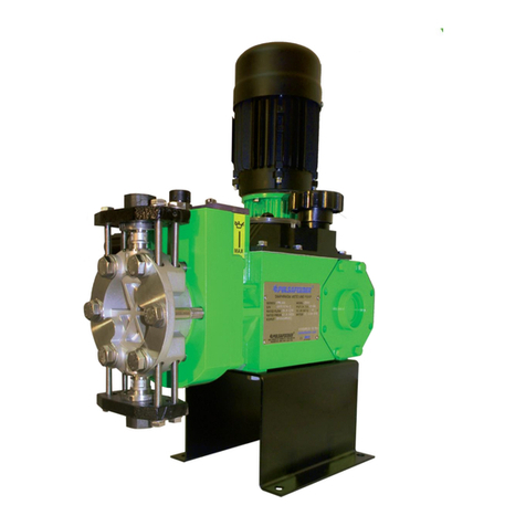
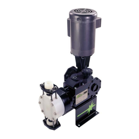
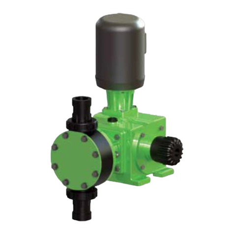
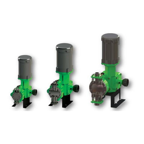
Pulsafeeder PulsaPro PP7440 Instruction manual

PulsaPro
®
HYDRAULIC DIAPHRAGM
METERING PUMPS
PP7440
Installation, Operation &
Maintenance Manual
Bulletin: IOM-PRO-003 Rev A

PULSAFEEDER FACTORY SERVICE POLICY
Should you experience a problem with your PulsaPro pump, consult the troubleshooting
guide in your operation and maintenance manual. If the issue is not covered or cannot be
solved, contact your Pulsafeeder Sales Representative; or contact the Pulsafeeder Service
department directly.
Parts purchased to correct a warranty issue may be credited after an examination of original
parts by Pulsafeeder. Warranty parts returned as defective, which test good, will be sent back
freight collect. No credit will be issued on any replacement electronic parts. If the product requires
returning to the factory for inspection and/or repair, a Return Authorization Number (RMA) issued
by Pulsafeeder is mandatory. To request an RMA, contact your local sales representative for an
authorization form.
TRADEMARKS
PulsaPro® is a registered trademark of Pulsafeeder, Inc.
Pulsafeeder® is a registered trademark of Pulsafeeder, Inc.
SAFETY CONSIDERATIONS
•
Read and understand all related instructions and documentation before
attempting to install or maintain this equipment
•
Observe all special instructions, notes, andcautions.
•
Act with care and exercise good common sense and judgment during
allinstallation, adjustment, and maintenanceprocedures.
•
Ensure that all safety and work procedures and standards that are applicable to
yourcompany and facility are followed during the installation, maintenance, and
operation of this equipment.
Copyright ©2022 / 2020 Pulsafeeder, Inc. All rights reserved.
Information in this document is subject to change without notice. No part of this publication may be
reproduced, stored in a retrieval system; or transmitted in any form or any means electronic or
mechanical, including photocopying and recording for any purpose other than the purchaser’s
personal use without the written permission of Pulsafeeder, Inc.
CONVENTIONS
A WARNING DEFINES A CONDITION THAT COULD CAUSE DAMAGE TO BOTH
THE EQUIPMENT AND THE PERSONNEL OPERATING IT. PAY CLOSE
ATTENTION TO ANY WARNING.
NOTES ARE GENERAL INFORMATION MEANT TO MAKE OPERATING THE
EQUIPMENT EASIER.

Page 3 of 48
Table of Contents
Pulsafeeder Factory Service Policy……………………………………...……...…… 1
Trademarks………………………………………………………………....…...……. 1
Safety Considerations…………………………………………………………....…… 1
1. Introduction………………………………………………………………………. 5
1.1 Receiving Inspection………………………………………………………………. 5
1.2 General Information………………………………………………………………… 5
1.3 Personnel Responsible for Pump Operation…………………………………. 5
1.4 Testing………………………………………………………………………………. 5
1.5 Warranty……………………………………………………………………………. 5
1.6 Requesting Spare Parts………………………………………………………… 5
1.7 Spare Parts…………………………………………………………………………. 6
1.8 Liability Exclusion…………………………………………………………………… 6
1.9 Restrictions Regarding this document…………………………………………. 6
2. Transport and Storage…………………………………………………………. 6
2.1 Consignment receipt and unpacking…………………………………………… 6
2.2 Handling……………………………………………………………………………… 6
3. Storage Instructions……………………………………………………………. 7
3.1 Short Term…………………………………………………………………………... 7
3.2 Long Term…………………………………………………………………………… 7
4. Principles of Operation………………………………………………………... 7
4.1 Overall Operation…………………………………………………………………… 7
4.2 Nameplate Identification………………………………………………………… 8
4.3 Flow Rate…………………………………………………………………………. 9
4.4 Intended Use……………………………………………………………….……… 9
4.5 Components and Operation…………………………………………………… 9
5. Installation………………………………………………………………………. 14
5.1 Location……………………………………………………………………………. 14
5.2 Ideal Metering Pump Installation……………………………………………… 14
5.3 Suction Pressure Requirements……………………………………………… 15
5.4 Discharge Pressure Requirements…………………………………………… 16
5.5 PULSAlarm Leak Detection Electrical Connections……………………… 16
6. Equipment Setup………………………………………………………………. 17
6.1 Hydraulic Oil Fill…………………………………………………………………… 17
6.2 Drive Motor Installation…………………………………………………………… 17
6.3 Drive Motor Wiring………………………………………………………………… 18
6.4 Motor Rotation………………………………………………………………….… 18
7. Startup Procedure………………………………………………………………… 18
7.1 Output Adjustment………………………………………………………………… 18
7.2 Suction System……………………………………………………………………. 18
7.3 Priming the Pump Head…………………………………………………………. 18
7.4 Priming the Reagent Head………………………………………………………. 18
7.5 Calibration…………………………………………………………………………. 18
8. Maintenance………………………………………………………………………... 20
8.1 Operating Precautions……………………………………………………………. 20
8.2 Consulting with Technical Documentation……………………………………… 20
8.3 Oil Changes………………………………………………………………………... 20
8.4 Wet End Removal, Inspection, and Reinstallation……………………………. 23
8.5 Priming……………………………………………………………………………… 26

Page 4 of 48
8.6 Check Valves……………………………………………………………………… 28
8.7 Hydraulic Performance Valve (HPV)………………………………………… 30
8.8 Hydraulic Bypass Valve (HBV)…………………………………………………. 31
8.9 Push to Purge (PTP)…………………………………………………………… 31
8.10 Piston Seals……………………………………………………………………… .32
8.11 Oil Seal……………………………………………………………………………. 34
8.12 Pump Motor Removal and Reinstallation……………………………………... 34
9. Troubleshooting……………………………………………………………….34
10. Technical Service Support………………………………………………... 35
10.1 Authorized Service Centers……………………………………………………. 35
10.2 Local Sales Representatives………………………………………………… 35
10.3 Factory Service Support………………………………………………………… 35
11. APPENDIX I……………………………………………………………………. 36
11.1 PULSAlarm Leak Detection System………………………………………… 36
11.2 PULSAlarm Leak Detection Diaphragm……………………………………. 36
11.3 Priming of Leak Detection Diaphragm……………………………………… 40
12. APPENDIX II……………………………………………………………………. 41
12.1 Piping Calculations……………………………………………………………. 41
12.2 System Back Pressure………………………………………………………. 42
12.3 Nomenclature……………………………………………………………………. 43
13. APPENDIX III………………………………………………………………….... 44
13.1 Oil Specification………………………………………………………………. ….. 44
14. APPENDIX IV……………………………………………………………...……... 45
14.1 Bolt Torque Recommendations………………………………………………... 45
15. APPENDIX V……………………………………………………………...……...46
15.1 Pulsatrol Pulsation Dampener…………………………………………………... 46
15.2 Back Pressure Valve………………………………………………………….... 47
15.3 Pressure Relief Valve…………………………………………………………… 47

Page 5 of 48
1. Introduction
THIS DOCUMENT CONTAINS INFORMATION TO BE USED BY QUALIFIED PERSONNEL ONLY
1.1 Receiving Inspection
All materials relative to supply are delivered to the shipper in perfect condition after thorough final
testing and packaging. Inspect goods immediately upon receipt and check:
oThe goods received correspond to the order made
oThe packaging has not undergone damage due to transport or has not been tampered with
oThe actual condition of goods
If anomalies or damage are found immediately issue a complaint with the courier and inform
Pulsafeeder aftermarket service at Proservice@idexcorp.com or call Pulsafeeder at 585-292-8000.
1.2 General Information
The purpose of these instructions is to refer information deemed necessary for understanding as
much as possible about and facilitating the installation, commissioning, use and maintenance of
hydraulic diaphragm metering pumps.
1.3 Personnel Responsible for Pump Operation
Anyone operating the pump should have read and understood the instructions set forth within this
manual. The employer must instruct all staff on the risks of accidents and on devices and clothing
to be used for individual safety.
1.4 Testing
Each Pulsafeeder metering pump is a reliable quality product, subject to careful final inspection to
ensure their proper functioning and found compliance with the specified performance. The final test
results, if specifically requested by contract, are registered and made available to the customer.
Pulsafeeder offers many different tests available with your PulsaPro pump.
1.5 Warranty
PulsaPro metering pumps are guaranteed for a period of eighteen (18) months from the date of
shipment. Drive assemblies (gearing, shafts, eccentric, and related components within gearbox)
are guaranteed for a period of sixty (60) months from the date of shipment. The guarantee covers
replacement, free of charge, of any component found to be defective in material or processing by
the Aftermarket Service Group at Pulsafeeder, Inc.
The Warranty is NOT valid in the following cases:
oComponents subject to normal wear (gaskets, seals, O-rings)
oInstallation and/or use do not meet the technical conditions of sale and instruction
oIf the pump has been tampered with or disassembled
oMotor (drive) is covered by the motor manufacturer
1.6 Requesting Spare Parts
For preventative maintenance, Pulsafeeder recommends the installation of a KOPkit (Keep-On-
Pumping), which includes the recommended spare parts needed. The part number for this kit can
be located on the pump nameplate as well as the specification data sheet provided with your
metering pump.
For other needed components, find and study the sectional drawings of the pump in use, if
necessary, contact Pulsafeeder to obtain a copy. For drawings and bill of materials for your
drawing, make a list of the parts needed and send to your local Pulsafeeder sales representative,
always specify the pump serial number.

Page 6 of 48
To find the local Pulsafeeder representative for parts pricing and availability log onto
www.pulsafeeder.com, select “Sales Contacts”. For assistance with determining the representative
then please contact us at 585-292-8000
1.7 Spare Parts
Modifications are not allowed. Original Pulsafeeder spare parts and accessories are to be used to
assure conformity with safety rules. Pulsafeeder declines any responsibility in case of use of non-
original parts and which results in the warranty being voided.
1.8 Liability Exclusion
Attempts to disassemble, modify, or tamper in general by unauthorized personnel will void the
warranty and will release Pulsafeeder from any liability for damage caused to persons or property
resulting from such actions.
Pulsafeeder is considered released from any liability in the following cases:
oImproper Installation
oImproper use of the machine by non-professional or inadequately trained operators
oUse not in compliance with regulations in the Country of use
oLack of maintenance or improperly performed
oUse of non-original spare parts or incorrect parts for model in question
oTotal or partial failure to observe the instructions
oException environmental events
1.9 Restrictions Regarding this Document
This document is the property of Pulsafeeder together with the technical information contained in it.
Modification, reproduction, or copying (in part or whole) without written permission is prohibited.
2. Transport and Storage
2.1 Consignment receipt and unpacking
Immediately after receipt of the equipment it must be checked against the delivery/shipping
documents for its completeness and that there has been no damage in transportation.
Check any crates, boxes, or wrappings for any accessories or spare parts that may be packed
separately with the equipment or attached to side walls of the box.
Each product has a unique serial number, check that the number corresponds with that advised,
and always quote this number in correspondence as well as when ordering spare parts.
Shortages or damage should be reported immediately to the carrier and your Pulsafeeder
Representative.
2.2 Handling
Boxes, crates, pallets, or cartons may be unloaded using forklift vehicles or slings dependent on
their size and construction. Slings, ropes, and other lifting gear should be positioned where they
cannot slip and where a balanced lift is obtained. If lifting without equipment, follow safe practices
to avoid injury (i.e., lifting with two people).

Page 7 of 48
3. Storage Instructions
3.1 Short Term
Storage of PulsaPro pumps for up to twelve (12) months is considered short-term. The
recommended short-term storage procedures are:
oStore the pump indoors at room temperature in a dry environment
oConfirm or fill the eccentric box to its normal operating level with PULSAlube Premium 7H
Hydraulic Oil. If required by the operating environment, take steps to prevent entry of water
or humid air into the eccentric enclosure.
oPrior to startup, inspect the housing and gearbox. Replenish hydraulic oil as required to
maintain operating levels. If water or condensation is present, change oil as described
under Equipment Set-Up.
oStart up in accordance with instructions in this manual
3.2 Long Term
Every twelve months, in addition to the above short-term procedures, power up the motor and
operate the pump for a minimum of one hour. It is not necessary to have liquid in the reagent head
during this operation, but the suction and discharge ports must be open to atmosphere. If the pump
is equipped with a PULSAlarm leak detection system, ensure that a vacuum is drawn before
operating the pump. See Appendix I for more information.
After twelve months of storage, Pulsafeeder Warranty cannot cover such items which are subject to
deterioration with age such as seals and gaskets. If the pump has been in storage longer than
twelve (12) months, it is recommended that such items be inspected and replaced as necessary
prior to startup. Materials and labor to replace this class of items under these circumstances are the
purchaser’s responsibility. For continuance of the warranty after extended storage, equipment
inspection and any required refurbishing must be done by a Pulsafeeder Representative.
4. Principles of Operation
4.1 Overall Operation
A piston reciprocates within an accurately sized cylinder at a preset stroke length, displacing an
exact volume of fluid. The piston, however, does not pump various chemicals. The piston and
associated mechanisms are enclosed in a gearbox that also serves as a hydraulic oil reservoir. A
diaphragm separates the oil from the product pumped. The diaphragm moves in exact response to
piston displacement. The diaphragm does no work and acts only as a separator. Consequently,
the oil displacement is translated into equal product displacement. The piston retraction causes the
product to enter through the suction check valve. Piston advancement causes the discharge of an
equal amount of product through the discharge check valve.
Individual pumps may vary in appearance due to various liquid ends, accessories, and multiplexing.
The basic principles of operation, however, remain the same.
The maximum A-weighted sound pressure level of the Pulsa Pro 7440 series metering pump was
tested and determined to be 59 dBA.

Page 8 of 48
Figure 1
4.2 Nameplate Identification
Each pump carries a nameplate for identification with the following information:
oModel Series
oSerial Number
oRated Flow
oRated Pressure
oKOPkit (recommended spare
parts)
oPiston Diameter
oGear Ratio
oMotor Frame Size, RPM
Rating
Figure 2

Page 9 of 48
4.3 Flow Rate
PulsaPro has pulsating flow rates, generated by the alternating movement of the piston and the
action of the check valves on the pump head which determine flow direction. Pump flow rate is
adjustable and increases or decreases in direct proportion to the variation of the stroke adjustment.
The theoretical flow rate –corresponds exactly to the volume described by the movement of the
diaphragm.
The actual flow rate –is inevitably lower than the theoretical flow rate, due to the volumetric
efficiency of the pump. It varies depending on the type and size of the pump, the nature and
viscosity of the liquid to be pumped, working pressure, etc.
4.4 Intended Use
PulsaPro 7440 Pumps are designed for dosing liquid fluids (flammable, acids, alkaline, solvents,
etc.) at ambient temperature or heated, suitable for continuous service.
These pumps are used in the following markets:
-Chemical Processing, Petrochemical, Oil & Gas, Power & Energy, Water/Wastewater
treatments, and General Industries.
Applications may include but not limited to:
-Amines, Defoamers, Oxygen Scavengers, Disinfectants, Oil Additives, Acids, Demulsifiers,
Caustics, Methanol, Biocides, Corrosion Inhibitors, Ethylene Glycol, Anti-Scalants, and other
chemical feeds.
4.5 Components and Operation
Reagent Head (Wet End) –The typical reagent head assembly consists of the reagent head,
diaphragm, and the suction/discharge check valves. This assembly is the only part of the pump to
contact the process liquid; consequently, maintenance is critical to pump performance.
Figure 3

Page 10 of 48
Types of Diaphragms –PulsaPro 7440 offer the Flat Diaphragm and HYDRAtube. Additionally,
you can utilize our Double Diaphragm (Flat) with PULSAlarm Leak detection. (Figure 4 showing the
Flat diaphragm and HYDRAtube.
Figure 4
Flat Diaphragm –is the standard design ensuring high performance metering in a
leak-free operation. PulsaPro flat diaphragms are available in a variety of both
metal and plastic materials and can handle a wide range of chemicals. As with
PulsaPro diaphragm constructions, the flat diaphragm is hydraulically balanced
and operates stress free, providing exceptional life and accuracy.
Figure 5
HYDRAtube –is the best choice for sheer sensitive, high viscosity fluids and
slurries. It’s straight flow through design eliminates clogging and flow restrictions.
It offers double diaphragm safety as a standard as well as optional slurry valves.
Available in FKM, CSM, or PFA, it can be utilized with the most corrosive or acidic
chemicals. Optional ChemAlarm leak detection system monitors the electrical
conductivity of the intermediate liquid between the HYDRAtube and second
diaphragm to detect diaphragm failure and, can signal an alarm or stop the pump.
Figure 6

Page 11 of 48
Double Diaphragm (Flat) with PULSAlarm Leak Detection –offers a rugged
sandwich style double diaphragm construction for increased protection against
leaks. PULSAlarm provides a pressurized leak detection technology to monitor
the diaphragm integrity and can signal an alarm or stop the pump at the first sign
of diaphragm failure. PULSAlarm is designed to contain full rated pressure up to
3,000 PSI (207 BAR), and is rated NEMA Type 7, EEMAC7 Class 1, Division 1,
Groups C&D, Class 1, Zone 1, Groups IIA&IIB; UL, cUL, CE, ATEX. An optional
pressure gauge is also available for visual indication of diaphragm integrity at the
pump.
Figure 7
Pump Head Assembly –attached to the intermediate head of the pump, it consists of the pump head,
cylinder, piston assembly, and three hydraulic valves.
Push-To-Purge (PTP) –situated at the top of the pump head
automatically removes gases from the hydraulic system during
normal operation. Momentary manual actuation of the external
valve button overrides automatic operation to validate priming or
to determine diaphragm integrity.
Figure 8
Hydraulic Performance Valve (HPV) –integrated within the
dish plate this valve automatically maintains the required
hydraulic oil volume by replacing any oil lost past the piston or
through the PTP valve.
Figure 9

Page 12 of 48
Hydraulic Bypass Valve (HBV) –this valve protects the pump
from over-pressurization by relieving any excess pressure in the
pump’s hydraulic system. The valve is preset based on
customer’s specification, typically adjusted to 10% above the
system pressure. The sight glass above the valve allows visual
aid to observe the operation.
Designed to protect the pump only, does not provide
an overall system protection.
Figure 10
Manual Control/Stroke Adjustment
The PulsaPro 7440 pump flow rate is adjusted by changing the stroke length utilizing a counter located
next to the handwheel which denotes the stroke position. The stroke is adjusted by turning the control
knob to the desired setting. The stroke length percentage is denoted by a counter.
NOTE: Stroke Adjustment is measured to the tenths. The below picture represents 100.0% stroke.
Figure 11

Page 13 of 48
Automatic Stroke Adjustment
If ordered with a controller you would have the XAE which is a microprocessor-based stroke length
control device. The unit is physically attached and integrated into the pumps design. This controller
allows for precise adjustment of output flow of a process media by means of stroke length position. For
additional information on your XAE please download or review a copy of the IOM.
Figure 12
Gear Ratio Assembly/Motor Adaptor
PulsaPro pumps are driven by a standard C-face electric motor mounted on the adaptor input flange.
The motor drives a set of worm gears located in the gearbox which will then convert rotational speed
into torque. They in turn power the eccentric shaft assembly that converts rotary motion into
reciprocating motion. The motor adaptor is available in a variety of sizes to accommodate different
motor frame specifications.
Figure 13
More than one pump can be driven through a single drive assembly, which is referred to as multiplexing.
The pumps are mounted on a common gear reducer assembly on the drive pump and the pump without
a gear reducer is called the driven pump. Each pump is mounted on its respective standard simplex
base. Each pump will have its own gear ratio.

Page 14 of 48
Whenever pumps are multiplexed, the eccentric shafts are positioned to place a uniform load on the
driver. Before full disassembly, always note the relative positions of the eccentric shafts to each other
so they can reassemble in the same orientation.
5. Installation
5.1 Location
When selecting an installation site or designing a skid package, consideration should be given to access
for routine maintenance.
PulsaPro pumps are designed to operate indoors and outdoors, but it is desirable to provide a hood or
covering for outdoor service. External heating may be required if ambient temperatures are below -40°F
are anticipated. Check with the factory regarding suitability of the operating environment.
The pump must be rigidly bolted to a solid and flat foundation to minimize vibration, which can loosen
connections. When the pump is bolted down, care must be taken to avoid distorting the base and
affecting alignments, check for levelness when securing. This will assure that the hydraulic oil is
maintained at the proper levels and that the check valves can operate properly.
5.2 Ideal Metering Pump Installation
Figure 14

Page 15 of 48
All piping systems should include:
oShutoff valves and unions (or flanges) on suction and discharge piping. This permits
check valve inspection without draining long runs of piping. Shutoff valves should be
the same size as connecting pipe. Ball valves are preferred since they offer minimum
flow restriction.
oAn inlet strainer, if the product is not a slurry. Pump check valves are susceptible to dirt
and other solid contaminants unless designed for that service, and any accumulation
can cause a malfunction. The strainer should be located between the suction shutoff
valve and the pump suction valve. It must be sized to accommodate the flow rate and
the anticipated level of contamination; 100 mesh screens are recommended.
oVacuum/pressure gauges in the suction and discharge lines installed to check system
operation. Gauges should be fitted with protective shutoff valves for isolation while not
in use.
oA separate system relief valve to protect piping and process equipment, including the
pump, from excess process pressures.
Piping weight must not be supported by the valve housings or other portions of the reagent head, as the
resulting stresses can cause leaks. If appropriate, provide for thermal expansion and contraction so
that no excess force or moments are applied to the pump.
If piping assembly, use a sealing compound chemically compatible with the process material.
Users of sealing tape are cautioned to ensure that the pipe thread ends are not taped. Both new and
existing piping should be cleaned, preferably by flushing with a clean liquid (compatible with process
material) and blown out with air, prior to connection to the pump. Flow issues at pump startup are often
related to the check valves being fouled with piping and process debris.
5.3 Suction Pressure Requirements
Although PulsaPro metering pumps have suction lift capability, all pump installations should have
minimum lift for optimum performance. A flooded suction (i.e., suction pressure higher than
atmospheric pressure) is preferable whenever possible. The pump should be located as close as
possible to the suction side reservoir or other source.
Piping should be sized to allow for best possible NPIP conditions.
IT IS NOT RECOMMENDED TO INSTALL A PUMP EQUIPPED WITH A PULSALARM LEAK
DETECTION IN A SUCTION LIFT SYSTEM
If suction lift is required, the net positive suction pressure required (NPSHr) is 0.21 bar (or 3
psia). If this requirement is not met the process liquid may cavitate inside the pump, degrading
metering accuracy. To maintain prime on a suction installation, a foot valve is required. In
addition, suction pressure must be maintained at a minimum absolute value of 0.35 bar (or 5
psia) to ensure proper hydraulic system and proper pump operation.
IT IS CRITICAL THAT PULSAPRO PUMPS HAVE FREE FLOWING AND UNOBSTRUCTED
SUCTION CONDITIONS AT ALL TIMES. CLOSED VALVES, CLOGGED STRAINERS,
OBSTRUCTED PIPING, ETC. ARE TO BE AVOIDED. SUCTION RESTRICTIONS CAN PLACE
STRESS ON THE DIAPHRAGM THAT MAY RESULT IN PREMATURE FAILURE.
Refer to Appendix II for procedures for the calculation of suction pressure.

Page 16 of 48
5.4 Discharge Pressure Requirements
PulsaPro Metering Pumps are designed for continuous service at the rated discharge pressure. If
system suction pressure exceeds system discharge pressure, flow would be generated in addition
to that caused by the pump, resulting in a reduction in accuracy and loss of control over the
metering process. To prevent this condition, commonly referred to as “flow-through”, discharge
pressure must exceed suction pressure by at least 20 PSI (1.37 BAR). The installation of a back-
pressure valve can achieve this is necessary to achieve the differential pressure.
Discharge systems should be protected from excessive pressures by utilizing a pressure relief or
pressure limiting valve in the piping system. Operation of the pump at pressure above its rated
maximum (found on nameplate) may result in damage to the pump components and/or unsafe
system conditions.
Refer to Appendix II for procedures for the calculation of discharge pressure.
5.5 PULSAlarm Leak Detection Electrical Connections
If equipped with an optional pressure switch, install electrical wiring and conduit in accordance with
local electrical codes.
Figure 15
The switch is rated as follows:
Voltage
115VAC
Phase
Single
Load
1.0 Amp (Resistive)
Contacts
NO/NC (SPDT)
Connection
Flying Leads, 20AWG
Max Pressure
3000PSI
The switch is the SPDT (single pole, double throw) type and can therefore be connected to either
open or to close upon detection of a diaphragm leak condition. Contacts
or wires are identified as follows:
Normally Open (NO) Wire Color White
Normally Closed (NC) Wire Color Red
Common (COM) Wire Color Black
THE ENCLOSURE IS LABELED WITH APPLICABLE SAFETY
AGENCY RATINGS FOR HAZARDOUS AREA INSTALLATION. SINCE THE SWITCH IS OF
THE MECHANICAL CONTACT TYPE, IT CAN NEVER QUALIFY AS NON-SPARKING (NON-
INCENDIVE, OR “M”) FOR OCCASSIONAL AND SHORT-TERM HAZARDOUS AREA USE.
PROTECTION MUST BE PROVIDED BY THE ENCLOSURE.
Go to Section 11 Appendix I for further description and instructions for the PULSAlarm Leak
Detection System.

Page 17 of 48
6. Equipment Setup
6.1 Hydraulic Oil Fill
The PulsaPro ships from the factory pre-filled with oil after testing is completed. When starting up
you can verify the oil level from the provided sight glass on the gearbox as well as the Intermediate
Head.
Figure 16
Figure 17
Remove the oil fill cap on the rear of the gearbox to gain access to the gear oil reservoir and add
PULSAlube 8GS gear oil. For the hydraulic oil, remove the plastic cover on the top of the
intermediate chamber cover and add PULSAlube 7H hydraulic oil. High oil level will not affect the
operation of the pump; however, it can result in nuisance leakage of oil.
Oil Type
Color
Amount
Hydraulic
Purple
3 Liters
Gear
Amber
1.75 Liter
6.2 Drive Motor Installation
PulsaPro pumps may be shipped with the drive motor packed separately. This is done to avoid damage
during transport.
oRemove the unattached coupling half from the motor adaptor. Ensure that the elastomer
coupling spider remains in place, on the coupling half that remains attached to the worm shaft in
the pump.
oIf applicable, remove any tape or retainer rings that hold the motor shaft key in place.
oPlace the loose coupling half on the motor shaft. Align the face of the motor shaft flush with the
face of the coupling.
oTighten the setscrew onto the shaft key
oPlace the motor in a vertical position and align the coupling teeth
oInstall the motor downwards onto the adaptor. Final position can be achieved by slightly
rotating the motor until the coupling jaws align
oRotate the motor until the clearance holes in the adaptor and the tapped holes in the motor
align. Fasten the motor to the adaptor using the supplied bolts (4). Tighten bolts evenly to
secure motor.
Figure 18

Page 18 of 48
6.3 Drive Motor Wiring
Wire the PulsaPro drive motor according to the motor vendor’s nameplates and instructions, and
according to any appropriate national and local electrical codes and regulations.
6.4 Motor Rotation
Verification of the motor direction is necessary at startup. The motor direction must be counterclockwise
as indicated on the gearbox by a directional arrow.
Figure 19
7. Startup Procedure
7.1 Output Adjustment
All PulsaPro pumps have a handwheel for manual stroke length
adjustment. Mounted on the top of the stroke adjustment housing,
the hand-knob can be adjusted at any point (from 0 to 100% stroke
setting) by rotating the hand wheel as required. A counter, located
next to the handwheel will denote the stroke position.
Adjustments can be made while the pump is at rest or operating,
although operating adjustments are easier to make.
Figure 20
NOTE: Stroke Adjustment is measured to the tenths. The below picture represents 100.0% stroke
IF THE PUMP IS EQUIPPED WITH A PRESSURE LEAK DETECTION SYSTEM, THE SYSTEM
MUST REMAIN SEALED AT ALL TIMES DURING PUMP OPERATION, WHETHER OR NOT LEAK
DETECTION IS REQUIRED. IF THE SEAL IS BROKEN, DECREASED FLOW AND/OR DIAPHRAGM
DAMAGE WILL OCCUR. SEE APPENDIX I FOR FURTHER INFORMATION
LEAK DETECTION DIAPHRAGM SYSTEMS REQUIRE SPECIAL HYDRAULIC PRIMING
CONSIDERATIONS TO PROTECT THE DIAPHRAGM FROM DAMAGE DURING INTIAL PUMP
STARTUP. SEE APPENDIX I FOR FURTHER INFORMATION.
7.2 Suction System

Page 19 of 48
Before operation of any PulsaPro pump, carefully ensure that all suction valves are in the open position.
Verify that all filters and strainers are clean and clear. Ensure that any other potential causes of
restriction have been addressed. Unrestricted flow of liquid to the suction side of the pump is critical to
proper operation.
7.3 Priming the Pump Head
All pumps are shipped with a fully primed hydraulic system. However, during shipping and handling
some air may enter the hydraulic system. Generally, this air will be automatically purged after a short
run-in period. If necessary, rapid purging may be accomplished by fully depressing and holding the
PTP valve for five to ten seconds, while the pump is operating. Repeat as necessary until the pump
stabilizes at rated flow.
7.4 Priming the Reagent Head
oOpen the suction and discharge line shutoff valves
oIf the piping system design and the storage tank are such that the product flow due to gravity
through the pump, no priming is required. In the event the discharge line contains a significant
amount of pressurized air or other gas, it may be necessary to lower the discharge pressure to
enable the pump to self-prime.
oIf the installation involves a suction lift, it may be necessary to prime the reagent head and
suction line. Try priming the reagent headfirst. Remove the discharge valve by unscrewing the
four tie bar bolts and removing the valve as a unit. Fill the head through the discharge valve
port with process (or compatible) liquid, then reinstall the valve and retighten the tie bar bolts to
the recommended specification.
oStart the pump at the 0% stroke length setting and slowly increase the setting to 100% to prime
the pump. If this does not work, it will be necessary to fill the suction line.
oFilling of the suction line will necessitate the use of a foot valve or similar device at the end of
the suction line so that liquid can be maintained above the reservoir level. Remove the suction
valve assembly, fill the line, replace the valve, then remove the discharge valve assembly and
fill the reagent head as described in the third step above. The pump will now self-prime when
started up per step four above.
7.5 Calibration
All metering pumps must be calibrated to accurately specify stroke length settings for required flow
rates.
A typical calibration charge is shown in figure 23. Although
output is linear with respect to stroke length setting, an
increase in discharge pressure decreases output uniformly,
describing a series of parallel lines, one for each pressure
(only two are shown).
The theoretical output flow rate at atmospheric output
pressure is based on the displacement of the hydraulic
piston (the product of piston cross-sectional area and
stroke length) and the stroking rate of the pump. With
increasing the discharge pressure there is a corresponding
decrease in output flow of approximately 1% per 100 PSI
(7 BAR) increase in output pressure. Whenever possible,
calibration should be performed under actual process
conditions (i.e., the same or a similar process liquid at
system operating pressure).
To assure a sound hydraulic system, run the pump for ten to fifteen minutes prior to calibration. This will
allow the PTP valve to purge any air from the system.
Figure 21

Page 20 of 48
To construct a calibration chart, measure the flow rate several times at three or more stroke settings
(i.e., 25, 50, 75, and 100), plot these values on linear graph paper, and draw a best fit line through the
points. For stable conditions, this line should predict settings to attain required outputs. See figure 2 for
example of a four-point test plotted onto a calibration chart.
Checking the actual flow rates is especially important in pumps producing low flow rates and operating
against high discharge pressures. In this type of system, normal losses of efficiency can result in lack of
measurable flow at shorter piston stroke lengths. This is a function of the system conditions and does
not indicate a problem with the pump. Careful measurement of actual pump flow at several test points
will allow for proper calibration over the complete flow range.
Figure 22
8. Maintenance
Accurate records from early stages of pump operation will indicate the type and levels of required
maintenance. A preventative maintenance program based on such records will minimize operational
problems. It is not possible to forecast the lives of wetted parts such as diaphragms and check valves.
Since corrosion rates and operational conditions affect functional material life, each metering pump
must be considered according to its service conditions.
Each PulsaPro pump is provided with an individual specification data sheet included in the parts list
package. The data sheet contains important information relating to the application along with the pump
serial number and pump specifications (i.e., materials, piston size, stroking rate, etc.).
PulsaPro KOPkits (Keep-On-Pumping) contains all the replacement parts normally used in preventative
maintenance program. It is always recommended that KOPkits and PULSAlube hydraulic oil be kept
available. A good instruction manual, parts list, and a good maintenance record are key to long trouble-
free metering pump operation.
BEFORE PERFORMING ANY MAINTENANCE REQUIRING REAGENT HEAD OR VALVE (WET
END) DISASSEMBLY, BE SURE TO RELIEVE PRESSURE FROM THE PIPING SYSTEM AND,
WHERE HAZARDOUS PROCESS MATERIALS ARE INVOLVED, RENDER THE PUMP SAFE TO
PERSONNEL AND THE ENVIRONMENT BY CLEANING AND CHEMICALLY NEUTRALIZING AS
APPROPRIATE. FOLLOW SAFETY MEASURES BY WEARING YOUR PROTECTIVE CLOTHING
BASED ON THE HAZARDOUS.
8.1 Operating Precautions
This manual suits for next models
1
Table of contents
Other Pulsafeeder Water Pump manuals

Pulsafeeder
Pulsafeeder PULSAlarm Pulsa Guide

Pulsafeeder
Pulsafeeder PULSA GLM7 Manual

Pulsafeeder
Pulsafeeder PULSAR 25HJ Instruction manual

Pulsafeeder
Pulsafeeder Chem-Tech 100 Series User manual

Pulsafeeder
Pulsafeeder PULSAR Shadow Series Instruction manual

Pulsafeeder
Pulsafeeder DC6 Manual

Pulsafeeder
Pulsafeeder PULSAR HYPOPUMP2 Manual
Pulsafeeder
Pulsafeeder GLM1 Owner's manual

Pulsafeeder
Pulsafeeder PulsaPro PP680 Instruction manual
Pulsafeeder
Pulsafeeder Isochem GMH8 Series Manual