SandAlert Lite 2nd Edition Page 7
Threshold Threshold
c - High Flow, No Sand d - High Flow, With Sand
The SandAlert Lite unit eliminates the flow noise by placing a threshold automatically just above
the flow related noise signal, and if the signal goes higher than this then it is due to solid impacts,
which can be seen in band das short duration, high energy spikes, as compared with the flow
related noise that is longer duration, and of lower energy. The threshold is visibly higher in d, due
to the higher level of flow related noise.
There is also an option with the SandAlert Lite to utilise the auto-calibration function of the unit in
order to produce a reading in grams/hour (or lbs/hour). It should be noted however, that because of
the number of variables associated with the conversion from IPS to grams/hour, this reading is only
approximate. The calibration is much more accurate if undertaken by manual sampling, such as
injection or filtration.
The SIR reading remains largely unaffected by the variables, as these relate mainly to flow rate and
solids particle parameters and the SIR is independent of both of these.
The SIR is calculated from the sensor output continuously, once a run has been initiated, and the
words “Time Left = xxx” appear in the title bar of the screen. This happens in the background,
whatever the operator is doing on the SandAlert Lite, i.e. even if the operator is transmitting data
via the serial port, the monitoring still continues. If required the SIR can be converted to a solids
mass flow rate by a calibration routine. The SIR is also averaged and can be plotted both on-screen
and stored to file to provide a trend history. The stored data files can be printed on the internal
printer, displayed on the screen, or transferred to another device via the RS232 serial port.
The SIRs are stored, and at the end of each averaging period (operator selectable), the average of all
the SIR samples is calculated and stored to disk for trend analysis.
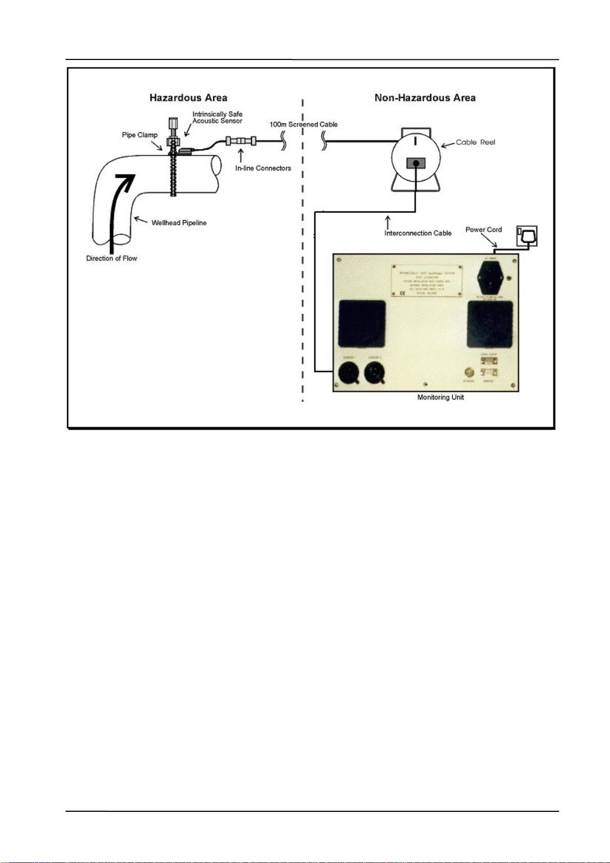
4 Installation
Installation, commissioning and servicing of the system must be strictly in accordance with BS5345
Parts I and IV. All equipment and system approvals, specifications, warranties and statements of
fitness for purpose are conditional upon this requirement being met.
The sensor is certified for use in hazardous areas and it is important to ensure that this level of
certification is adequate for the area in which the sensor is intended to be installed. The SandAlert
Lite unit must be situated in a non-hazardous area.
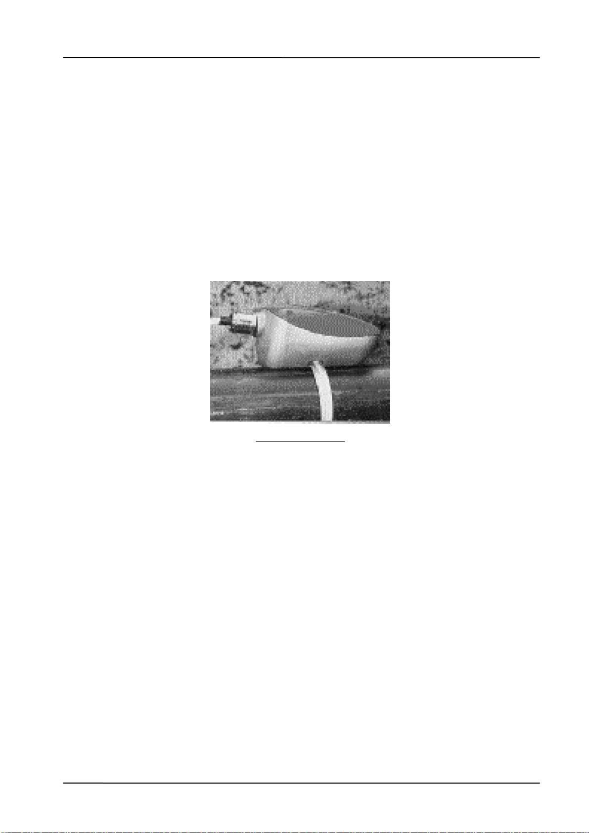
4.1 Sensor Positioning
The acoustic sensor detects the high frequency sound generated by the impacts of sand and other
solid particles e.g. proppant on the inside of the pipe wall. Therefore, the best results will be