manuals.online logo
Brands
  1. Home
  2. •
  3. Brands
  4. •
  5. Pulseroller
  6. •
  7. Industrial Equipment
  8. •
  9. Pulseroller SENERGY User manual

Pulseroller SENERGY User manual

■ Storage method
■ Checks after unpacking the carton
■ General
■ Precautions for use
SENERGY Motor Roller (DC-24V) Installation Manual
NOTE: Control card is not contained. Please purchase it separately.
Thank you for purchasing SENERGY Motor Roller. These instructions contain important information to enable you to use
the products safely and to prevent any harm or damage to you and others. Familiarize yourself with the content before
using the products. After reading this manual, be sure to keep in the assigned place.
● Do not use this product in an explosive atmosphere, flammable gas atmosphere, corrosive atmosphere, a place exposed to water
splashes, or a place close to combustibles. It may cause an explosion, injury, or fire. (Use the waterproof type when the product is
exposed to water splash environment.)
● After confirming the DC power supply, supported voltages and specifications of the Motor Roller, connect them carefully not to make a
mistake.
● Do not conduct such operations as move, installation, connection, and inspection while the power is on. Be sure to conduct such
operations after turning off the power in order to be safe from electric shock.
● Do not use Motor Roller in any way beyond its specifications. It may cause an injury or fire.
● Be sure to ground the frame of the conveyor / equipment.
● Determine the number of Motor Rollers in consideration of the performance/characteristics.
(The motor will generate heat when used in an overload condition, resulting in a shorter product life-cycle.)
● Handle the Motor Rollers with care because the surface temperature of the tube can be high depending on the conditions of use.
● Do not repair, alter, or disassemble Motor Rollers. It may cause an electric shock, injury, or failure.
● Use the Motor Roller in the usage environment of ambient temperatures ranging from -10 to +40°C and relative humidity ranging from
10 to 90% (non condensing).
● Do not apply strong impact, such as dropping or striking the Motor Roller.
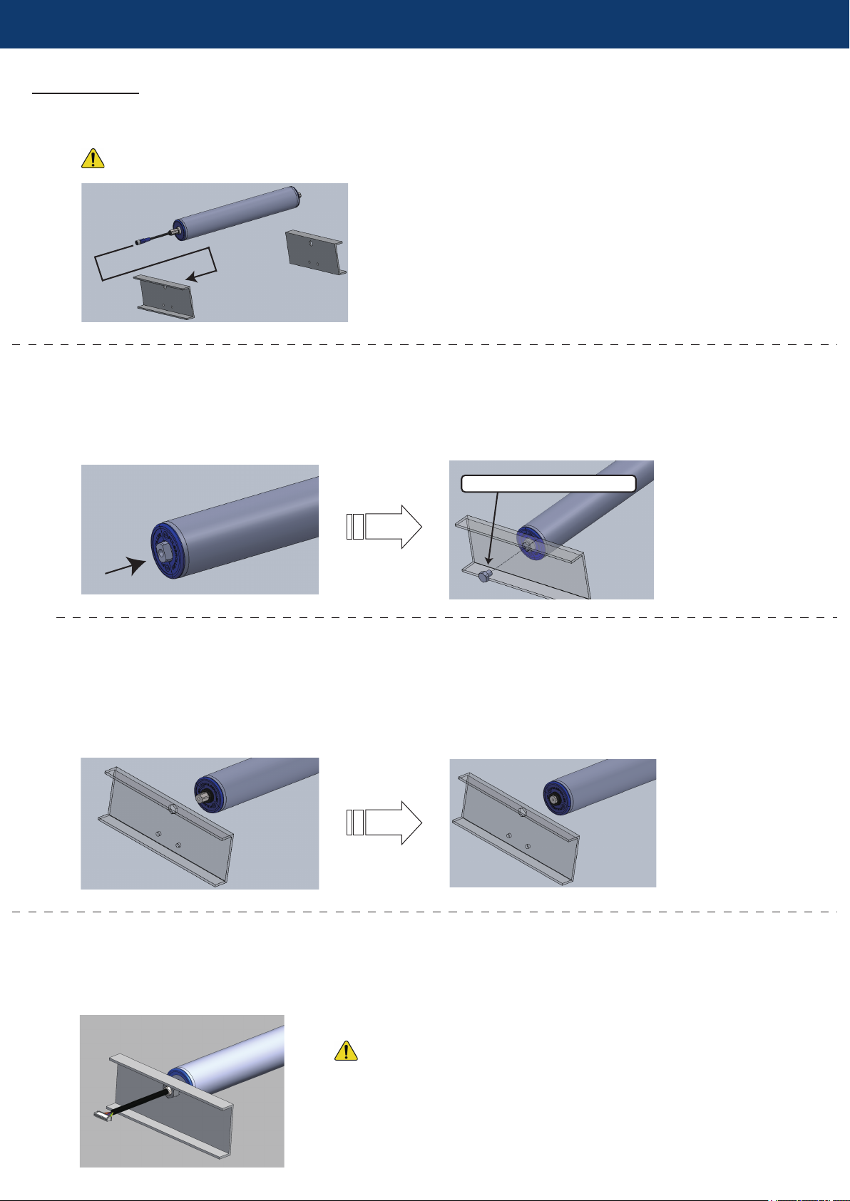
● Do not carry the Motor Roller by holding the cable, and do not pull or replace the connector. Be careful not to damage the wire-coating
while drawing the cable through fixing parts and frame.
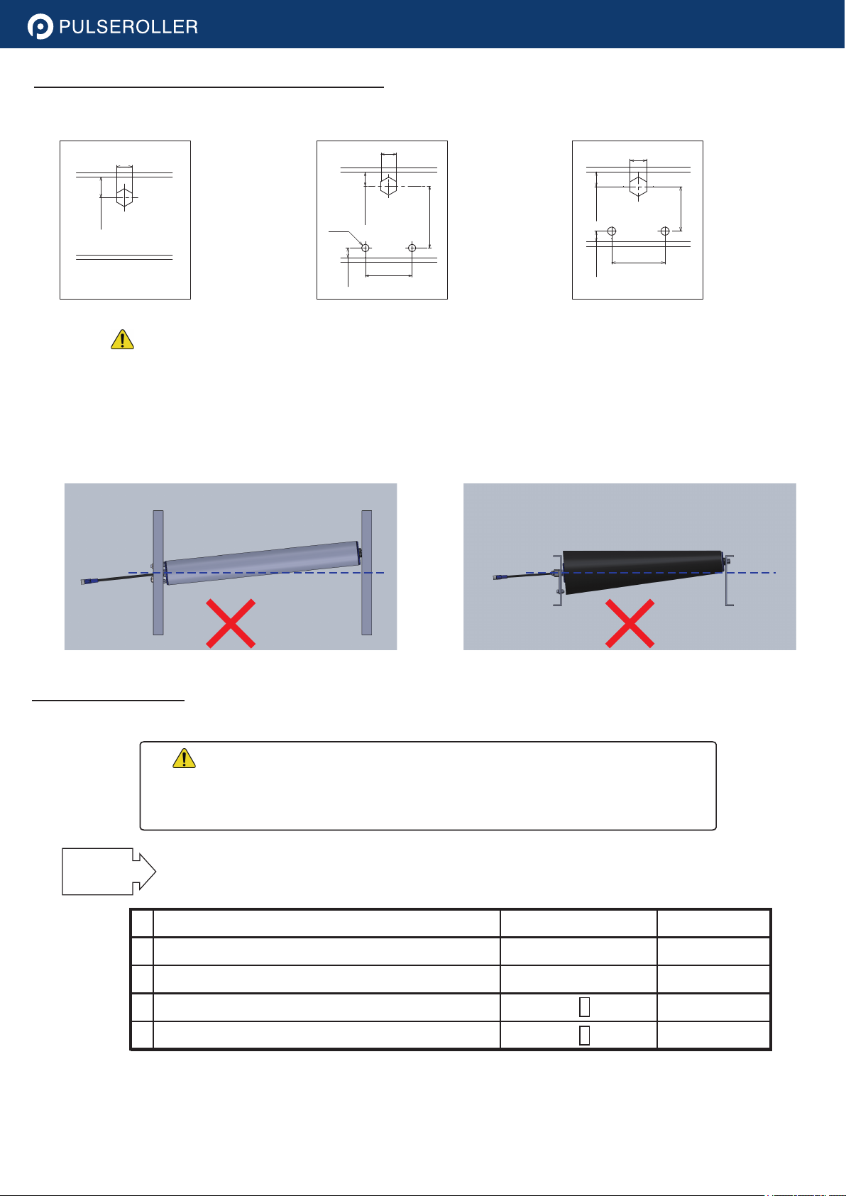
● Mount the Motor Roller and idler rollers in the same level so that they are evenly loaded.
● Never store or leave the Motor Roller outdoors. (It may cause a short circuit or rust.)
● Store the Motor Roller in the environment of ambient temperatures ranging from -30 to +40°C and relative humidity ranging from
10 to 90% (non condensing).
● Store the Motor Roller horizontally because grease is enclosed inside.
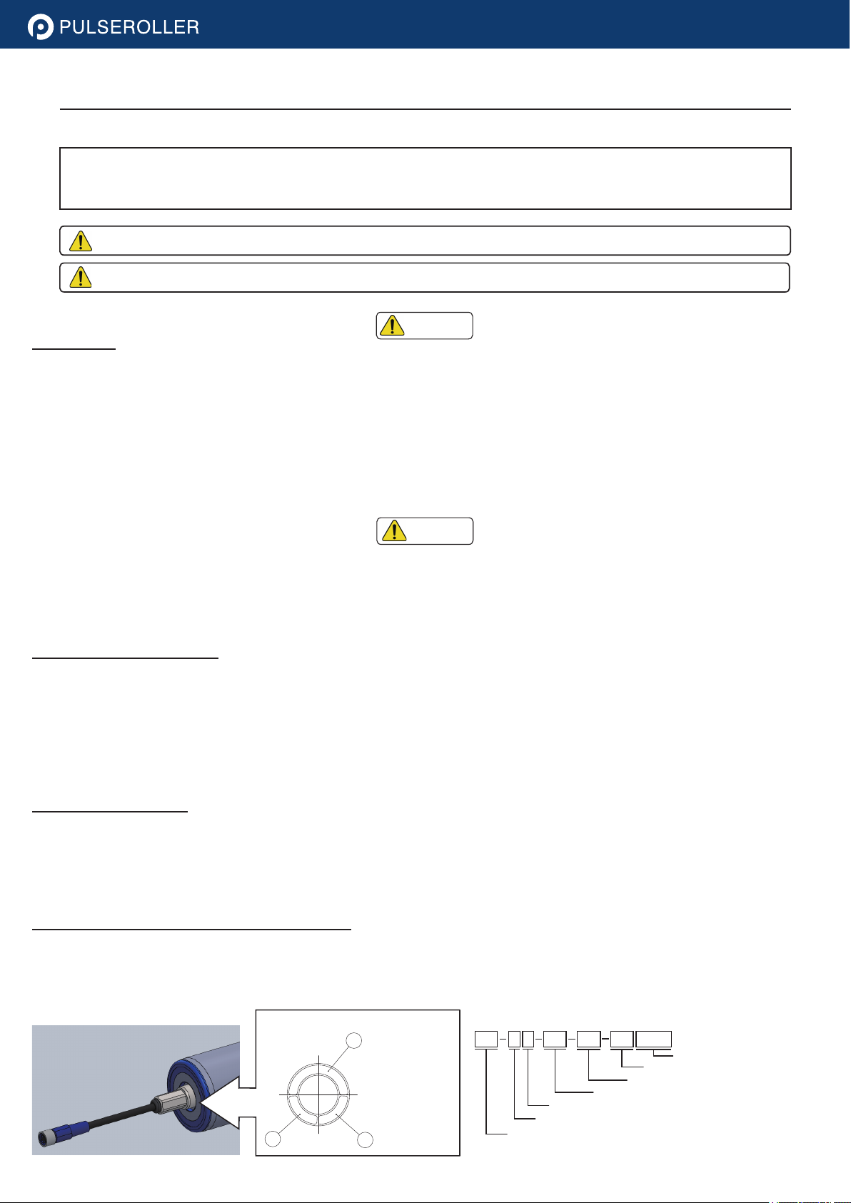
(1) Check the product label on End-plate at the cable side of the Motor Roller to confirm that Part number matches to your order.
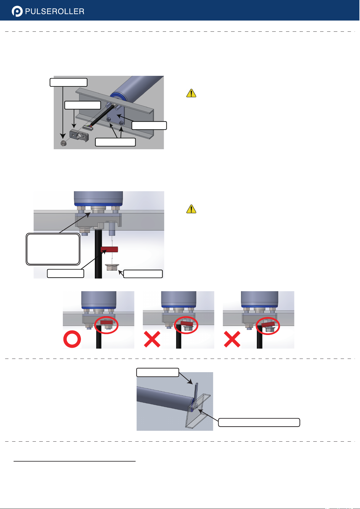
(2) Check that 1 Fixing parts set is included per Motor Roller. (In case of threaded shaft spec, Nut and Washer are included.)
(3) Check the type and Part number of Fixing parts.
Warning: indicates a potentially hazardous situation, which may result in death or serious injury if improperly handled/used.
Caution: indicates a potentially hazardous situation, which may result in injury or property damage if improperly handled/used.
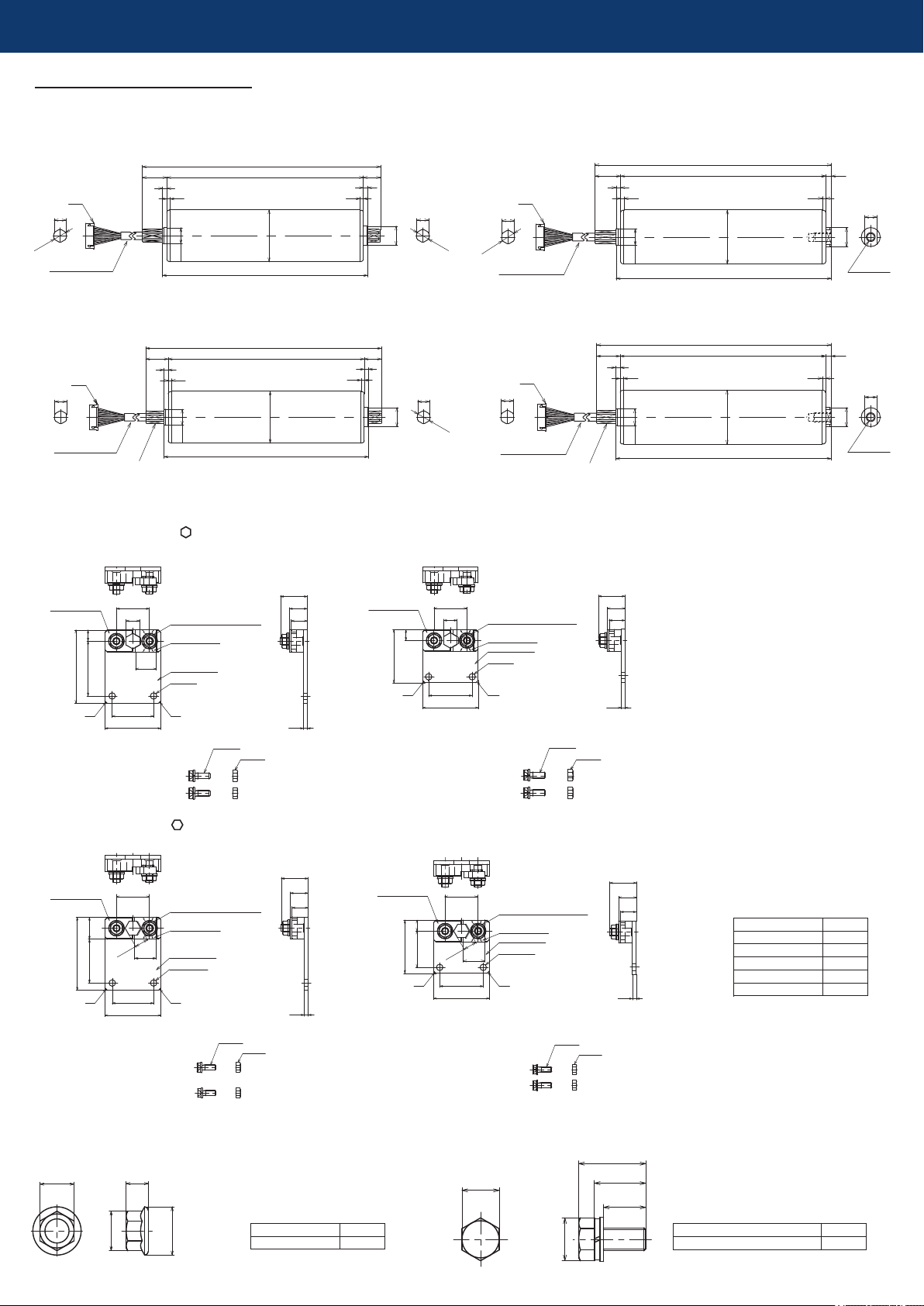
<Label Example>
*For the details of the fields marked with '*', refer to the catalog.
(1) Product Part
number
(2) Power supply
voltage
(3) Serial number
1
0
0
1
0
A
1
D
C
2
4
V
3
F
A
S
A
0
6
-
0
0
5
-
8
4
-
D
A
-
R
P
1
2
3
X
X
X
<Example of Part Number>
PR A D 50 500 60 ZMAT
*Various specifications
Speed code
Roller length
Diameter
DC24V
*Specification
Abbr. of PULSE ROLLER
<Label Example>
Warning
Caution
● M12 threaded Hex shaft + Spring-loaded Hex shaft
■ Dimensional drawing
● Non threaded Hex shaft + Spring-loaded Hex shaft
● Non threaded Hex shaft + M8 drilled and tapped shaft
● M12 threaded Hex shaft + M8 drilled and tapped shaft
● Fixing parts for Non threaded Hex shaft [cable side]
PR-D-30H-FU-N
PR-D-30H-FU-N-ST (Short footprint)
PR-D-30H-PU-N-ST (Short footprint)
PR-D-30H-PU-N
● Fixing accessory for M12 threaded Hex shaft
[cable side]
● Fixing accessory for M8 drilled and tapped shaft
[non-cable side]
Item
M12 Flange nut 1 piece
Item
M8 Hex bolt with captive washer 1 piece
D: Roller diameter (φ48.6/φ50/φ57/φ60.5)
[Point-up brackets: ]
M5 nut
M5 bolt
M5 nut
M5 bolt
46
34
60
9
45
11.1
27
22
14.7
13.2
3.2
2×φ5.3
C2
17
Hex nuts with flange (M6)
Fixing block B
Base bracket
Fixing block A
C2
Hex nuts with flange (M6)
Fixing block B
Base bracket
Fixing block A
46
36
2×φ5.3
C2
44
9
11.1
27
C2
3.2
22
14.7
13.2
[Flat-up brackets: ]
M5 nut
M5 bolt
M5 nut
M5 bolt
60
9
36
27
2×Diaφ5.3
18
Hex nuts with flange (M6)
Fixing block B
Base bracket
Fixing block A
11.1
46
34 C2
C2
22
14.7
13.2
3.2
22
14.7
13.2
3.246
36
44
9
30
27
2×Diaφ5.3
C2
18
Hex nuts with flange (M6)
Fixing block B
Base bracket
Fixing block A
11.1
C2
Items
Base bracket
Fixing block A
Fixing block B
M5 bolt and nut
M6 flange nut
1 piece
1 piece
1 piece
2 sets
2 pieces
13
23.5
18
15
14.8
17
19.6
11
24
11.1 0
-0.1
L=RL+39
23
4
RL
3
3
BF=RL+8
φ15
D
11.1 0
-0.1
φ12
φ18
16
4
JST
φ12
Cable length (Black)
600 mm
11.1 0
-0.1
L=RL+28
23
4
RL
3
3
BF=RL+9
φ15
D
5
φ12
φ17
11
JST
Cable length (Black)
600mm
M8P1.25
Depth15
11.1 0
-0.1
L=RL+37
21
4
RL
3
3
BF=RL+8
φ15
D
11.1
0
-0.1
φ12
φ18
16
4
M12P1.25
JST
Cable length (Black)
600 mm
11.1 0
-0.1
L=RL+26
21
4
RL
3
3
BF=RL+9
φ15
D
5
M12P1.25
φ17
11
M8P1.25
Depth15
JST
Cable length (Black)
600 mm
■ Recommended frame hole dimensions
M12 threaded Hex shaft Non-threaded Hex shaft with PR-D-30H-PU-N
Non-threaded Hex shaft
with PR-D-30H-PU-N-ST
● For Tapared Motor Roller or Skewed roller installation exceeding 1mm miss-alignment of axle holes,
please do NOT use our standard fixing bracket in order to avoid internal mechanical stress which results
in product failure.
● For 1.8 degree Tapered roller mounting, please use such designated bracket or in case of frange nut
fixing, apply “angle compensation” with the mounting frame so that cable end shaft certainly sits at 90
degrees against the frame in order to avoid internal mechanical stress which results in product failure.
■ Before installing
Caution
● Be careful not to damage the cable while drawing it through the conveyor frame or fixing parts.
● Securely install Motor Roller with the fixing parts (Motor Roller will rattle in the frame or run idle if
the shaft is not secured, which will be resulted in failure.)
<Frame side view>
<Frame top view>
10 mm or more
11.3
34
45
7 mm or
more
2-φ5.5
10 mm or more
11.3
36
30
7 mm or more
15 mm or more
11.3
①
②
③
④
Cable side Non-cable side Fixing parts Reference No.
M12 threaded Hex shaft + M8 drilled and tapped shaft
M12 threaded Hex shaft + Spring-loaded Hex shaft
Non-threaded Hex shaft + M8 drilled and tapped shaft
Non-threaded Hex shaft + Spring-loaded Hex shaft
M12 Flange nut
M12 Flange nut
PR-D-30H-U-N(-ST)
PR-D-30H- U-N(-ST)
1→2A→3A→4
1→2B→3A
1→2A→3B→4
1→2B→3B
Mount Motor Roller in accordance with “Reference No.” in the following
correspondence table.
STEPS
Caution
3A
Push the NON cable side shaft and position it to the mounting hole, then insert M8 Hex bolt with captive washer
into the tapped hole on the shaft and fix the shaft temporary.
-Non cable side-
<M8 drilled and tapped shaft>
-Non cable side-
<Spring-loaded Hex shaft>
-Cable side-
<M12 threaded Hex shaft>
1
2A
2B
■ Installation
●Be careful not to damage the cable.
Put the connector and cable through mounting hole of the frame, and insert the shaft to the frame.
-Cable side-
Caution
Caution
Push the NON cable side shaft and insert it to opposite side of the conveyor frame. Since the shaft will come out
by spring force, the conveyor frames are not required to disassemble for attachment / detachment of the Motor
Roller. Shorter length Motor Roller may not have spring-loaded shaft option, so please confirm the specification
prior to installation.
1. Put an outward washer and M12 nut on to the cable side shaft from outside of the frame, then
tighten the nut with 32 - 36 Nm.
M8 Hex bolt with captive washer
NOTE: Collar part
is 4 mm out for φ48
and φ50 Motor Roller.
● Be careful not to damage the cable.
● The shaft will run idle if the tightening is not proper,
which may cause a break of the cable or other failures.
■ Notice before system operation
4-Non cable side-
<M8 drilled and tapped shaft>
3B
3. While cable side shaft is being contacted to the frame, put Fixing block B along the shaft and attach it in parallel to the frame.
4. Use a torque wrench to tighten M6 Flange nut with 8 - 10 Nm to fix Fixing block B.
● Be careful not to damage the cable.
● Tighten the nut slowly with specified torque manually.
1. Mount Base bracket onto the frame and use a torque wrench to tighten M5 Bolt and Nut with 2.3 - 3.5 Nm.
2. Put Fixing block A through the shaft and use a torque wrench to tighten M6 Flange nut with 8 - 10 Nm.
-Cable side-
<Non-threaded Hex shaft>
● Make sure that there is no contact between Motor Roller and other moving parts.
● Make sure that all screws have been tightened with the specified tightening torque.
● Check that there is no interference with conveyor frame or other equipment.
● Make sure that the wiring procedures have been properly conducted.
Hold the shaft with a wrench to
prevent the shaft from turning
and use a torque wrench to
tighten the bolt with 10 - 14 Nm.
● Do not use tools which can apply strong impact
(e.g., impact wrench). It may cause damage of
Fixing block A. Tighten the nut slowly to
specified torque manually.
● Be sure to attach Fixing block B in parallel with
frame. Failure to do so may cause damage of
Fixing block A.
● The shaft will run idle if the tightening is not
proper, which may cause a break of the cable
or other failures.
Hold by wrench
M8 Hex bolt with captive washer
Caution
Caution
Fixing block B M6 Flange nut
Be sure to fix the
shaft while its boss
is being contacted
to the frame.
Fixing block A
M6 Flange nut
Base bracket
M5 Bolt and nut
■ Disposal
● Motor Roller should be wasted as an industry waste in accordance with the regulations of the local municipality.
■ Maintenance and measures against failures
■ Warranty
● The warranty period is 1(one) year from delivery of the product under proper installation and handling.
The warranty covers only the repair of the main body of the delivered product.
■ Contact information for Technical support
www.pulseroller.com
[email protected]
[email protected]
www.pulseroller.com/contact
The specifications of the products are subject to change for improvement without prior notice.
USA Asia Europe
Insight Automation, Inc.
2748 Circleport Dr. Erlanger,
KY 41018, USA
Phone : +1 (859)-647-8943
Kyowa Manufacturing Co., Ltd.
570-10, Kubota-cho, Kasai-city,
Hyogo prefecture, 675-2364,
Japan
Phone : +81-790-42-0601
● In the event of anomaly, stop the operation immediately and turn off the power to avoid potential fire, injury, or
electric shock.
● Before starting maintenance, ensure that the power supply has been turned off.
● Do not touch Motor Roller with your hand or body during operation and immediately after stopping of operation.
It may cause injury due to the heat from the product. Roller surface temperature can be high depending on the
conditions of use.
Kyowa Europe GmbH
Opladener strasse 2, Halle 7,
42799, Leichlingen Germany
Phone : +49 2175 8957160
Warning

Other Pulseroller Industrial Equipment manuals

Pulseroller SENERGY-Ai User manual

Pulseroller

Pulseroller SENERGY-Ai User manual

Pulseroller ConveyLinx-Ai2 User manual

Pulseroller

Pulseroller ConveyLinx-Ai2 User manual

Pulseroller MotionLinx-Ai2 User manual

Pulseroller

Pulseroller MotionLinx-Ai2 User manual

Popular Industrial Equipment manuals by other brands

Valeport fastCTD Profiler operating manual

Valeport

Valeport fastCTD Profiler operating manual

Radijator TKAN Integra Series instruction manual

Radijator

Radijator TKAN Integra Series instruction manual

ABB SACE Emax 2 manual

ABB

ABB SACE Emax 2 manual

PS Automation PSF-EX operating instructions

PS Automation

PS Automation PSF-EX operating instructions

Kellfri 32-S200 operating instructions

Kellfri

Kellfri 32-S200 operating instructions

Opex Falcon+ Operator's manual

Opex

Opex Falcon+ Operator's manual

Silicon Laboratories AN726 user guide

Silicon Laboratories

Silicon Laboratories AN726 user guide

Yoshitake TRAP STAR TSF-10 product manual

Yoshitake

Yoshitake TRAP STAR TSF-10 product manual

Festo ESG Series Assembly instructions

Festo

Festo ESG Series Assembly instructions

ICP DAS USA I-2533CS Series quick start guide

ICP DAS USA

ICP DAS USA I-2533CS Series quick start guide

Beisler 1265-7 operating instructions

Beisler

Beisler 1265-7 operating instructions

PFT LOTUS XS operating manual

PFT

PFT LOTUS XS operating manual

Thunderstone EZ Flow XR Operation & Remote Programming Instructions

Thunderstone

Thunderstone EZ Flow XR Operation & Remote Programming Instructions

SCHUNK HGN Series Assembly and operating manual

SCHUNK

SCHUNK HGN Series Assembly and operating manual

Jäger Chopper 1500 HSK S5A manual

Jäger

Jäger Chopper 1500 HSK S5A manual

Walinga CENTRAL-VAC AIR-PURGE installation manual

Walinga

Walinga CENTRAL-VAC AIR-PURGE installation manual

Novexx Solutions EIDOS XTO 2.ie user manual

Novexx Solutions

Novexx Solutions EIDOS XTO 2.ie user manual

Graco Reactor E-30i repair parts

Graco

Graco Reactor E-30i repair parts

manuals.online logo
manuals.online logoBrands
  • About & Mission
  • Contact us
  • Privacy Policy
  • Terms and Conditions

Copyright 2025 Manuals.Online. All Rights Reserved.