4.3 Use and change of tools
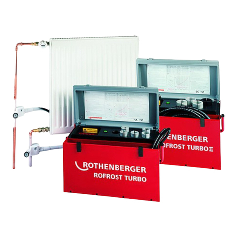
Thefreezeclamps aredesigned for pipes withan
external diameter of 2.1/8“ or 60 mm. Special
reduction inserts (fig. 1) are required for freezing
pipes with a smaller diameter. Generously coat
the contact surfaces with heat transfer com-
pound to avoid insulation by-passing and achie-
veoptimum thermal conductivity andconducting
capacity between the freeze clamps (a), reduc-
tion inserts (b/d) and pipes (fig. 2).
NOTE: Heat transfer compound is required for
the best possible results!
Treat the precision-made,accurate-to-size reduc-
tion inserts and freeze clamps with care! Clean
them after use with a dry cloth and replace in the
insets provided to prevent damage.
Rags soiled with heat transfer compound can be
disposed of without problem as normal waste.
Important:
The freeze clamps and pipes must be kept out
of draughts during the freezing process!
5. Taking out of service
After the work has been completed, pull out the
appliance plug from the mains and allow the fre-
eze clamps and hoses to defrost, before you
remove them from the pipe to clean them.
Caution: do not kink or stretch hoses!
6. Directions for use
The ROFROST TURBO II is a plug-in compact
appliance. It operates with a hermetically sea-
led cooling circuit on the compression principle.
Continuousoperation over several hoursor days
presents no problems.
Thesimple clamping system ofthe freezeclamps
ensures a firm attachment to the pipe.
For attachment, press the clamp and the appro-
priateinset against the pipewhich is to befrozen
and secure with the fixing screw. Remove any
superfluous heat transfer compound.
Caution: tighten the fixing screw only by hand!
In addition, it is recommended that the screw be
greased, as this enables the clamps to be deta-
ched more easily after the freezing process.
Working near a wall or in a constrained position
is made possible by the favourable width across
corners. The freeze clamps are connected to a
flexible, diffusion resistant mono-hose system.
As a result, the ROFROST TURBO II is extreme-
lyhandy, and the 2.5mlong hoses also ensurean
ample working area.
Important:
There can be a temperature difference from dis-
play(L) to display(R)during freezing;this, howe-
ver, is normally compensated for in the minus
range.
Inaddition, external factors may alsoplaya role,
e.g.:
- variableinitial temperatures of the respective
pipes to be frozen
- variable pipe diameters
- variablecontacting of the freezeclamptothe
pipe
- adverse effect of draughts
Switch on the appliance only after both freeze
clampsaresecurelyattachedto the pipeswhich
are to be frozen. The central heating system or
thepump must be switchedoffindue time tostop
the water circulation in the pipes.
Themetal parts of thefreezeclampsreacha tem-
peratureofapprox.-30°Cduring the freezing pro-
cess.To prevent frost-bite, the freeze clamps may
only be handled using suitable thermally insula-
ted gloves.
Re-open the circuit only after the temperature
has reached -18°C and the period stated in the
table (approximate values) has elapsed (fig. 4).
Thevalues stated are approximate values, which
were determined at an ambient temperature of
22°C.
7. Maintenance
The ROFROST TURBO II is designed for use on
construction sites and is therefore contained in
a robust sheet steel case. Nevertheless, handle
itcarefully. Thetechnicalcomponents inside the
appliance are sensitive to rough treatment. As a
result, never drop the appliance or allow it to fall
over.
Should,contrary to expectations, atechnical fault
occurin spite of carefulhandling,pleasecontact
the dealer or the manufacturer directly.
The refrigeration cycle may only be opened by
qualified personnel of the ROTHENBERGER
WERKZEUGE AG.
When the ROTHENBERGER heat transfer com-
poundhas been used up,a further supply canbe
ordered quoting order no. 6.2291.
-7-


