PUMATRONIX ITSCAM 400 Series Product manual

This equipment may be included with lens, which are
sensitive to mechanical impacts such as drops and
extreme vibrations.
14/06/2022
Revision 1.0
Auto iris
Connector
Acrylic
Viewer
Rubber
Lid
Microfit 16 ways
Connector
Ethernet
Connector
* Use the Ethernet connector to connect ITSCAM 400 to the local network.
* Use the Microfit connector inputs to connect ITSCAM 400 to power
source and to signal input equipment for physical triggering, such as an
inductive loop or an optical barrier, for example.
* Utilize as saídas do conector Microfit para conectar a ITSCAM 400 a um
iluminador ou a equipamentos que se deseja controlar, como cancelas ou
portões.
This equipment must be powered from a direct current
(DC) source with a voltage between 12 or 24 Vdc. Do not
connect any of the inputs directly to the power grid (AC)!
2. Make the power connections with the Microfit Connector, at terminals 15
and 16, using the supplied bundle and considering the respective colors of
the V+ and GND signals:
1. Use a 12Vdc or 24Vdc power supply.
Microfit 16 ways
Connector
V+
GND
+-
DC Power
Oxidation Hazard: Electrical and signal connections
made to the ITSCAM 400 bundle and data network cable
must be protected in a terminal box or similar structure
to prevent oxidation of the connections and unwanted
infiltration of liquids into the bundle.

6. Connect ITSCAM 400 to an auxiliary device disconnected from the local
network where the equipment will be installed, using an Ethernet cable:
3. Check the connection's working indication via the Ethernet connector's
LEDs if the device is powered.
4. Check the installation if the LEDs are not indicating that the connection
is working.
5. Use cable with RJ-45 connector with T568B standard pinout:
Ethernet
IP
192.168.0.254
User
admin
Password
123
7. Access the ITSCAM 400 interface in a Google Chrome browser (version
85 or higher) with the factory default data:
8. Go to the menu Settings > Network.
9. Modify the default IP address 192.168.0.254 with netmask
255.255.255.0, considering different values than those that cause conflicts
in the existing network:
11. Check the connection and network configurations after restarting the
ITSCAM 400 device.
10. Click Apply to validate the changes and wait for the equipment to
restart automatically:
The maintenance IP of ITSCAM 400 (192.168.254.254) is
used to recover connection in extraordinary situations
when the primary IP is lost. For this reason, when manually
configuring the network (Ethernet) interface of the
equipment, values other than the maintenance IP must be applied.
13. Repeat steps 6 to 12 in case of connection loss or IP address conflict.
14. Log on with the maintenance IP address 192.168.254.254, in case of
any network conflict.
12. Disconnect the ITSCAM 400 from the auxiliary device and connect the
equipment to the definitive facility's network.
Values that cause conflict
IP Address
Netmask
192.168.254.x
255.255.255.0
192.168.x.x
255.255.0.0
192.x.x.x
255.0.0.0
0.0.0.0
MICROFIT CONNECTOR
TERMINAL AND
COLOR
SIGNAL
1 Green + White
RS232_RX1
2 Purple + White
RS232_TX1
3 Black + White
GND (RS232_1)
4 Purple
RS232_TX2
5 White
RS232_RX2
6 Brown + White
GND (RS232_2)
15. Connect the Serial Port 1 signals to terminals 1 to 3 of the Microfit
Connector, considering the respective colors and signals detailed in the
table:
16. Check the signals of terminals 4, 5, and 6 and their colors to connect
the Serial Port 2 interface.
RX1
TX1 GND
Terminals of Microfit
16 ways Connector
Refer to the technical information of the illuminating
device to make the electrical connections correctly.
18. Connect the ITSLUX illuminator to the same power supply used to
power the ITSCAM 400 device, considering the signal colors used in
connection:
Microfit 16 ways
Connector Terminals
ITSLUX
+-
DC Power
17. Make signal connections to terminals 7 to 14 of the Microfit Connector,
which can be used to receive signals from a loop, optical barrier, or
illuminators activation. The respective terminal colors and signals are
detailed in the table:
MICROFIT CONNECTOR
TERMINAL AND COLOR
SINAL
7 Grey
IN2+
8 Black
In2-
9 Red + White
OUT2+
10 Blue + White
OUT2-
11 Green
IN1+
12 Blue
IN1-
13 Orange
OUT1+
14 Yellow
OUT1-
When using an Illuminator together with ITSCAM 400,
check in the product specifications for the minimum and
maximum distance that must be observed in relation to
the position of the object to be illuminated.
14/06/2022
Revision 1.0

22. Reassemble the fixer following the sequence shown in the picture, if it
becomes detached from the ITSCAM 400 housing:
Thread for
1/4" screw
Rail for moving
the fixing point
Ø4mm hole
for guide pin
28mm
14mm
ITSCAM 400 must be used with a Protection Case
specifically designed for outdoor use and with the
function of protecting equipment from the elements.
Fastening points
19. Select an existing pole or gantry that allows you to position the ITSCAM
400 at road side and parallel to the track, in order to capture images of one
lane of the track and with little horizontal inclination, considering the
maximum angle of rotation:
20. Avoid covering parts of the image by objects such as trees or vehicles
from other tracks.
Line parallel to the track
Maximum Angle
Recommended
30°
* D for ITSCAM 400 CS Mount models = variable.
* D for models with motorized lens ITSCAM 411 (S04L3) and ITSCAM
411 (S04L3A)= 4.5 to 45 meters.
Line parallel to the ground
D
Maximum
Minimum
3,5m to 6m
15°
45°
21. Fix ITSCAM 400 on poles or gantries at a minimum height of 3.5 meters
and maximum of 6 meters (in traffic control applications), considering the
distance D from vehicle crossing point.
27. Tilt the device on the stand respecting a minimum vertical angle of 15°
and a maximum vertical angle of 45° between the lens center and a line
parallel to the ground. In these conditions, the distance D varies according to
the models indicated:
When using an Illuminator together with ITSCAM 400,
check in the product specifications for the minimum and
maximum distance that must be observed in relation to
the position of the object to be illuminated.
Installation Location: In cases where it is not possible to
meet the installation specifications, it is recommended to
consult Pumatronix Technical Support.
30. Tilt the stand with the device to the best framing fit, considering the
maximum angle limit of 45° for vertical tilt, as larger angles of vertical
inclination generate significant deformations in images.
31. Consider using Perspective Adjustments in order to correct the plate
angles in image, if the inclination of the equipment with the stand has
reached the 45° limit, as indicated.
24. Perform the PARAMETERIZATION OF NETWORK INTERFACE as shown
in steps 6 to 13.
28. Access the web interface of the device with the data registered in the
PARAMETERIZATION OF THE NETWORK INTERFACE.
25. Disconnect ITSCAM 400 from the auxiliary device and connect to the
definitive facility's network.
29. Set the OCR processing by device, accessing the Settings > OCR menu
in the interface, considering the image parameters given in the Integration
Manual.
23. Connect the ITSCAM 400 device to a power supply (Steps 1 and 2).
26. Position the ITSCAM 400 with little horizontal inclination so that the
vehicle's license plate is aligned with horizontal on the image, following the
steps in POSITIONING OF ITSCAM 400 ON THE ROAD.
14/06/2022
Revision 1.0

Pumatronix guarantees the product against any defect in material or
manufacturing process for a period of 1 year from the date of issue of
the invoice, provided that, at the discretion of its authorized
technicians, a defect is found under normal conditions of use.
The replacement of defective parts and the performance of services
resulting from this Warranty will only be carried out at the Authorized
Technical Assistance of Pumatronix or a third party expressly indicated
by it, where the product must be delivered for repair.
This Warranty will only be valid if the product is accompanied by a
Maintenance Form duly completed and without erasures and
accompanied by an Invoice.
In compliance with the General Law on Data Protection (LGPD) - Law
No. 13,709, of August 14, 2018, this product has programmable
functions for capturing and processing images that may infringe the
LGPD when used, together with other equipment, to capture personal
data.
Pumatronix is not responsible for the finalities, use and treatment of
the images captured, and the control of the information and forms of
operation of the product are the exclusive decision of the user or
purchaser of the product.
1) Use of software/hardware not compatible with the specifications in
the Manual;
2) Connecting the product to the power grid outside the standards
established in the product manual and installations that present
excessive voltage variation;
3) Infiltration of liquids from opening/closing of the product;
4) Damage caused by natural agents (electric discharge, flood, sea
fog, excessive exposure to climate variations, among other factors) or
excessive exposure to heat (beyond the limits established in the
Manual);
5) Use of the product in environments subject to corrosive gases, with
excessive humidity and/or dust;
6) Show signs of tampering with safety seals;
7) Show signs of opening and modification made by the customer in
places of the product not authorized by Pumatronix;
8) Damage caused by accidents/falls/vandalism;
9) Display adulterated and/or removed serial number;
10) Damage resulting from transportation and packaging of the
product by the customer in conditions incompatible with it;
11) Bad use and in disagreement with the Instruction Manual.
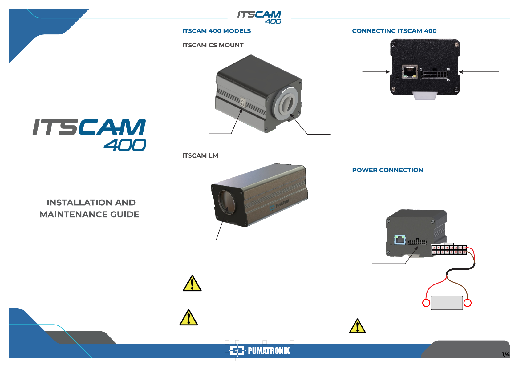
Perform security measures during the upgrade process:
* Keep the ITSCAM 400 device inactivated during the upgrade
process, ensuring that it is not requested by any services or other
equipment on the network where it is installed;
* Keep the ITSCAM 400 device powered on at all times while
performing the upgrade, taking the necessary steps to prevent it
from restarting or being switched of f.
* Request the firmware file by filling out the form available in the Technical
Support menu at Pumatronix website.
* Access in the Product Manual the step-by-step installation of firmware
updates, which can be done through the web interface or the Pumatronix
software.
* For additional information, access the
product manual at www.pumatronix.com.br.
+55 41 3016 – 3173 | suporte@pumatronix.com
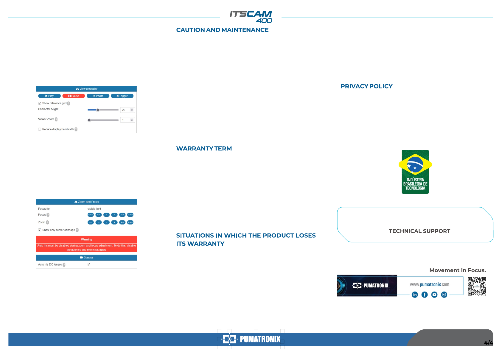
32. Go to the menu Settings > Zoom and Focus on the interface, which can
be done at any time during the configuration process.
34. Use View Control to visualize the live image from the camera via the
Play button. Select the preview image you want to use as a parameter for
zoom configuration and press the Pause button.
36. Use the Viewer Zoom to make it easier the fine adjustment of the plate
framing on the reference grid.
35. Enable the option Show Reference Grid that allows you to use a
Character Height as a basis for the best zoom setting.
33. Disable Auto Iris for a better result (if the ITSCAM 400 model presents
this feature), at page's right side.
37. Use the Show Image Center Only function when you need to reduce
the response time to interface adjustments when accessing via mobile
networks. In this option, the display scale is reduced to 320x240.
38. Click on the adjustment buttons, zooming in and out, also focusing
until the characters become clear in the displayed image.
39. Select the desired zoom and focus position, until the license plate is
readable and under OCR capture conditions (approximate height 20 pixels),
using the character height reference grid.
40. Repeat the steps 26 a 39 until it is possible to obtain an image with the
best framing and sharpness of characters.
14/06/2022
Revision 1.0
Other manuals for ITSCAM 400 Series
1
Other PUMATRONIX Digital Camera manuals