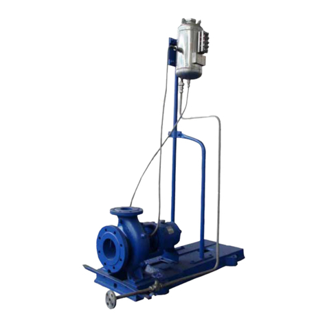
PUMPIRAN PB3 Installation instructions

PB3 centrifugal pumps
Multistage, double suction, horizontally split, centrifugal pump
Doc. No.:
These Operating Instructions Contain Fundamental Information
&Precautionary Notes. Please Read The User Instruction Prior To Installation
Of Unit, Electrical Connection & Commissioning. It is Imperative to Comply
with All Other Operating Instructions Referring to Components of Individual
Units.
Installation
Operation
Maintenance
PB
3
User Instruc
t
ion

PB3 User Instruction
Page 2 of 39
CONTENTS
PAGE
1. INTRODUCTION AND SAFETY 4
1.1 General 4
1.2 CE marking and approvals 4
1.3 Disclaimer 4
1.4 Duty conditions 4
1.5 Safety 5
1.6 Noise level 7
2 TRANSPORT AND STORAGE 8
2.1 Consignment receipt and unpacking 8
2.2 Handling 9
2.3 Lifting 9
2.4 Extended storage 11
2.5 Recycling and end of product life 14
3 INSTALLATION 14
3.1 Location 14
3.2 Foundation 14
3.3 Grouting 15
3.4 Initial alignment 16
3.5 Piping 20
3.6 Electrical connections 23
3.7 Final shaft alignment check 24
3.8 Protection systems 24
4 COMMISSIONING, START-UP, OPERATION AND SHUTDOWN 25
4.1 Precommissioning procedure 25
4.2 Pump lubrication 27
4.2.1 Lubricating oil 27
4.3 Direction of rotation 28
4.4 Guarding 28

PB3 User Instruction
Page 3 of 39
4.5 Priming and auxiliary supplies 29
4.6 Starting the pump 29
4.7 Running or operation 29
4.8 Stopping and shutdown 30
4.9 Hydraulic, mechanical and electrical duty 31
5 MAINTENANCE 32
5.1 Maintenance schedule 33
5.2 Spare parts 33
5.3 Recommended spares and consumable items 34
5.4 Fastener torques 35
6 FAULTS; CAUSES AND REMEDIES 36
7 DRAWINGS AND PARTS LIST 38

PB3 User Instruction
Page 4 of 39
1. INTRODUCTION AND SAFETY
1.1 General
WARNING
These Instructions must always be kept close to product's operating
location or directly
with the product.
PUMPIRAN's products are designed, developed and manufactured with state-of-the-art technologies in modern
facilities. The unit is produced with great care and commitment to continuous quality control, utilizing
sophisticated quality techniques, and safety requirements.
PUMPIRAN is committed to continuous quality improvement and being at service for any further information
about the product in its installation and operation or about its support products, repair and diagnostic services.
WARNING
These instructions are intended to facilitate familiarization with the product and its
permitted use. Operating the product in compliance with these instructions is important to
help ensure reliability in service and avoid risks.
These instructions must be read prior to installing, operating, using and maintaining the
equipment. The equipment must not be put into service until all the conditions relating to
safety, noted in the instructions, have been met.
1.2 CE marking and approvals
Where applicable, the Directives and any additional Approvals, cover important safety aspects relating to
machinery and equipment and the satisfactory provision of technical documents and safety instructions. Where
applicable this document incorporates information relevant to these Directives and Approvals.
1.3 Disclaimer
Information in these User Instructions is believed to be reliable. In spite of all the efforts of PUMPIRAN
to provide sound and all necessary information the content of this manual may appear insufficient and is
not guaranteed by PUMPIRAN as to its completeness or accuracy.
PUMPIRAN manufactures products to exacting International Quality Management System Standards as
certified and audited by external Quality Assurance organizations. The failure to properly select, install or use
authorized PUMPIRAN parts and accessories is considered to be misuse. Damage or failure caused by misuse is
not covered by PUMPIRAN's warranty.
1.4 Duty conditions
This product has been selected to meet the specifications of your purchase order. The acknowledgement of these
conditions has been sent separately to the Purchaser.
WARNING
The product must not be operated beyond the parameters specified for the
application. If there is any doubt as to the suitability of the product for the
application intended, contact PUMPIRAN for advice, quoting the serial number.

PB3 User Instruction
Page 5 of 39
1.5 Safety
1.5.1 Summary of safety markings
These user instructions contain specific safety markings where non-observance of an instruction would cause
hazards. The specific safety markings are:
Symbol Description
This symbol indicates electrical safety instructions where non-compliance will involve
a high risk to personal safety or the loss of life.
This symbol indicates safety instructions where non-compliance would affect personal
safety and could result in loss of life.
This symbol indicates “hazardous substances and toxic fluid” safety instructions where
noncompliance would affect personal safety and could result in loss of life.
This symbol indicates safety instructions where non-compliance will involve some risk
to safe operation and personal safety and would damage the equipment or property.
This symbol indicates explosive atmosphere marking according to ATEX. It is used in
safety instructions where non-compliance in the hazardous area would cause the risk of
an explosion.
This symbol indicates is used in safety instructions to remind not to rub non-metallic
surfaces with a dry cloth; ensure cloth is damp. It is used where non-compliance in the
hazardous area would cause the risk of an explosion.
This sign is not a safety symbol but indicates an important instruction in the assembly
process.
1.5.2 Personnel qualification and training
All personnel involved in the operation, installation, inspection and maintenance of the unit must be qualified to
carry out the work involved. If the personnel in quetion do not already possess the necessary knowledge and
skill, appropriate training and instruction must be provided. If required the operator may commission the
manufacturer / supplier to provide applicable training.
1.5.3 Safety action
This is a summary of conditions and actions to prevent injury to personnel and damage to the environment and
to equipment. (For products used in potentially explosive atmospheres section 1.6.4 also applies.)
Caution
Ensure correct lubrication.
Caution
Prevent excessive external pipe load. Do not use pump as a support for piping. Do not
mount expansion joints, unless authorized by Pumpiran in writing, so that their force,
due to internal pressure, acts on pump flange.

PB3 User Instruction
Page 6 of 39
Caution
Start the pump with outlet valve partly opened (Unless otherwise instructed at a specific
point in the user instructions). This is recommended to minimize the risk of overloading
at full flow and damaging the pump at zero flow.
Pumps
may
be started with the valve
further open only on installations where this situation cannot occur. The
pump
outlet
control valve may need to be adjusted to comply with the duty following the run-up
process. (See section 4, Commissioning start-up, operation and shutdown.)
- Never run the pump dry.
Caution
- Inlet valves to be fully open when pump is running.
- Running the pump at zero flow or below the recommended minimum flow
continuously will cause damage to the pump and seals.
- Low flow rates may cause a reduction in pump/bearing life, overheating of the
pump, instability and cavitation/ vibration.
Caution
Do not run the pump at abnormally high or low flow rates.
Operating at a flow rate higher than normal or at a flow rate with no backpressure on the
pump may overload the motor and cause pump cavitation.
DANGER
Never do maintenance work when the unit is connected to power.
hazardous substances and toxic fluid
When the pump is
handling hazardous
liquids care must be taken to avoid exposure to
the liquid by appropriate sitting of the pump, limiting personnel access and by operator
training. If the liquid is flammable and/or explosive, strict safety procedures must be
applied
HANDLING COMPONENTS
Many precision parts have sharp corners and the wearing of appropriate safety gloves
and equipment is required when handling these components. To lift heavy pieces above
25 kg use an appropriate crane for the mass and in accordance with current local
regulations.
THERMAL
SHOCK
Rapid changes in the temperature of the liquid within the pump will cause thermal
shock, which can result in damage or breakage of components and should be avoided.

PB3 User Instruction
Page 7 of 39
HOT (and cold) PARTS
If hot or freezing components or auxiliary heating supplies can present a danger to
operators and persons entering the immediate area action must be taken to avoid
accidental contact. If complete protection is not possible, the machine access must be
limited to maintenance staff only, with clear visual warnings and indicators to those
entering the immediate are. Note/; bearing housings must not be insulated and drive
motors and bearings may be hot.
If the temperature is greater than 68 °C (154°F) or below -5 °C (20 °F) in a restricted
zone, or exceeds local regulations, action as above shall be taken.
1.5.4 Products used in potentially explosive atmospheres
explosive atmosphere
Measures are required to:
- Avoid excessive temperature
- Prevent the buildup of explosive mixtures
- Prevent the generation of sparks
- Prevent leakages
- Maintain the pump to avoid hazard
The following instru
c
tions for pumps and pump units when installed in potentially explosive atmospheres must
be followed to help ensure explosion protection.
Both electrical and non-electrical equipment must meet the requirements of European Directive 94/9/EC.
1.6 Noise level
Attention must be given to the exposure of personnel to the noise, and local legislation will define when
guidance to personnel on noise limitation is required, and when noise exposure reduction is mandatory.
This is
typically
80
to 85 dBA.
The usual approach is to
control the
exposure time to the noise or to enclose the machine to reduce emitted
sound. Pump noise level is dependent on a number of operational factors, flow rate, pipe work design and
acoustic characteristics of the building, and so the values given are subject to a 3 dBA tolerance and cannot be
guaranteed.
1.6.1 Overall noise level
Tables below show dBA levels for two stage and three or more stage pumps, based on the best efficiency point
BEP at design RPM and required impeller diameter.
For specific gravities less than 1.0, use 1.0 specific gravity. For specific gravities above 1.0, use the actual
specific gravity.
When the required condition flow falls outside the range of 75% to 125% of BEP, a Part Load Correction (PLC)
must be added to the noise levels as follows:

PB3 User Instruction
Page 8 of 39
Percent of BEP at required Impeller Diameter
PLC DB
74 to 62 % or 126 to 136 % +1
61 to 50 % or 137 to 150 % +2
49 to 38 % +3
37 to 25 % +4
2 TRANSPORT AND STORAGE
2.1 Consignment receipt and unpacking
Immediately after receipt of the equipment it must be checked against the delivery/shipping documents for its
completeness and that there has been no damage in transportation.
Any shortage and or damage must be reported immediately to PUMPIRAN and received in writing within one
month of receipt of the equipment. Later claims cannot be accepted.
Check any crates, boxes and wrappings for any accessories or spare parts which may be packed separately with
the equipment or attached to side walls of the box or equipment.
Each product has a unique serial number. Checks that this number corresponds with that advised and always
quote this number in correspondence as well as when ordering spare parts or further accessories.
Brake Horse Power at BEP dBA
3 to 14 Stages
90 to 110 79
110 to 140 80
140 to 180 81
180 to 220 82
220 to 280 83
280 to 360 84
360 to 450 85
450 to 560 86
560 to 720 87
720 to 900 88
900 to 1125 89
1125 to 1400 90
1400 to 1800 91
1800 to 2250 92
2250 to 2800 93
2800 to 3600 94
3600 to 4500 95
4500 to 5700 96
5700 to 7200 97
7200 to 9000 98
9000 to 11000 99
11000 to 14000 100
Brake Horse Power at BEP
dBA
2 stages pump
250 to 350 87
350 to 500 88
500 to 700 89
700 to 940 90
940 to 1100 91
1100 to 1300 92
1300 to 1500 93
Above 1500, Pumpiran 94

PB3 User Instruction
Page 9 of 39
2.1.1 Receipt inspection
NOTE
The following information regarding receiving is only offered as a general guideline
to the customer. PUMPIRAN requires that all receiving be conducted in accordance
with specifications set forth in Chapter 3, Jobsite Receiving and Protection from API
Recommended Practices 686/PIP REIE 686, First Edition.
The pump and its associated equipment were carefully inspected at the factory prior to shipment to
ensure quality compliance. It is suggested that the pump be inspected upon arrival and that any
irregularities or damage be reported to the carrier immediately.
The protective covers on the pump nozzles should be in place and undamaged.
2.1.2 Unpacking
The pump should arrive already mounted on the base plate and it is therefore suggested that the unpacking of
the equipment should proceed per instruction as outlined in this manual.
In general, care is to be taken when removing crating, coverings, and strapping in order not to damage any
auxiliary equipment and/or the paint finish.
2.1.3 Paint/rust preventive
Internal parts of the pump and bearing housings are protected prior to shipment with a rust preventive such as
Dasco guard 2408M. This can be removed with petroleum solvents.
External non-machined surfaces are painted with one of applicable PUMPIRAN coating. Parts ordered
separately are protected with a rust preventive such as Dasco guard 2408M. This can be removed with
petroleum solvents.
2.2 Handling
Boxes, crates, pallets or cartons may be unloaded using forklift vehicles or slings dependent on their size and
construction.
2.3 Lifting
Caution
To avoid distortion, the pump unit should be lifted as shown.
2.3.1 Lifting equipment
NOTE
The following information regarding lifting is only offered as a general guideline.
PUMPIRAN requires that all lifting and rigging be performed in accordance with
specifications set forth in Chapter 2, Lifting and Rigging from API Recommended
Practices 686/PIP REIE 686, First Edition.

PB3 User Instruction
Page 10 of 39
WARNING
EQUIPMENT
CAPACITY
Make sure that any equipment used to lift the pump or any other of its components is
capable of supporting the total weight encountered. Make sure that all parts are properly
rigged before attempting to lift.
2.3.2 To lift unit
Caution
The complete unit with pump, driver and auxiliary equipment all mounted on the
base plate can NOT be lifted as a unit. Driver must be removed from base plate
before lifting. To lift unit sling base plate from all lifting eyes. Failure to do this may
result in permanent deformation of base plate.
Damage to base plate caused by mishandling or improper setting prior to grouting is
not covered by PUMPIRAN’s warranty
2.3.3 To lift driver
Refer to driver manufacturer’s instructions.
2.3.4 To lift pump
Install sling from overhead hoist and under bearing housing mounting brackets (cast portion of casing where
bearing housings attach).
Proper lifting practice for pump
WARNING
LIFTING PRACTICE
Do not lift entire pump from cast lifting lugs on upper half casings. These lugs are
for lifting upper half casing only.

PB3 User Instruction
Page 11 of 39
2.3.5 To lift half casing
To lift upper half casing, rig to overhead hoist from cast lifting lugs provided.
Proper lifting practice for upper case
To lift the pump bottom half casing, slings can be attached to the pump feet, casing bolt holes or padded slings
can be used around the outer casing.
2.3.6 To lift pump rotor
Using slings that will not damage shaft, rig around shaft close to the impellers and to overhead hoist. Carefully
lift rotor from lower half casing.
Proper lifting practice for pump
2.4 Extended storage
NOTE
The following information regarding receiving is only offered as a general
guideline. PUMPIRAN requires that all receiving be conducted in accordance with
specifications set forth in Chapter 3, Jobsite Receiving and Protection from API
recommended Practices 686/PIP REIE 686, First Edition.
During extended periods of storage prior to installation and from the time of installation until commercial
operation, precautions must be taken to protect the pump from deterioration. The various parts of the pump are
protected prior to shipment by applying varying grades of preservative and paint. However, during shipment and
handling, the preservatives are subjected to conditions that can cause their removal. Also, during extended. the

PB3 User Instruction
Page 12 of 39
experience of the person(s) performing the tasks. It should be noted, full responsibility and costs associated with
the storage and inspection of this equipment rests with the customer.
Caution
If pump is equipped with a mechanical seal and is stored or has not been run for 1
year or more, the mechanical seal must be removed before start-up and faces re-
lapped to guard against the possibility of seal leakage. When reinstalling the seal,
new “O” rings and gaskets must be used.
2.4.1 Pump inspection upon arrival
When the pump is received, it should be inspected for damage or other signs of rough handling. Any damage if
found should be reported to the carrier immediately.
Inspect the preservative coating on the various parts. If necessary, renew the preservative in areas where it has
rubbed off or scraped.
Inspect all painted surfaces. If necessary, touch up the areas where paint has been chipped or scraped.
Inspect all covers over pump openings and piping connections. If covers or seals for the covers are damaged or
lose, they are to be removed.
2.4.2 Storage area
When selecting a storage ara, the following should be taken into consideration
a) The deterioration of the equipment will be proportionate to class/type of storage provided.
b)The expense involved in restoring the equipment at time of operation will be proportionate to the class/type of
storage provided,
2.4.3 Storage preferred (dry)
If at all possible, the pump and its components should be stored indoors where they will be protected from the
elements. If it is not possible to store the pump and its components indoors, precautions must be taken to protect
them from the elements.
2.4.3.1 Rotor storage
It is recommended that pump rotor be removed from pump and stored vertically. Rotors may also be stored
horizontally in the pump. Rotors that have to be stored horizontally outside the pump must be supported close to
impeller to eliminate sag that may cause rotor to take a permanent set.
2.4.3.2 Customer inspection
The stored equipment is to be placed on a periodic inspection schedule by the customer.
NOTE
The responsibility for setting up an
inspection and maintenance schedule rests with
the customer and will be dependent upon the class/type of storage provided. It will
be expected that initially inspection would occur weekly, then depending upon the
inspection reports being favorable or unfavorable, inspection would continue
weekly, monthly, or quarterly, as may be determined. Inspection reports must be
kept on file.
Every inspection should consist of a general surface inspection.

PB3 User Instruction
Page 13 of 39
a) Pump supports are firmly in place.
b)
Pump covers over openings are firmly in place.
Pump coverings, plastics or tarps, are firmly in place. Any holes or tears must be repaired to prevent entrance of
dirt or water.
c) Pump covers are periodically removed from openings and interior accessible areas inspected. If surface
rusting has occurred, clean and repaint or re-coat with preservative.
d) If rusting occurs on exterior surfaces, clean and repaint or re-coat with preservative.
e) Loosen casing drain plugs to allow seepage of any accumulated moisture.
f) If the rotor is stored horizontally, rotate pump rotor 1-1/4 revolutions at least once a month to prevent
rotor from taking a permanent set.
Caution
Make sure bearings have adequate lubrication before turning rotor.
The oil inlet blanking plates should be removed and a small amount of oil injected
into the bearings before turning. Refit blanking plates.
g) Periodically remove bearing covers and inspect for accumulation of moisture, rust and foreign material.
As required, clean bearings and bearing housing and re-preserve. Install bearing cover and secure to
assure maximum protection. Bearings removed for storage should be coated with preservative, wrapped
in oil/wax paper, and stored in a warm dry area.
h) Check individually wrapped parts for signs of deterioration. If necessary, renew preservative and
wrapping.
Caution
If storage is over one month, Instrumentation (Controls, Electrical devices,
Temperature switches) should be removed and placed in a climate control
environment if Instrumentation is not powered up.
2.4.4 Storage non-preferred (wet)
It is not recommended that the rotor be subjected to extended periods of submergence or wetting prior to start-
up. However, it is recognized that in some cases, a long period of time may lapse from installation until
commercial operation.
If the pump must be stored after being installed and wetted, the following inspection and maintenance should be
performed.
Isolate the pump with valving - tag (seal) all valves.
Preserve the pump internals.
NOTE
If storage is over one month, Instrumentation (Controls, Electrical devices,
Temperature switches) should be removed and placed in a climate controlled
environment if Instrumentation is not powered up.
Caution
Electric motors (pump driver) should not be stored in damp places without special
protection (refer to motor manufacturer’s instructions).

PB3 User Instruction
Page 14 of 39
2.4.4.1 Painting and preservation
Paints and preservatives used are either PUMPIRAN standard or special as required by the contract
specification. Refer to 2.1.3, Paint/Rust Preventive for the description of paints and preservatives used in this
order or contact the branch office through which the order was placed.
2.5 Recycling and end of product life
At the end of the service life of the product or its parts, the relevant materials and parts should be recycled or
disposed of using an environmentally acceptable method and local regulations. If the product contains
substances which are harmful to the environment, these should be removed and disposed of in accordance with
current regulations. This also includes the liquids and or gases in the "seal system" or other utilities.
hazardous substances and toxic fluid
Make sure that hazardous substances or toxic fluids are disposed of safely and that the
correct personal protective equipment is used. The safety specifications must be in
accordance with the current regulations at all times
3 INSTALLATION
NOTE
The installation/commissioning of this equipment must be conducted in according
with API
Recommended
Practicee 686/PIP REIE 686-First Edition.
3.1 Location
Install the unit close to the source of the liquid to be pumped.
explosive atmosphere
Equipment operated in hazardous locations must comply with the relevant explosion
protection regulations.
When selecting the location, be sure to allow adequate space for operation as well as for maintenance operations
involving dismantling and inspections of parts. Headroom is an important consideration as an overhead lift of
some type is required.
3.2 Foundation
NOTE
The following information regarding foundation is only offered as a general
guideline. PUMPIRAN requires that all foundations be designed and installed in
accordance with specifications set forth in Chapter 4, Foundations from API
Recommended Practices 686/PIP REIE 686, First Edition.

PB3 User Instruction
Page 15 of 39
The design of foundation is not the responsibility of PUMPIRAN. It is therefore recommended that the
customer consult a competent specialist skilled in the field of foundations, to insure proper design/installation of
the foundation.
3.2.1 Installation check list
a) Level Base plate.
b) Preliminary Alignment.
c) Grout Base plate - Check Foundation Bolts
d) Alignment Shaft/Coupling.
e) Piping installed – correct vent, gauge, valve, suction strainer and pipe support locations?
f) Check Coupling Alignment.
g) Coupling guard correctly installed?
3.2.2 Level the baseplate
Before putting the unit on the foundation, thoroughly clean the top of the foundation. Break off any loose pieces
of cement and roughen the top with a chisel to afford a good hold for grout.
NOTE
When lifting base plate with pump, sling base plate from all lifting eyes provided.
Failure to do this may result in permanent deformation of base plate.
NOTE
Pump, driver auxiliary equipment and piping shall be removed from the base plate
before leveling the baseplate.
Locate the base plate in its proper position on the concrete block together with the leveling screws as shown in
the General Arrangement Drawing.
Using a precision level across the machined surfaces of the pump and driver mounting pads, adjust leveling
screws as necessary to ensure that base plate is leveled in all directions.
When the base plate is leveled, snug the foundation bolts, but do not completely tighten.
Using the previous procedure, adjust base plate until pump and driver are within 0.1 mm .
3.3 Grouting
The following ASTM Specifications are furnished as references for test methods used in conjunction with
installation of grouting materials and should be used to obtain proper results:
- ASTM C 78-84, Test Method for Flexural Strength for Concrete
- ASTM C 109-90, Test Method for Compressive Strength of Hydraulic Cement Mortars – Modified
- ASTM C 469-87a, Test Method for Static Modulus of Elasticity and Poisson’s Ratio of Concrete in
Compression
- ASTM C 496-90, Test Method for Splitting Tensile Strength of Cylindrical Concrete Specimens
- ASTM C 531-85, Test Method for Linear Shrinkage and Coefficient of Thermal Expansion of Chemical
Resistant Grouts and Monolithic Surfacing – Modified
- ASTM C 666-90, Test Method for Resistance of Concrete to Rapid Freezing and Thawing
- ASTM C 939-87, Test Method for Flow of Grout for Preplaced Aggregate Concrete (Flow Cone Method)

PB3 User Instruction
Page 16 of 39
3.4 Initial alignment
3.4.1 Shaft/coupling alignment
NOTE
The following information regarding shaft alignment is only offered as a general
guideline. PUMPIRAN requires that all shaft alignment be performed in accordance
with specifications set forth in Chapter 7, Shaft Alignment from API Recommended
Practices 686/PIP REIE 686, First Edition.
Caution
Shaft alignment must be correct for successful operation. Rapid wear, noise,
vibration and actual damage to the equipment may be caused by shaft misalignment.
The shafts must be aligned within the limits given within this section
.
NOTE
Adjustment to correct the alignment in one direction may alter the alignment in
another
direction
. Always check in all directions after making any adjustment.
Coupled equipment must be aligned to minimize unnecessary stresses in shafts, bearings and coupling. Flexible
couplings will not compensate for appreciable misalignment. Foundation settling, thermal expansion or nozzle
loads resulting in base plate/foundation deflection and vibration during operation may require the full coupling
misalignment capability.
3.4.1.1 Alignment methods
The following methods may be used to align equipment train. The methods a) and b) are dial indicator based.
a) Rim and face alignment

PB3 User Instruction
Page 17 of 39
b) Reverse rim indicator alignment
c)
Laser
alignment
.
3.4.2 Dial-indicator-based alignment
3.4.2.1 Check soft foot
Soft foot can affect the alignment readings and should be checked first and eliminated on both pump and driver.
a) Tighten hold down bolts.
b) Set a dial indicator on one foot, loosen the bolt and check if there is an indicator reading. If so place a
shim with the same thickness as the displacement.
c) Check and adjust all feet.
3.4.2.2 Set DBSE
The shaft gap, or distance between shaft ends (DBSE), must be in accordance with the certified General
Arrangement Drawing and must be measured with pump and driver shafts in the center of their axial end float.
Motor with sleeve bearings is to be aligned with rotor at magnetic center.
Move driver to insure proper gap distance.
NOTE
It is recommended that the pump hold down bolting be torqued before taking any
alignment measurements. This makes the pump the fixed machine and driver the
movable machine. In certain cases, however, it may be impractical to move the
driver; therefore; the pump may have to be moved.
3.4.2.3 Determine bracket sag
Bracket sag must be determined and included in the alignment calculation.
a) Install clip with extension pieces and dial indicator(s).
b) Place indicator on top and reset to zero, turn 180° and read indicator and register.
c) Record sag reading obtained at the bottom.
d) Side to side readings need not to be corrected as the sag is equal on both sides.

PB3 User Instruction
Page 18 of 39
3.4.2.4 Determine misalignment and correct vertical plane
Before moving the equipment vertically, it is important that the vertical thermal expansion be taken into
consideration. Refer to General Arrangement Drawing notes and/or driver instructions for recommended cold
vertical setting (if thermal expansion is a factor).
The shims between the motor feet and mounting surface should be clean and dry. This is especially critical for
equipment that has been in service for some time and need to be realigned. Do not use many thin shims, as this
may result in a spongy mounting.
Recommended shim design
3.4.2.5 Determine misalignment and correct horizontal plane
The dial indicators shown below are required to accurately measure the move in the horizontal direction. Move
the driver by bumping with soft hammer/mallet or using the jack-screws (if provided). The amount of horizontal
relocation required is calculated in alignment data sheet.
Dial indicators configuration
NOTE
It is recommended, the completed alignment document be retained as part of your
permanent maintenance file.
3.4.3 Laser alignment
The use of laser alignment greatly simplifies the alignment process. Because of equipment and software
differences, this will only describe laser alignment in general steps.

PB3 User Instruction
Page 19 of 39
3.4.4 Check coupling alignment
The angular and offset coupling alignment must be rechecked.
a) Coupling faces are to be parallel within 0.0254 mm (0.001 in.) TIR.
b) Coupling outside diameters is to be aligned within 0.0762 mm (0.003 in.) TIR.
c) Motor-Driven: “Bump” the motor and check motor rotation.
d) Turbine-Driven: Check turbine rotation. (If wrong, consult turbine manufacturer.)
3.4.5 Assemble coupling
a) Assemble coupling per the manufacturer's instructions.
b) Install coupling guard.
3.4.6 Dowel pump and driver
a) Cold Pumps (temperature below 93 °C (200 °F)) Pump hold down bolts are to be torqued to the proper
value and dowel pins put in two diagonally opposite feet.
b) Hot Pumps
Pumps handling liquids at temperatures of 94 °C (200 °F) and over are designed to permit the casing to expand
with temperature away from coupling end of pump. The units that come under this classification must have the
pump support feet dowelled to the pedestal at the coupling end. This maintains the coupling gap at the desired
amount.
The pump feet at the opposite end are held from moving vertically by the use of a self-locking nut. The
clearance between the base of the nut and the top of the pump foot should be 0.05. A “Gib Block” running
parallel to the length of the pump foot at each of the outboard feet controls the horizontal movement. The "Gib
Blocks" are bolted and doweled to the pedestal. A 0.254 mm (0.010 in.) gap is maintained between the "Gib
Block" and pump foot.
WARNING
The self-locking nuts, which hold the pump from moving in a vertical motion,
are clamped tight to the pump foot at time of shipment. The 0.051 mm (0.002
in.) clearance must be established at time of installation.
Gib block installation sketch for hot pump
c) Pump Driver
Refer to General Arrangement Drawing and/or driver instructions for doweling information.

PB3 User Instruction
Page 20 of 39
3.4.7 Gib block installation for hot applications
Gib blocks are installed to control the direction of the growth while maintaining pump-driver coupling
alignment. They are installed after base plate has been leveled and grouted, suction and discharge piping
connected, and final shaft coupling alignment is completed.
Gib blocks are shipped loose and field installed at the site. The following procedure must be followed for correct
installation of gib blocks.
a) Fully torque the hold-down bolts in the driver end of pumps feet to torque values listed in the instruction
manual.
b) Install the dowel pins in the pump drive end foot by drilling the foot and the base plate for the tapered
dowel provided.
c) Position the gib blocks to obtain a 0.254 mm (0.010 in.) clearance between the gib block and the side of
the non-drive end pump foot as noted on the attached figure. Drill and tap the cap screw holes for the
gib blocks.
d) Tighten the hold-down bolts for the gib blocks.
e) Install the dowel pins in the gib blocks by reaming the block and base plate for the tapered dowel
provided.
f) Tighten the hold-down locknuts on the non-drive end pump feet to establish a 0.051 mm (0.002 in.) gap
between the locknut and the pump foot.
3.4.8 Hot alignment check
A hot check can only be made after the unit has been in operation a sufficient length of time to assume its
NORMAL operating temperature and conditions. If the unit has been correctly cold set, the offset misalignment
will be within 0.076 mm (0.003 in.) TIR and the angular misalignment will be within 0.0254 mm (0.001 in.)
TIR when in operation. If not, make adjustments.
WARNING
Do not attempt any maintenance, inspection, repair or cleaning in the vicinity of
rotating equipment. Such action could result in injury to operating personnel
WARNING
Before attempting any inspection or repair on the pump the driver controls must be
in the "off" position, locked and tagged to prevent restarting equipment and injury
to personnel performing service on the pump.
3.5 Piping
Caution
The following information regarding piping is only offered as a general guideline to
the customer. PUMPIRAN requires that all piping and related systems be
designed/installed in accordance with specifications set forth in Chapter 6, Piping
from API recommended practices 686/PIP REIE 686, First Edition.
The design of piping, and related systems, is not the responsibility of PUMPIRAN. It is therefore recommended
that the customer consult a competent specialist skilled in the field of piping, to insure proper design/installation
of all piping.
Table of contents
Other PUMPIRAN Water Pump manuals
Popular Water Pump manuals by other brands

Grundfos
Grundfos DP AUTOADAPT Series Installation and operating instructions

Lowara
Lowara e-HM series Installation, operation and maintenance

BLACKMER
BLACKMER V Series Installation, operation and maintenance instructions

Crane
Crane Barnes 3SEH-L Installation and operation manual

HALE
HALE SB-156 QUICK REPAIR GUIDE

WAGNER
WAGNER ZIP52 Finishing Translation of the original operating manual