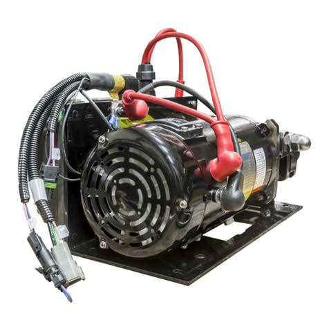
SB–156
QUICK REPAIR GUIDE FOR HALE ESP
ENVIRONMENTALLY SAFE PRIMING PUMP
SB–156 8 Revision A
Replace Vanes And Shaft Seal (ESP Bench Procedure)
This bench procedure is NOT intended to be performed as a stand along procedure. If the ESP re-
quires removal from the apparatus, begin with Step 1. of the main procedure (see Page 3) and per-
form the main and bench procedure(s) in the order instructed. If the ESP is already removed from the
apparatus (or is being repaired in place), begin with Determine Required Repair Kit (Page 5) and per-
form the bench procedure and the remaining portion of the main procedure in the order instructed.
As stated at the bottom of page 5, if the pump body or pump head do NOT exhibit scarring/scoring
(caused by rotor or vane contact) the pump head assembly is serviceable. If the pump head assem-
bly is serviceable, discard the vanes and perform this bench procedure using the 546-1410-03-0
repair kit (Table 1) to replace the shaft seal, install the new vanes, and assemble the ESP.
DO NOT LUBRICATE VANES OR VANE SLOTS. USING LUBRICANT ON
THE VANES OR VANE SLOTS DURING DISASSEMBLY, CLEANING, OR ASSEMBLY
EVENTUALLY CAUSES A GUMMY RESIDUE TO DEVELOP, RENDERING THE ESP INOP-
ERATIVE.
1. Remove all four vanes. See Figure 9.
2. Install four [4] new vanes as follows. See Figure 7 and Figure 9.
Place pump body on its end (pump head mating surface facing up). Placea.
rotor in pump body (tang end facing up).
Position each new vane to align with a slot in rotor.b.
Slide vane into slot until bottomed in slot.c.
Figure 9.
Repeat Step b. and Step c. (above) until all four new vanes are in place.d.
NOTES The vanes must move freely in the rotor slots. Do NOT be concerned if the vanes try
to fall out of the rotor slots due to gravity. Hold the vanes in place until the pump
body is in place to hold them in their slot.
Keep pump body standing on its end to maintain vane positions
while ESP is assembled. See Figure 7.
3. Remove and discard shaft seal. See Figure 2 and Figure 10.
4. Install new seal (Figure 11).
Lightly grease seal and bore of pump head. (Prevents seal damagea.
and aids in assembly.)
Figure 10.
Position new seal with metal cup facing DU bearing (down).b.
Refer to Figure 11.
Drive seal in to pump head as follows.c.
1) Align seal with pump head bore. (Seal must be level with and square to
the bore before/during driving the seal into the bore.)
Figure 11.
NOTE A bearing driver larger than 22 mm will NOT seat the seal all-the-way and a driver
smaller than 20 mm will damage the seal. Use ONLY a 20 or 22 mm driver.
2) Using a 20 to 22 mm bearing driver and a non marring hammer, gently tap seal driver
until seal seats against DU bearing.
